The flying wing design I have been working on for some time now has been slowly evolving as I have learned more about aerodynamics and expanded my skill set with modelling tools of various forms. I have recently completely re-surfaced my design with new aerofoil sections and better, more consistent surface transitions and have been experimentally analysing the results with CFD, courtesy of OpenFOAM. I want to present some of the results here to share.
The lead image is the latest design iteration analysed in OpenFOAM at close to stall angle of attack and the following are a couple of renders of the latest surfacing.
Along with developing methods, I have learned a few things about what makes flying wings tick and how they can be better optimized, at least in the genre that I am pursuing. Some interesting, I hope, insights follow:
Aerofoil selection appears to be the one thing many obsess over when designing a flying wing, but I have found it is only a very small part of the equation and gains made here in two dimensions can be easily lost in the transition to 3D. Many flying wings appear to fly with a large amount of elevon-induced reflex, demonstrating that aerofoil selection alone is inadequate. In a sense, it is equivalent to a large decalage angle to compensate for a low tail volume which is a pretty inefficient way of achieving the design objectives.
I have several iterations of aerofoil in this design, a root foil whose origin is now unclear and a tip foil which started as a symmetrical NACA foil, but wound up with a little camber in the end. Much of the initial development was done in XFLR5 but the CFD proved illuminating in areas not possible with panel code alone.
Washout has proven to be a much more powerful tool to add pitch stability and, in both geometric and aerodynamic senses, has surprised me in how much is actually required to do the job. I have about 7° geometric in this design and in addition have an inverted aerofoil section (a NACA 1308)) for the wingtip to add a relatively large amount of additional aerodynamic washout. Despite this, the undeflected trim speed of this design is of the order of 24-25m/s At this Reynolds number scale, washout has an advantage over reflex that hopefully will become clear shortly. The next image shows the airframe at about 24.5m/s and demonstrates pretty clearly the lift distribution through the downwash trajectory.
One of the big hurdles of flying wings is to maximize the CLmax value which determines the maximum wing loading and landing speeds. Despite the large washout, the stall consistently begins around the tip which is where much of my attention has been focused.
Early on in my investigations I discovered that wing sweep can have deleterious effects on stall performance. In hindsight, I was rediscovering what the Russians already knew from their MiG15 design onwards and attempted to alleviate with those huge wing fences. The effect of wing sweep at stall is a reverse spanwise flow on the upper wing surface. In part this is caused by a changing spanwise pressure gradient as the AoA increases where the inboard high pressure zone is interacting with the lower pressure zones further outboard. The boundary layer flow model below helps visualize this flow regime quite dramatically, although at this Re scale, I predict that it tends to form a laminar separation bubble/vortex running span-wise along the wing surface.
 (MiG-17 showing clearly the wing fences for controlling reverse span-wise flow at high alpha)
As demonstrated in the above illustration, the design optimization of the elevons is an area that is ripe for further DIY exploration. I have found that traditional full-span elevons are counter productive because as the elevon reflex is added, the aerofoil section CLmax is reduced. I have instead experimented with various size and proportion elevons at the wing tips, leaving the inboard wing section unmodified with control surface deflection. This elevon design appears to do the job of increasing the aerodynamic washout of the wing as much as adding reflex, both effects working in parallel to reduce its trim speed accordingly. Unfortunately the foil section modified by the deployment of the elevons tends to be negatively affected giving rise to a large adverse pressure gradient early in the chord causing flow separation bubble formation and loss of lift - the bubble in effect causing a dramatic thickening of the effective aerofoil section with a near total loss of reflex. For this reason, I think washout provides some interesting advantages over reflex at this scale.
To alleviate this separation bubble phenomenon, I have experimented with the use of "spoilerons" - in effect a kind of inverted split-flap design. The top surface of the foil section is deflected upwards leaving the bottom surface unmodified. By opening a gap at the leading edge of the spoiler surface as it is deployed, the negative pressure behind the spoileron tends to improve the pressure gradient along the foil boundary layer helping to delay the inevitable separation somewhat. The spoilerons have also appeared to be extremely effective at quite small sizes relative to conventional flap-type elevons and have led to a minimal impact on drag at low angles of attack.
Spoilerons have not entirely solved the problem of wingtip flow separation so I have added leading edge slots in this latest design iteration. I would not consider them yet optimal, but they tend to add about 4-5% to the CLmax as they stand. They also may have had a non-trivial impact on CD0, but I haven't yet enough data to demonstrate or quantify this.
The results so far predict a best L/D just shy of 12:1 at around 16-17m/s with a span of 975mm and a 1.2kg AUW. There is a small non-linear effect with weight variation due to Reynolds number effects at this scale, some of which can also be seen in the measured drag polar data, where drag at high AoA increases much more sharply than predicted by conventional drag coefficients. This is almost certainly a result of separation bubbles forming - at least theoretically. I don't wish to imply that the CFD data is infallible.
Despite the use of CFD, I haven't yet managed to achieve my theoretical design goal of 10m/s stall speed at the design weight (1.2kg). It currently sits somewhere in the region of 11m/s for a CLmax of 0.65-ish. Note that the reference area is close but still a little unclear at this point due to the "flowing" wing planform so the lift coefficient data probably isn't directly comparable.

I am doing further analysis based on these aerodynamic characteristics to establish propeller selection, range, payload, climb performance, battery size etc, however initial estimates are very encouraging, putting range at or exceeding 100km on 8 x NCR18650B's. With careful airframe design, this allows for at least a 250g payload as well as both video (5.8GHz) and telemetry (915MHz) data links aboard.
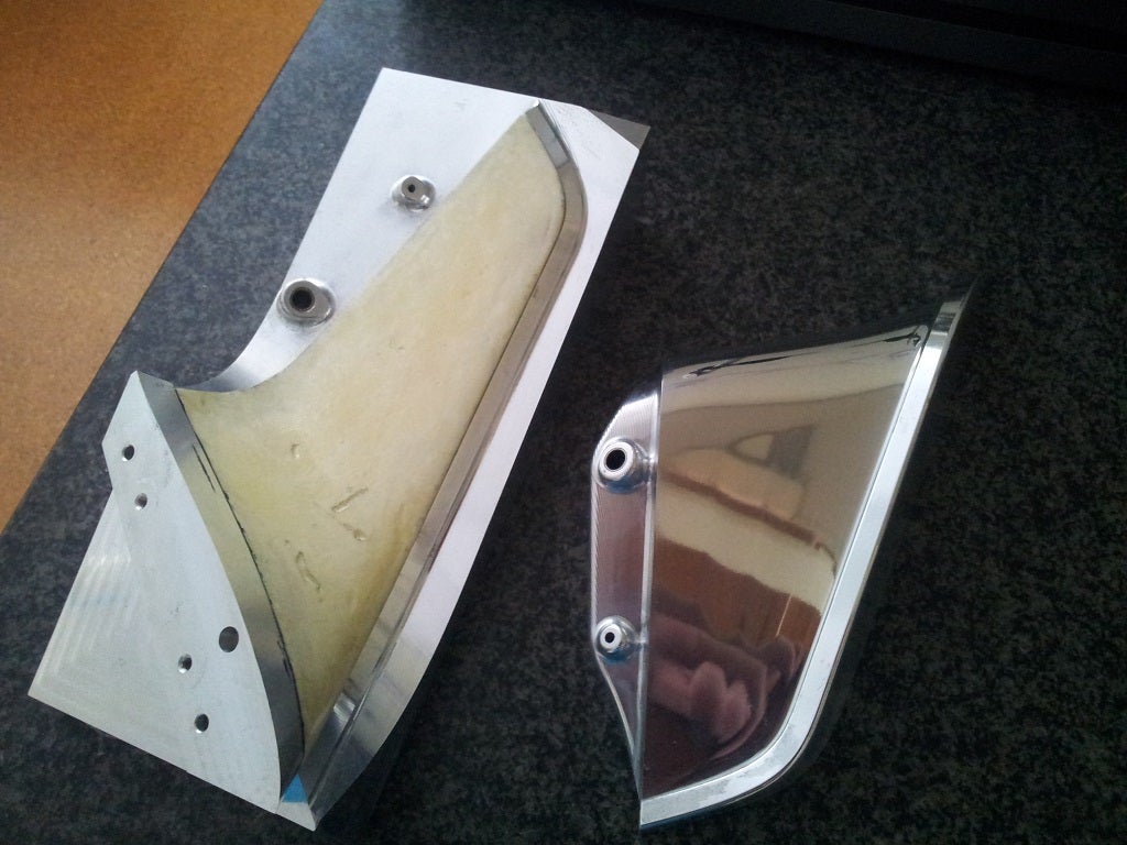
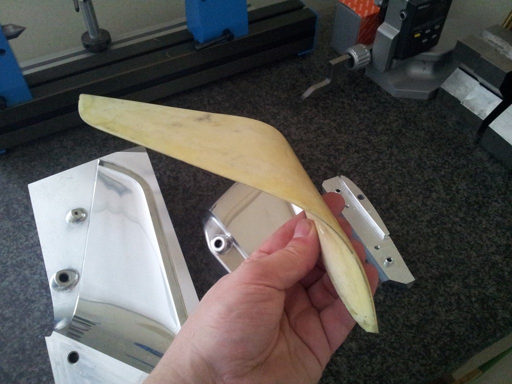
I envisage a fully moulded composite airframe to meet the weight targets, make it robust and to yield a good surface finish for drag minimization. Along side this work, I have been experimenting with some construction techniques on a winglet sample. The results of this experimentation will help drive some of the design and strutural analysis. The potential for high quality surfaces is definitely there but will take some process development and an amount of overly sticky fingers to achieve.
There are a bunch of detail design issues yet to resolve, not least being the manufacturing methods for a robust spoileron at an affordable cost. The non-trivial issue of downward control surface deflection has also to be addressed in mechanical and aerodynamic terms.
Unfortunately as this is all self-funded to date, so progress will continue apace, where the pace will be more tortoise than hare. I hope to publish further info about how I've gone about range analysis, propeller selection as well as some more details about how I've used CFD.
Thanks for reading if you've got this far. I hope it's been interesting
Comments
Hey thanks Doug! Yes, it's a bit of work, but once you get the CFD workflow going, it can be a bit addictive...
This is really impressive. Lots of work. Nice job!
@bgeig, yes, you can use individual .stl files to drive the meshing in many creative ways, as long as the sum of the .stl surfaces forms a closed body. I usually have an individual .stl for patches - inlet, outlet, symmetry plane and the walls of the CFD volume, then the body as an individual .stl or even broken into several .stl's if I want to drive surface refinement to different levels. Yes, it does take a bit of tweaking things to make it behave, but usually once you have your case running, changing it for different cases doesn't normally alter the SHM requirements very much.
re: the mould, it was only about 1/2 hour of 1500 grit and some polish to get it to the state shown in the photo. I can't remember exactly, but about 4-6hrs on the mill for each part prior to that, mostly in the finishing operation.
BTW - I am really impressed with your winglet mold. Is that something you produced in a home shop? Lot of polishing time?
Andrew - thanks. I had not considered .stl files for individual components. That sounds like a great approach. I will have to jump back into the documentation, but I assume openFoam can combine multiple stl files into a single mesh?
I do have one specific question - have you found that a lot of manual tuning of mesh density is needed to get good results with snappyHexMesh (lots of option tweaking)? I assume once you've got the mesh behaving well, changing components isn't a big deal.
I do appreciate your post (and others like it) - this is what makes the site.
@Andrew
Simple build and fly it.
And back after to discuss about deflection, fences, L\D and so on...
Build it.
@Andrew, do the spoilerons only move up?
@Vladimir, of course it's possible as are many other things, but it may or may not be desirable. Your zero control deflection AoA is far away from your best L/D angle that you dramatically modify your aerofoil profile with elevon deflection on your way there. If that's what you want, then sure, but it's no reason to trash my blog post with your self-aggrandizing comments. I was hoping that sharing this would be a positive experience, but frankly you and everyone else who wishes to redesign it for their own ends makes it quite dispiriting. If only you and your ilk would care to share your own designs and ideas in your own blog posts.
Anyway, @bgeig, I have been just using the OpenFOAM tools, blockMesh and snappyHexMesh for my work. It took a while to get it to mesh well and error free but now I have something that works for me, I just copy the case and modify the .stl files that drive the geometry. The more I use it the more familiar I become with the effects of knobs and levers inside the dictionaries, so I encourage you to stick with it. If you have specific questions, please post and I'll try to explain how I understand it.
My work flow is driven by a Solidworks model that has all of the CFD geometry included and allows me to change the AoA and control surface deflection before I export it to individual .stl files for each patch/boundary. I use the export selected object function in SW. I also have a sketch which gives me automatically the dimensions required to locate the reference point for the forces dictionary. Once I have this data, I simply replace the .stl files from before, adjust my dictionary parameters and fire up SHM.
Andrew - Could you share some details on creating the mesh and modifying it in OpenFoam? I have always found that is the hardest problem to overcome when using it. Are you using a commercial grid program or just the OpenFoam tools? Thanks.
-
1
-
2
-
3
-
4
-
5
of 5 Next