Awesome post from Patrick Poirier in the OpenMV forums (OpenMV is my favorite computer vision board, and what I use on our DIY Robocars autonomous racers).
--------
This project is a variation of the original Rand'ys Red Balloon Finder implementation.
Based on this blog : http://diydrones.com/profiles/blogs/red-balloon-finder , I modified the Python scripts making now possible to test on any ArduPilot based Quadcopter on a low budget , relatively easy to implement controller.
Code: Select all
> #This is the configuration script, allowing usage the configuration file > import balloon_config > #We need these modules (installed with dronekit ) to control vehicle> > from pymavlink import mavutil > from dronekit import connect, VehicleMode, LocationGlobal > # connect to vehicle with dronekit > #MAIN > # only process images once home has been initialised > if self.check_home(): > # check if we are controlling the vehicle > self.check_status() > # look for balloon in image > self.analyze_image() > # search or move towards balloon > if self.search_state > 0: > # search for balloon > self.search_for_balloon() > else: > # move towards balloon > self.move_to_balloon()# move towards balloon > # move_to_balloon - velocity controller to drive vehicle to balloon > # calculate change in yaw since we began the search > # get speed towards balloon based on balloon distance > # apply min and max speed limit > # apply acceleration limit > # calculate yaw correction and final yaw movement > # calculate pitch correction and final pitch movemen > # calculate velocity vector we wish to move in > # send velocity vector to flight controller > send_nav_velocity(pitch_final, yaw_final, speed) > # complete - balloon strategy has somehow completed so return control to the autopilot > # stop the vehicle and give up control > # if in GUIDED mode switch back to LOITEROpenMV Script
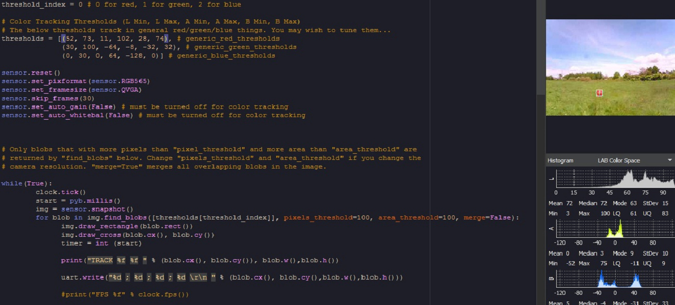
The Red Balloon Finder is a typical colored BLOB Detector/Tracker.
We are adding a serial output to PORT 3 so the x-y location and blob width & height can be transmitted to the RPI Zero.
uart_baudrate = 9600
uart = pyb.UART(3, uart_baudrate, timeout_char = 1000)
uart.write("%d ; %d ; %d ; %d \r\n " % (blob.cx(), blob.cy(),blob.w(),blob.h()))
Some theory
In vision based systems, there are many types of hardware/software configuration tailored for sp[/img]ecific applications: Visual Servoing, Visual Odometry and Visual Simultaneous Localization And Mapping (SLAM). In this project we are using the former type of system: Visual Servoing that is designed to:
• Take off and Landing
• Obstacle Avoidance/Tracking
• Position and Attitude control
• Stabilization over a target
The main idea of Visual Servoing is to regulate the pose {Cξ,T } (position and orientation) of a robotic
platform relative to a target, using a set of visual features {f } extracted from the sensors.
Source: Survey on Computer Vision for UAVs: Current Developments and Trends
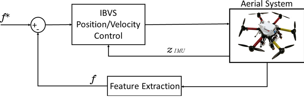
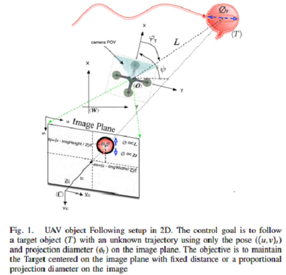
Randy's Target Tracking is an Image Based Visual Servoing (IVBS), where the 2D image features are used for the calculation and control values. We exploit a hybrid method where the size of the object is known -a priori- making the estimation of distance along the Z axis possible. In the example below, were the system is following a moving target at a fixed distance, we can relate the target position to the camera projected plane
Source: 3D Object following based on visual information for Unmanned Aerial Vehicles
In this Tracker, we apply a color and shape (blob) filtering in order to extract a location on the camera plane.
We need to extract position and and estimate the distance by computing the knowned object size with the camera parameters:
lens_mm = 2.8
lens_to_camera_mm = 22
sensor_w_mm = 3.984
sensor_h_mm = 2.952
x_res = 320
y_res = 240
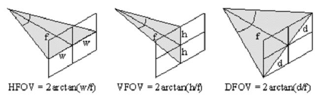
The field of view derives both from the focal length of the lens and the size of the image sensor.
h_fov = 2 * math.atan((sensor_w_mm / 2) / lens_mm)
v_fov = 2 * math.atan((sensor_h_mm / 2) / lens_mm)
In degrees : h_fov = 70.85 , v_fov 55.60
http://chrisjones.id.au/FOV/fovtext.htm
The values coresponding to the object positions and size are transmitted from OpenMV to RPI Zero using serial communication. The python scripting module OpenMV.py reads these values and pass them the Analyze_image() process within Balloon_Strategy_2.py in order to transform position and distance. Here is how we compute the distance:Code: Select all
# get distance self.balloon_distance = get_distance_from_pixels(size, balloon_finder.balloon_radius_expected) ====FROM find_balloon.py==== # define expected balloon radius in meters self.balloon_radius_expected = balloon_config.config.get_float('balloon','radius_m',0.3) # get_distance_from_pixels - returns distance to balloon in meters given number of pixels in image # size_in_pizels : diameter or radius of the object on the image (in pixels) # actual_size : diameter or radius of the object in meters (0.3) def get_distance_from_pixels(size_in_pixels, actual_size): # avoid divide by zero by returning 9999.9 meters for zero sized object if (size_in_pixels == 0): return 9999.9 # convert num_pixels to angular size return actual_size / balloon_video.pixels_to_angle_x(size_in_pixels) ====FROM Balloon_video.py==== # get image resolution self.img_width = balloon_config.config.get_integer('camera','width', 320) # define field of view self.cam_hfov = balloon_config.config.get_float('camera','horizontal-fov', 70.85 ) # pixels_to_angle_x - converts a number of pixels into an angle in radians def pixels_to_angle_x(self, num_pixels): return num_pixels * math.radians(self.cam_hfov) / self.img_width
Building the Tracker System
Depending on the type and size of UAV you are planning to use, the implementation may vary. This build is for a Quadcopter 330 mm size, with a pixracer Flight Controler and a single 5Volts 3 Amps BEC. It is assumed that the UAV is completely functionnal, tested and tuned to be ''rock solid '' in Loiter & Guided mode.
Loading the code, setting parameters & testing
Test&Development environment:
⦁ RPI Zero to a powered USB hub, keyboard, mouse, WIFI, FTDI serial and HDMI monitor
⦁ Window based PC for OpenMV & Mission Planner
⦁ Linux (or VM) based PC for SITL
OpenMV script
Open IDE
Load the Script
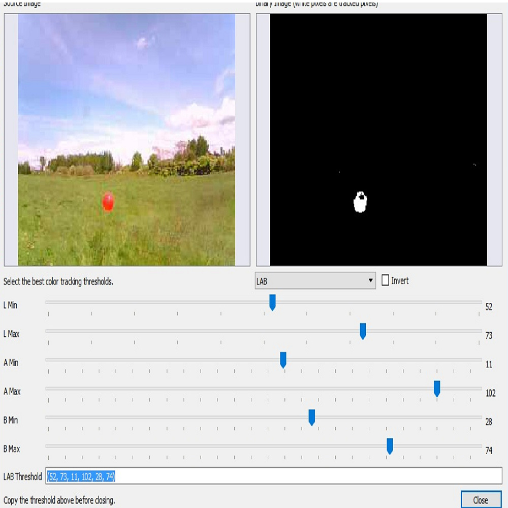
Adjust the color filter using Tools/Machine Vision/ Threshold editor
Make sure you are using LAB color space
Cut the Values & Paste them in the OpenMV script. These values must be inserted in the appropriate thresholds filter code (generic red thresholds for our example):
Run the test and confirm that it is tracking steadily
When satisfied, Tools/Save Open script to OpenMV
Python Script
On your RPI, open a terminal window and clone the program
git clone https://github.com/patrickpoirier51/OpenTracker
_The code is still a WIP , sorry for the mess_
Move to the OpenTracker/script and with an editor (simply open the file with the file manager), adjust the parameters of ballloon_finder.cnf , if required. You can test if the OpenMV to RPI Zero connection is working correctly by launching OpenMV.py using command line : sudo python openmv.py or using IDLE2 editor and running script. Remove the # before print command in order to see the values on console. You can run commands without sudo but it might happen sometimes that you dont have all the priviledge to access codes and devices; its up to each users to test with or without sudo.
Hint:
Ckeck for activity light on FTDI (Show / Hide object) == Knowing the pattern will be helpfull once you are testing live
Once satisfied, comment out the print command, save and you are ready for test.
Testing in SITL
Practice makes good and using SITL may save your day
Leaving the
You can connect the RPI Zero Ftdi Usb to Serial converter to a second FTDI USB to serial on a Linux based computer (dont forget to cross the XMIT to RX(
Launch SITL:
/home/Ardupilot\ArduCopter/$ sim_vehicle.py --console --map --aircraft=balloon --out udp:missopn.planner.pc.adress:14550 --out /dev/ttyUSB0,115200
On the RPI start the Tracker on within a terminal session with sudo python balloon_strategy.py or using IDLE2 editor and running script. Make shure that we connect using Mavlink Serial- USB
connect ( '/dev/ttyUSB0' , baud=115200)
You should see on the RPI console the connection to vehicle, the parameters initialisation sequence and the tracker waiting for command.
On SITL you can initiate this sequence:
⦁ mode loiter
⦁ arm Throttle
⦁ rc 3 1800
⦁ takeoff 30 (wait until it reach this altitude)
⦁ rc 3 1500 (keep altitude in LOITER)
⦁ mode guided
Once in guided, the RPI takes command and you will see the quadcopter start turning, serching for the object.
You can test by ''showing'' the object to the camera for a brief period of time, and you should see the " "Found Balloon at heading:%f Alt:%f Dist:%f" " message appearing. Hide the object and wait until the message "Balloon was near expected heading, finalizing yaw to %f" message appears , starting the final alignment to object , and then you can ''show'' the object and start chasing when you see "Finalized yaw to %f, beginning run"
Now, the simulated vehicle will follow the object on the camera, Looking at the OpenMV IDE you will be able to judge if the simulator react accordingly to the target position on the camera screen. Basically the vehicle will move left-right and up-down (altitude) according to where the object is located in reference to the center of the camera, if its dead center, the simulated quadcopter should go straight with no altitude change.
If you hide the object:Code: Select all
# if we lose sight of a balloon for this many seconds we will consider it lost and give up on the search self.lost_sight_timeout = 3 the tracker will give up : "Lost Balloon, Giving up" and will go through this sequence: # complete - balloon strategy has somehow completed so return control to the autopilot # stop the vehicle and give up control # if in GUIDED mode switch back to LOITEROnce in LOITER you can run another test just by switching back to GUIDED.
Quadcopter Integration
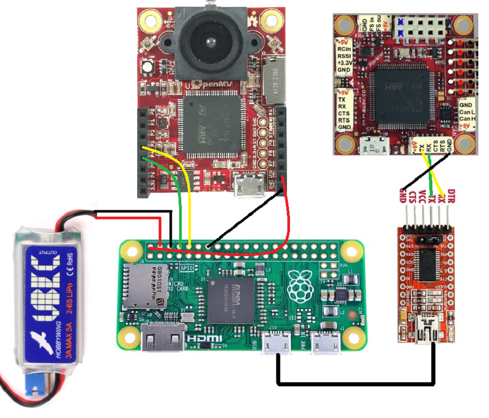
Here is a picture showing the typical installation:
ArduPilot
Adjust the parameter of the Serial (UART - SPEED - MODE) corresponding to the actual speed (115200) and for MavLink protocol.
Configure the flight modes so its easy for you to switch from LOITER to Guided on the Transmitter.
Headless configuration on the RPI Zero
In order to get maximum speed and power, disable the desktop mode (configuration menu or raspi-config)
There are many ways to get the script running automatically, the simplest being launching it within /etc/rc.local
edit file sudo nano /etc/rc.local, and add this:
python /home/pi/OpenTracker/blob/scripts/balloon_strategy_2.py &
"&" is used to make run python in background
Save and reboot
Check for activity light on FTDI (Show / Hide object)
Live Testing
Choose best : Field/Wind/Brightness/Mid Day
Choose the appropriate Object for Target == Red Balloon
Place Target at least 2 Meter from ground
Final adjustment of Target with OpenMV IDE using Threshold utility
Set the best Color Filter Mask and Blob Size
Scan around and Make sure you dont get "False Positive"
Start Quad copter
Check for activity light on FTDI (Show / Hide Target)
Arm
TakeOff Loiter
Switch to Guided (Ready to switch back)
Check Sequence, Analyse Results, Repeat.... Have Fun !!!
Comments
Thanks @Chris for posting this :-)
This project is powered by DroneKit Python, and it does exactly what's advertised:
DroneKit-Python 2.x helps you create powerful apps for UAVs. These apps run on a UAV’s Companion Computer, and augment the autopilot by performing tasks that are both computationally intensive and require a low-latency link (e.g. computer vision).
Hello Rana
Yes you can, the original Balloon Finder is using a C920 connected to an ODROID XU4,
The goal if this project is that you can make a complete autonomous vision system for less than the price of a Logitech C920 camera.
Is it possible to use Logitech C920 HD USB cam ?