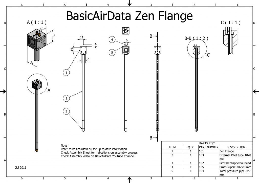
- Figure 1: General Assembly Drawing

Here I share one of the tested DIY designs from BasicAirData
The assembly is fast and revolves around a signle 3D printed part (STL file). An assembly cheat-sheet can be seen in Figure 2.
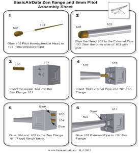
- Figure 2: Assembly Sheet


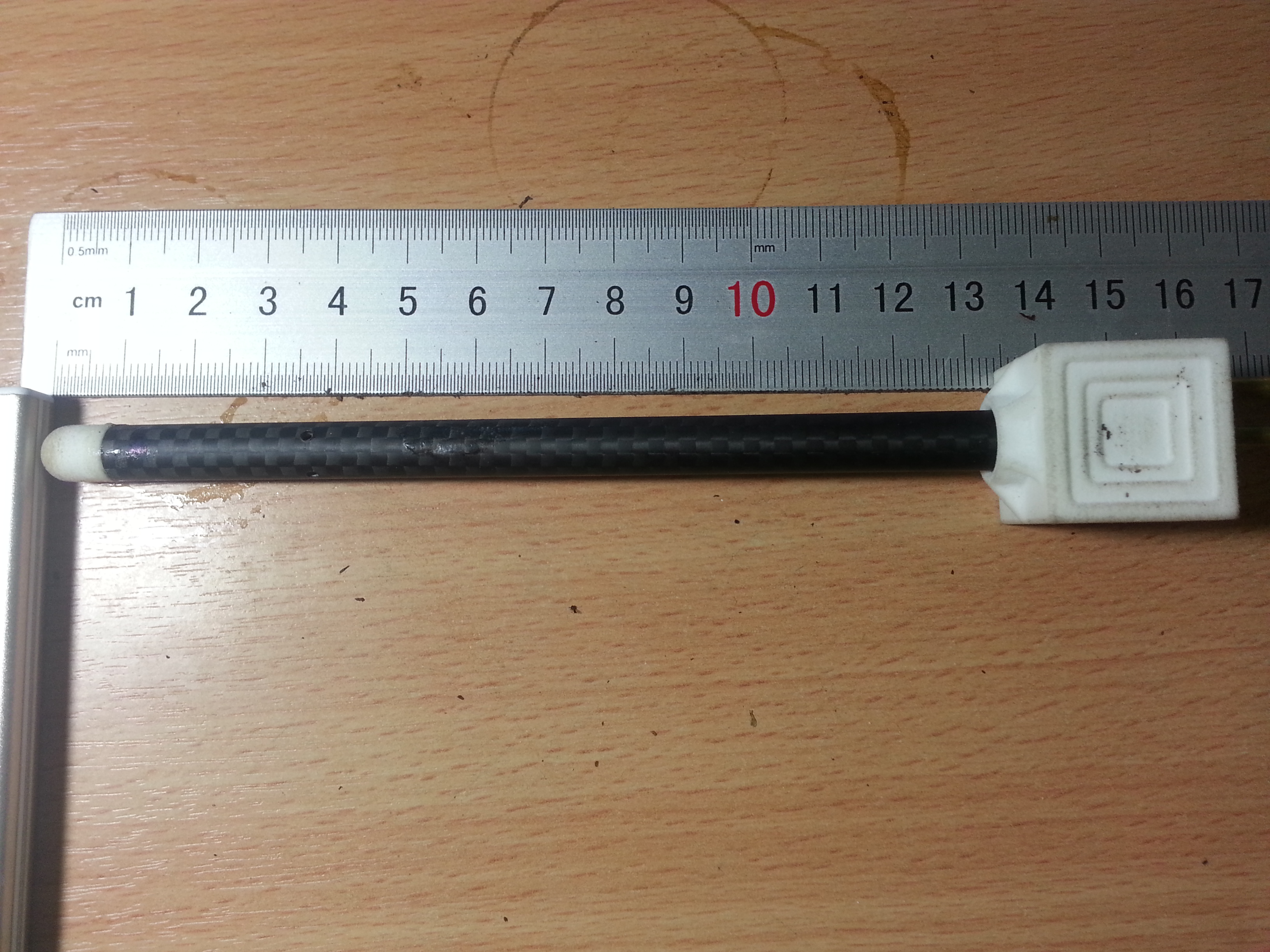
- Figure 3: Printed Zen Flange
The assembly procedure doesn't consist but of trimming three tubes and gluing the whole thing together. Let the overall length of your probe be L(mm), in our example L=200. The overall length is defined as the distance from the tip of the probe to the back of the flange, excluding the nipples.
- The external pipe has an outer diameter of 8mm and an inner diameter of 6mm. A carbon fiber tube is a good choice. Trim it at L-18mm, which is 182mm in our example.
- Drill the static pressure ports on the outer pipe, at a distance of 36mm from the front pipe end. Drill 8 holes of 1mm diameter, 45° apart. This procedure is identical to our previous probe model.
- Cut a nipple of length of 10mm (refer to assembly sheet item 105), for example out of a brass tube, with outer diameter of 3mm and inner diameter of 2mm.
- Cut the total pressure pipe (item 104) at a length of L-7mm (193mm in our case), for example out of a brass tube, with outer diameter of 3mm and inner diameter of 2mm.
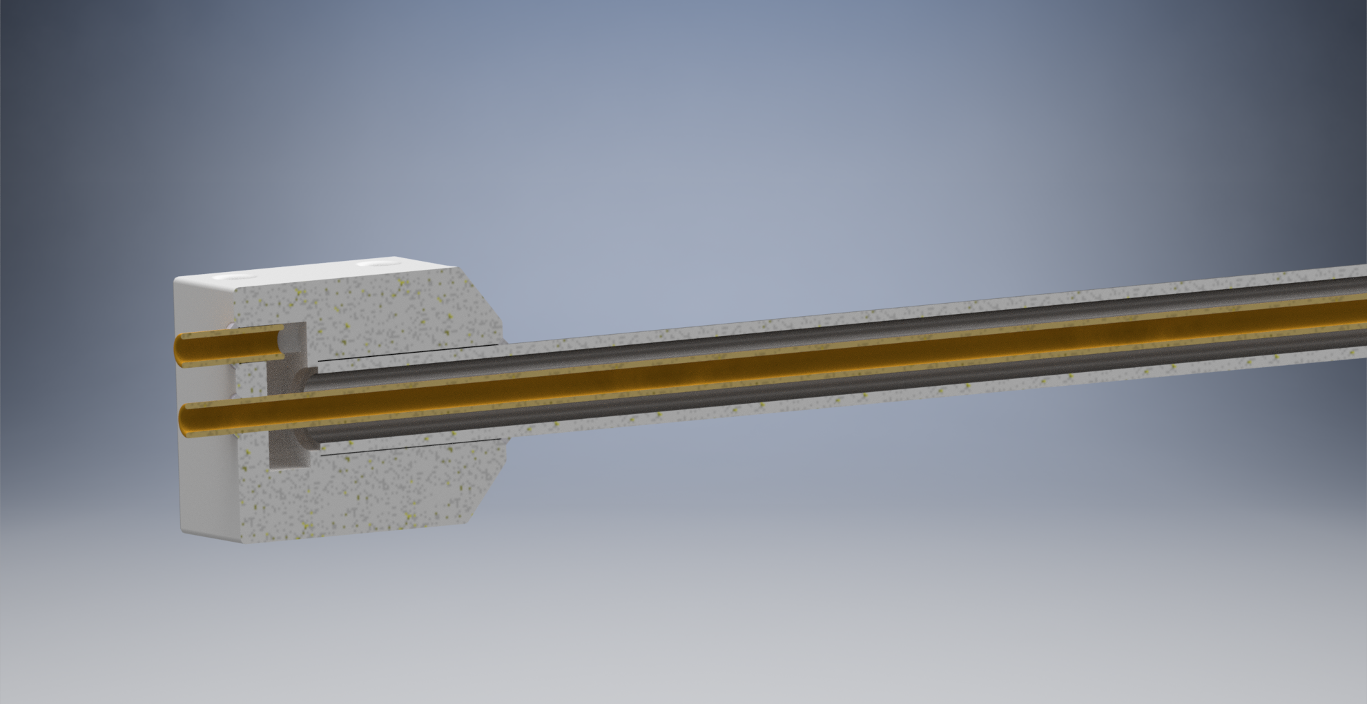
- Figure 4: Rendered Section View
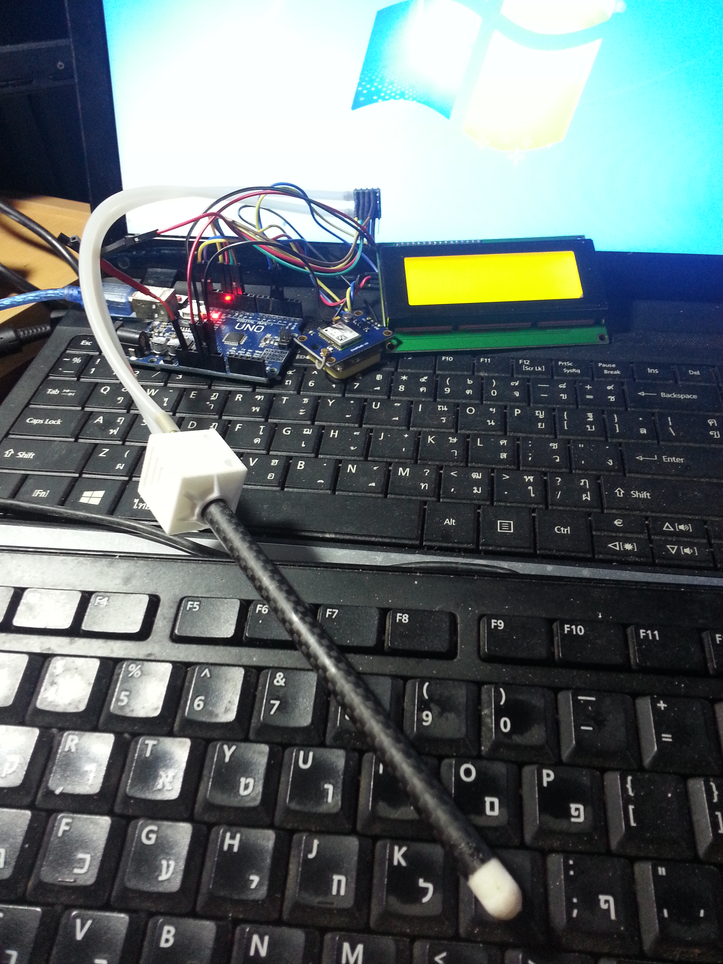
When you have prepared all the parts, make a little assembly check as per Video 1.
After a positive assembly check you can glue the pieces together. The important interface is that between the Pitot head (102) and the total pressure pipe (104). It is critical that this glue seal is airtight. Once you glue the external pipe (103) on the Pitot head you will not be able to repair any leaks.
Once you have glued all the parts together, you should test if the two pneumatic paths are free of obstacles and airtight. If it is available, a Pitot-static tester can be used. If not you can perform a quick test by following this simple procedure:
- Blow into the + nipple. The air should flow unobstructed down to the total pressure port.
- Seal the total pressure port with your finger and blow into the + hole. There should be no air leaks.
- Blow into the - nipple. The air should flow unobstructed down to the static pressure ports.
- Seal the static pressure ports with adhesive tape and blow into the - hole. There should be no leaks.
That's all. You have a brand new DIY pitot!
Comments
Thank you Leonarthall. I never thought about a direct comparison with the 3dr model; anyway, I've tested many commercial probes from different commercial segments. Larger diameter here is more about mechanics and ease of use. A part that some year back I evaluated a prototype for a multi hole probe, to have also an in-flight indication of AOA and AOS, I found unpractical to go below 8/ 9 mm of diameter. From the feedback I receive to the BasicAirData project I can tell there is some buildup around such a kind of DIY probes.
Hi Jose,
These look great!!
I was wondering how these compare to the basic version sold by 3dr. Obviously they are larger and able to project into clean air. Are there other issues we should understand? Does the larger diameter help?
Thanks!!
Many have exposed your needs. In fact we've tested a removable DIY Pitot flange. Follow this link for more info.
Hi Jose. I have read the comprehensive instructions. The only issue is a practical one, that the pitot will be vulnerable when transporting the wing, especially since it's length should ideally exceed the wing chord ahead of the leading edge. Ideally I would like a pitot that can be easily removed for transport. That apart the information on your site is excellent.
Thank you Andy. Yes, you can mount it on the wing. Implementation should be evaluated in function of the wing dimensions and flight envelope. A good installation point can be the wing tip rib, check page 8 of this pdf manual.
Looks great. I am guessing that it is designed to be mounted in the front of a fuselage? Do you have a design that can be mounted on a wing ?