Chris Anderson's Posts (16)
Sort by
From Hackaday:
[Nicholas Rehm] works during the day at the Applied Physics Laboratory at John Hopkins, Maryland, so has considerable experience with a variety of UAV applications. The question arose about how the perseverance mars rover landing worked, which prompted [Nicholas] to hang a rock under his drone, attached via a winch. This proved to be interesting. But what is more interesting for us, is what happens when you try to attach an inverted pendulum to the top of a drone in flight? (video embedded, below)
This is a classic control theory problem, where you need to measure the angle of the pendulum with respect to the base, and close the loop by calculating the necessary acceleration from the pendulum angle. Typically this is demonstrated in one dimension only, but it is only a little more complicated to balance a pendulum with two degrees of freedom.
[Nicholas] first tried to derive the pendulum angle by simply removing the centering springs from an analog joystick, and using it to attach the pendulum rod to the drone body. As is quite obvious, this has a big drawback. The pendulum angle from vertical is now the sum of the joystick angle and the drone angle, which with the associated measurement errors, proved to be an unusable setup. Not to be discouraged, [Nicholas] simply added another IMU board to the bottom of the pendulum, and kept the joystick mechanism as a pivot only. And, as you can see from the video after the break, this indeed worked.
The flight controller is [Nicholas’] own project, dRehmFlight (GitHub), which is an Arduino library intended for the Teensy 4.0, using the ubiquitous MPU6050 6-DOF IMU. [Nicholas] also made an intro video for the controller, which may prove instructive for those wishing to go down this road to build their own VTOL aircraft. The code for pendulum experiment is not available at the time of writing, perhaps it will hit the GitHub in the future?
[note that this was done in a "capture room", which had external cameras that gave the drone precise position information. So it isn't quite the same thing as doing it in the real world.]
The best human drone pilots are very good at doing this and have so far always outperformed autonomous systems in drone racing. Now, a research group at the University of Zurich (UZH) has created an algorithm that can find the quickest trajectory to guide a quadrotor – a drone with four propellers – through a series of waypoints on a circuit. “Our drone beat the fastest lap of two world-class human pilots on an experimental race track”, says Davide Scaramuzza, who heads the Robotics and Perception Group at UZH and the Rescue Robotics Grand Challenge of the NCCR Robotics, which funded the research.
“The novelty of the algorithm is that it is the first to generate time-optimal trajectories that fully consider the drones’ limitations”, says Scaramuzza. Previous works relied on simplifications of either the quadrotor system or the description of the flight path, and thus they were sub-optimal. “The key idea is, rather than assigning sections of the flight path to specific waypoints, that our algorithm just tells the drone to pass through all waypoints, but not how or when to do that”, adds Philipp Foehn, PhD student and first author of the paper in Science Robotics.
External cameras provide position information in real-time
The researchers had the algorithm and two human pilots fly the same quadrotor through a race circuit. They employed external cameras to precisely capture the motion of the drones and – in the case of the autonomous drone – to give real-time information to the algorithm on where the drone was at any moment. To ensure a fair comparison, the human pilots were given the opportunity to train on the circuit before the race. But the algorithm won: all its laps were faster than the human ones, and the performance was more consistent. This is not surprising, because once the algorithm has found the best trajectory it can reproduce it faithfully many times, unlike human pilots.
Before commercial applications, the algorithm will need to become less computationally demanding, as it now takes up to an hour for the computer to calculate the time-optimal trajectory for the drone. Also, at the moment, the drone relies on external cameras to compute where it was at any moment. In future work, the scientists want to use onboard cameras. But the demonstration that an autonomous drone can in principle fly faster than human pilots is promising. “This algorithm can have huge applications in package delivery with drones, inspection, search and rescue, and more”, says Scaramuzza.
From Hackaday:
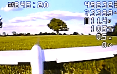
Electric RC aircraft are not known for long flight times, with multirotors usually doing 20-45 minutes, while most fixed wings will struggle to get past two hours. [Matthew Heiskell] blew these numbers out of the water with a 10 hour 45 minute flight with an RC plane on battery power. Condensed video after the break.
 https://hackaday.com/wp-content/uploads/2021/06/2021-06-23-10.png?resize=250,159 250w, https://hackaday.com/wp-content/uploads/2021/06/2021-06-23-10.png?resize=400,254 400w, https://hackaday.com/wp-content/uploads/2021/06/2021-06-23-10.png?resize=800,508 800w" alt="" width="400" height="254" data-attachment-id="483967" data-permalink="https://hackaday.com/2021/06/27/electric-rc-plane-flies-for-almost-11-hours/2021-06-23-10/" data-orig-file="https://hackaday.com/wp-content/uploads/2021/06/2021-06-23-10.png" data-orig-size="1072,681" data-comments-opened="1" data-image-meta="{"aperture":"0","credit":"","camera":"","caption":"","created_timestamp":"0","copyright":"","focal_length":"0","iso":"0","shutter_speed":"0","title":"","orientation":"0"}" data-image-title="2021-06-23 (10)" data-image-description="" data-medium-file="https://hackaday.com/wp-content/uploads/2021/06/2021-06-23-10.png?w=400" data-large-file="https://hackaday.com/wp-content/uploads/2021/06/2021-06-23-10.png?w=800" />
Flight stats right before touchdown. Flight time in minutes on the left, and miles travelled second from the top on the right.
https://hackaday.com/wp-content/uploads/2021/06/2021-06-23-10.png?resize=250,159 250w, https://hackaday.com/wp-content/uploads/2021/06/2021-06-23-10.png?resize=400,254 400w, https://hackaday.com/wp-content/uploads/2021/06/2021-06-23-10.png?resize=800,508 800w" alt="" width="400" height="254" data-attachment-id="483967" data-permalink="https://hackaday.com/2021/06/27/electric-rc-plane-flies-for-almost-11-hours/2021-06-23-10/" data-orig-file="https://hackaday.com/wp-content/uploads/2021/06/2021-06-23-10.png" data-orig-size="1072,681" data-comments-opened="1" data-image-meta="{"aperture":"0","credit":"","camera":"","caption":"","created_timestamp":"0","copyright":"","focal_length":"0","iso":"0","shutter_speed":"0","title":"","orientation":"0"}" data-image-title="2021-06-23 (10)" data-image-description="" data-medium-file="https://hackaday.com/wp-content/uploads/2021/06/2021-06-23-10.png?w=400" data-large-file="https://hackaday.com/wp-content/uploads/2021/06/2021-06-23-10.png?w=800" />
Flight stats right before touchdown. Flight time in minutes on the left, and miles travelled second from the top on the right.
The secret? An efficient aircraft, a well tuned autopilot and a massive battery. [Matthew] built a custom 4S 50 Ah li-ion battery pack from LG 21700 cells, with a weight of 2.85 kg (6.3 lbs). The airframe is a Phoenix 2400 motor glider, with a 2.4 m wingspan, powered by a 600 Kv brushless motor turning a 12 x 12 propeller. The 30 A ESC’s low voltage cutoff was disabled to ensure every bit of juice from the battery was available.
To improve efficiency and eliminate the need to maintain manual control for the marathon flight, a GPS and Matek 405 Wing flight controller running ArduPilot was added. ArduPilot is far from plug and play, so [Matthew] would have had to spend a lot of timing tuning and testing parameters for maximum flight efficiency. We are really curious to see if it’s possible to push the flight time even further by improving aerodynamics around the protruding battery, adding a pitot tube sensor to hold the perfect airspeed speed on the lift-drag curve, and possibly making use of thermals with ArduPilot’s new soaring feature.
A few of you are probably thinking, “Solar panels!”, and so did Matthew. He has another set of wings covered in them that he used to do a seven-hour flight. While it should theoretically increase flight time, he found that there were a number of significant disadvantages. Besides the added weight, electrical complexity and weather dependence, the solar cells are difficult to integrate into the wings without reducing aerodynamic efficiency. Taking into account what we’ve already seen of [rcflightest]’s various experiments/struggles with solar planes, we are starting to wonder if it’s really worth the trouble.
Great post from NASA explaining how the Mars helicopter autopilot works:
----
Before each of Ingenuity’s test flights, we upload instructions that describe precisely what the flight should look like. But when it comes time to fly, the helicopter is on its own and relies on a set of flight control algorithms that we developed here on Earth before Ingenuity was even launched to Mars.
To develop those algorithms, we performed detailed modeling and computer simulation in order to understand how a helicopter would behave in a Martian environment. We followed that up with testing in a massive 25-meter-tall, 7.5-meter-diameter vacuum chamber here at JPL where we replicate the Martian atmosphere. But in all of that work, we could only approximate certain aspects of the environment. Now that Ingenuity is actually flying at Mars, we can begin to assess how things stack up against expectations. Here are some key aspects of the flight control system’s performance on Mars.
Takeoff
Unlike many consumer drones, Ingenuity is not controlled by changing the rotor speeds. Instead, we control our Mars Helicopter in the same manner as full-scale terrestrial helicopters: by changing the pitch angle of the blades, which affects the airfoil “angle of attack” and thereby determines how big a “bite” the blades take out of the air. The bigger the bite, the more lift (and drag) is produced. Like a traditional helicopter, we can change the pitch angle in two ways: by using “collective control,” which changes the blade pitch uniformly over the entire rotation of the blade, and by using “cyclic control,” which pitches the blade up on one side of the vehicle and down on the other.
When Ingenuity takes off, the rotor is already spinning at the setpoint speed of 2,537 rpm. We take off with a sudden increase in collective control on both rotors, which causes the vehicle to “boost” off the ground. During this initial takeoff phase, we limit the control system to respond only to angular rates (how quickly the helicopter rotates or tilts). The reason for this is that we don’t want the control system to be fighting against the ground, possibly resulting in undefined behavior.
The initial takeoff phase lasts for only a split second; once the helicopter has climbed a mere 5 centimeters, the system asserts full control over the helicopter’s position, velocity, and attitude. At this point we’re accelerating toward a vertical climb rate of 1 meter per second.
To estimate our movements during flight, we use a set of sensors that include a laser rangefinder (for measuring altitude) and a camera. We don’t use those sensors until we reach 1 meter altitude out of concern that they might be obscured by dust near the ground. Instead, we initially rely only on an inertial measurement unit (IMU) that measures accelerations and angular rates, and we integrate those measurements to estimate our movements. This is a type of “dead reckoning” navigation – comparable to measuring how far you’ve walked by counting your steps. It’s not very accurate in the long run, but because Ingenuity takes only a couple of seconds to reach 1 meter, we can make it work.
 Ingenuity’s rotor power during Flight Two. Credits: NASA/JPL-Caltech. Download image ›
One of the things we were curious about is how “confidently” Ingenuity would boost off the ground and reach that first threshold of 5 cm. Data from the first three flights shows that portion of the climb took about 0.25 seconds, which is very much in line with expectations and indicates that Ingenuity had no issue producing enough thrust on takeoff. During this initial boost, we expected to see a spike in the power required by the rotor system, and that is indeed what we observed. For example, the spike in Flight Two was about 310 watts (W) – well below the maximum capacity of our batteries, which can tolerate spikes as high as 510 W.
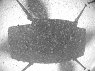 Ingenuity Flight Two: A picture from the navigation camera aboard Ingenuity captured the helicopter on takeoff during Flight Two, showing little sign of dust. Credits: NASA/JPL-Caltech. Download image ›
After takeoff, Ingenuity took about 2 seconds to reach the 1-meter altitude where it could start using its full suite of sensors. That being said, while we did see some faint dust in the images taken by the Perseverance rover (parked nearby) on takeoff, there was no indication flying dust or sand obscured the altimeter or camera, so our design appears to have erred on the cautious side in this regard (which is a good thing).
The moment the helicopter’s legs leave the ground, its motion starts to become affected by wind. These winds can cause the vehicle to momentarily roll (side to side) or pitch (forward or backward) on takeoff, until it has time to catch and correct itself. We were prepared for some significant roll/pitch angles on takeoff if winds were high at the ground level, but in Ingenuity’s three takeoffs so far, they have been limited to a couple of degrees only, making for nice, vertical takeoffs.
Hover
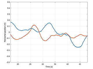 Ingenuity’s horizontal position relative to start during Flight One hover. Credits: NASA/JPL-Caltech. Download image ›
During hover phases of flight, we are attempting to maintain a constant altitude, heading, and position. In evaluating how well we are managing to achieve that, we are forced, for the most part, to rely on Ingenuity’s own estimates of what it was doing, as we have limited data establishing “ground truth.” Those estimates are subject to errors in navigation that will be covered in a separate post. But the steadiness of these estimates tells us a lot about how tightly the controller is able to hold the desired values.
The data shows that we hold our altitude extremely well in hover, to within approximately 1 cm. We also hold the heading (which way we point) to within less than 1.5 degrees. For horizontal position, we’ve seen variations up to approximately 25 cm. Such variations are expected as the result of wind gusts.
So, what has the wind been like during our flights? Fortunately for us, the Perseverance rover carries the MEDA weather station. For Flight One, we have measurements from MEDA indicating winds of 4-6 meters per second from the east and southeast during most of the flight, gusting to 8 meters per second. Keep in mind that those measurements are made 1.5 meters above ground level, and the tendency is for winds to increase as you go from ground level up. We also have atmospheric density measurements at the time of Flight One, showing 0.0165 kilograms per cubic meter, or about 1.3% of Earth’s density at sea level. Using this information, we can assess the system’s performance in another important respect – namely, the control effort required to fly.
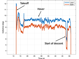 Ingenuity’s collective control during Flight One. Credits: NASA/JPL-Caltech. Download image ›
For the collective control (remember, that is the one that changes rotor blade pitch angle uniformly to affect helicopter’s thrust), we would like to see hover values roughly consistent with prior expectations. During Flight One, we hovered with around 9.2 degrees collective on the lower rotor and 8.2-degree collective on the upper (that’s the angle of the blade’s “chord line” – an imaginary line drawn from the leading edge to the trailing edge of the rotor blade – at ¾ of the rotor radius). Those values are 0.7-0.8 degrees lower than the trim values we anticipated (9.0 degree on the upper rotor and 9.9 degree on the lower rotor). But those trim values were tuned based on tests without wind at a somewhat different density/rotor speed combination, so this difference is not unexpected. Another indication that we are within our aerodynamic comfort zone is the electrical rotor power of around 210 W in hover, which is also right in the vicinity of what was expected. Taken together, the results indicate that we have good margin against “aerodynamic stall,” which is when the blade airfoil’s angle relative to the surrounding airflow is increased beyond the point where it can produce further increases in lift.
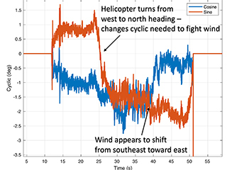 Ingenuity’s lower cyclic control on Flight One. Similar cyclic controls applied on the upper rotor. Credits: NASA/JPL-Caltech. Download image ›
We also evaluate the cyclic control, which is used to create roll and pitch moments on the vehicle. We have seen relatively steady values in hover, generally of magnitude less than 3 degrees, which leaves ample margin against the upper limit of 10 degrees. The cyclic control inputs tell us a fair amount about the wind that the vehicle has to fight against. For example, for Flight One the cyclic control is consistent with winds from the east and southeast, which is in alignment with MEDA observations. The cyclic control effort also increases with altitude, which indicates that winds are getting higher further from the ground.
Landing
Landing is a particularly challenging part of any flight. Ingenuity lands by flying directly toward the ground and detecting when touchdown happens, but a number of events occur in rapid succession leading to touchdown. First, a steady descent rate of 1 meter per second is established. Then, once the vehicle estimates that the legs are within 1 meter of the ground, the algorithms stop using the navigation camera and altimeter for estimation, relying on the IMU in the same way as on takeoff. As with takeoff, this avoids dust obscuration, but it also serves another purpose -- by relying only on the IMU, we expect to have a very smooth and continuous estimate of our vertical velocity, which is important in order to avoid detecting touchdown prematurely.
About half a second after the switch to IMU-only, when the legs are estimated to be within 0.5 meters of the ground, the touchdown detection is armed. Ingenuity will now consider touchdown to have occurred as soon as the descent velocity drops by 25 centimeters per second or more. Once Ingenuity meets the ground, that drop in descent velocity happens rapidly. At that point, the flight control system stops trying to control the motion of the helicopter and commands the collective control to the lowest possible blade pitch in order to produce close to zero thrust. The system then waits 3 seconds to ensure the helicopter has settled on the ground before spinning down the rotors.
People have asked why we contact the ground at the relatively high speed of 1 meter per second. There are multiple reasons for this. First, it reduces the dead-reckoning time that we need to spend without using the camera and altimeter; second, it reduces the time spent in “ground effect,” where the vehicle dynamics are less well-characterized; and third, it makes it easier to detect that we’ve touched down (because the velocity change is clearly sufficient for detection). What makes this strategy possible is the landing gear design which helps prevent the vehicle from bouncing on landing.
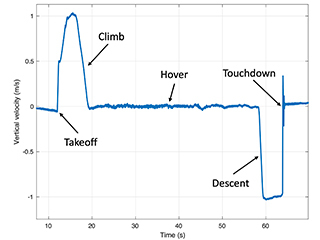 Ingenuity’s estimate of vertical velocity during Flight Two. Credits: NASA/JPL-Caltech. Download image ›
Any touchdown detection algorithm of this kind has to strike a balance between two potential pitfalls: (1) detecting touchdown too early (thereby dropping to the ground from the air) and (2) not detecting touchdown soon enough (which would cause the helicopter to keep trying to fly after coming in contact with the ground). Data from Ingenuity’s flights on Mars show that we were not in danger of either of these scenarios. During descent, Ingenuity has maintained its vertical velocity to within approximately 4 cm per second, and it has detected the necessary 25 cm per second drop within approximately 30 milliseconds of touchdown.
As we continue with our flights on Mars, we will keep digging deeper into the data to understand the various subtleties that may exist and would be useful in the design of future aerial explorers. But what we can already say is: Ingenuity has met or exceeded our flight performance expectations.
From Applied Aeronautics:
Albatross UAV made its first appearance in 2013 on DIY Drones. The Albatross UAV Project, as it was titled, set out to design a composite UAV that met a long list of precise and ambitious performance metrics. Those were: > 6KG MTOW, plenty of room for sensors and batteries, up to 4 hours of flight time, wide flight envelope, and last but not least, efficiency. Over the span of 13 months, the Albatross began to take shape through meticulous design and testing. To date, our company has Albatross systems flying in over 50 countries and on every continent. Still, it’s important to us to always remember our roots as a company spurred by the passion to create something truly incredible from the ground up.
From Hackaday:
Sometimes bad software is all that is holding good hardware back. [Michael Melchior] wanted to scavenge some motors and propellers for another project, so he bought an inexpensive quadcopter intending to use it for parts. [Michael] was so surprised at the quality of the hardware contained in his $100 drone that he decided to reverse engineer his quadcopter and give the autopilot firmware a serious upgrade.
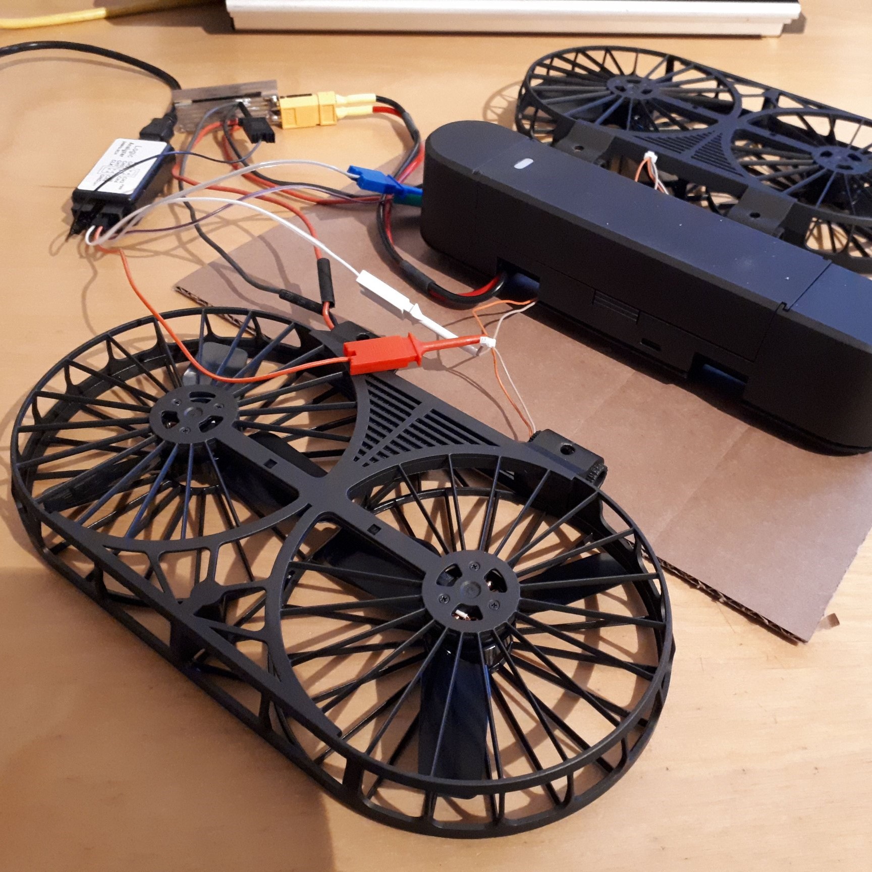 Upon stripping the drone down, [Michael] found that it came with a flight management unit based on the STM32F405RG, an Inertial Measurement Unit, magnetic compass, barometric pressure sensor, GPS, WiFi radio, camera with tilt, optical flow sensor, and ultrasonic distance sensor, plus batteries and charger! The flight management unit also had unpopulated headers for SWD, and—although the manufacturer’s firmware was protected from reading—write protection hadn’t been enabled, so [Michael] was free to flash his own firmware.
We highly recommend you take a look at [Michael]’s 10 part tour de force of reverse engineering which includes a man-in-the-middle attack with a Raspberry Pi to work out its WiFi communication, porting the open-source autopilot PX4 to the new airframe, and deciphering unknown serial protocols. There are even amusing shenanigans like putting batteries in the oven and freezer to help figure out which registers are used as temperature sensors. He achieves liftoff at the end, and we can’t wait to see what else he’s able to make it do in the future.
Of course, [Michael] is no stranger to hacking imported quadcopters, and if you’re interested in PX4 but want something quieter than a quadcopter, take a look at this autopilot-equipped glider.
From Robohub:
For my PhD, I’m studying how global problems such as wildfires and aid delivery in remote areas can benefit from innovative technologies such as UAV (unmanned aerial vehicle) swarms.
Every year, vast areas of forests are destroyed due to wildfires. Wildfires occur more frequently as climate change induces extreme weather conditions. As a result, wildfires are often larger and more intense. Over the past 5 years, countries around the globe witnessed unprecedented effects of wildfires. Greece has seen the deadliest wildfire incident in its modern history, Australia witnessed 18,636,079 hectares being burnt and British Columbia faced wildfire incidents that burnt 1,351,314 hectares.
Rather than jump straight in to the design of swarm algorithms for UAVs in these scenarios, I spent a year speaking with firefighters around the world to ask about their current operations and how UAVs could help. This technique is called mutual shaping where end users cooperate with developers to co-create a system. It’s been interesting to see the challenges they face, their openness to drones and their ideas on the operation of a swarm. Firefighters face numerous challenges in their operations, their work is dangerous and they need to ensure the safety of citizens and themselves. Unfortunately, they often don’t have enough information about the environment they are deploying in. The good news is that UAVs are already used by firefighters to retrieve information during their operations, usually during very short human-piloted flights with small off-the-shelf drones. Having larger drones, with longer autonomy and higher payload, could provide high-value information to firefighters or actively identify and extinguish newly developed fire fronts.
I think one of the reasons we don’t have these swarms in these applications is that 1) we didn’t have the hardware capabilities (N robots with high-payload at a reasonable cost) , 2) we don’t have the algorithms that allow for effective swarm deployments at the scale of a country (necessary to monitor for forest fires), and 3) we can’t easily change our swarm strategies on the go based on what is happening in reality. That’s where digital twins come in. A digital twin is the real-time virtual representation of the world we can use to iterate solutions. The twin can be simplistic in 2D or a more realistic 3D representation, with data from the real-world continuously updating the model.
To develop this framework for digital twins we’re starting a new project with Windracers ltd, Distributed Avionics ltd, and the University of Bristol co-funded by Innovate UK. Windracers ltd. has developed a novel UAV: the ULTRA platform, that can transport 100kg of payload over a 1000km range. Distributed Avionics specialises in high-reliability flight control solutions, and Hauert Lab, which engineers swarm systems across scales – from huge number of tiny nanoparticles for cancer treatment to robots for logistics.
In the future, we aim to use the same concepts to enable aid delivery using UAV swarms. The 2020 Global Report on Food Crises states that more than 135 million people across 53 countries require urgent food, nutrition, and livelihoods assistance. Aerial delivery of such aid could help access remote communities and avoid in-person transmission of highly infectious diseases such as COVID-19.
By the end of this project, we are hoping to demonstrate the deployment of 5 real UAVs that will be able to interact with a simple digital twin. We also want to test live deployment of the control swarm system on the UAVs.
Are you a firefighter, someone involved in aid delivery, do you have other ideas for us. We’d love to hear from you.
I feel like this has been done many times before, including by the Skydio team when they are at MIT, but DARPA was impressed:
From JHU:
Johns Hopkins APL Helps DARPA OFFSET Program Take Flight
In the video above, the APL team’s fixed-wing unmanned aerial vehicle launches in fierce winds from approximately 100 meters away from its target and successfully completes two passes through the crowded urban area while maintaining three meters of space from the target building.
Credit: Johns Hopkins APL
In a second test, the team launched from 250 meters out, flying four times faster than the quadcopters, around a bigger building and under an overpass, autonomously and without crashing.
Credit: Johns Hopkins APL
With each second of the video that ticks away, the suspense builds. Joseph Moore launches a fixed-wing unmanned aerial vehicle (UAV) into the air and it’s buffeted by the wind. Undeterred, the UAV goes about its task to navigate around buildings at high speeds in an urban environment.
The wind picks up at points, and the neon-green fixed-wing UAV steadies itself on those occasions. But ultimately, it navigates the course adeptly, coming within about 10 feet of the buildings and steering around them with relative ease. Most importantly: it doesn’t crash.
“That was a gate for us to get through,” said Moore, the project manager of the Research and Exploratory Development Department team that ran the test at Joint Base Lewis-McChord in Washington state this past August. “We’d never tested anything in an actual physical environment, so proving what we did was huge.”
The test was part of the Defense Advanced Research Projects Agency (DARPA) OFFensive Swarm-Enabled Tactics (OFFSET) program, which envisions swarms of up to 250 collaborative autonomous systems providing insights to ground troops as they operate in dense metropolitan environments. The program is about four years old, Moore said, and it’s unique in structure because the two swarm system integrators — Northrop Grumman and Raytheon — are creating the testbeds and simulation environments for crafting tactics for large-scale autonomous swarms in urban environments.
“OFFSET is developing a variety of swarm-enabling technologies,” said Timothy Chung, the DARPA OFFSET program manager, “from a rich repository of swarm tactics, to virtual environments for swarm simulation, to physical testbeds with real robots where these swarm tactics can be demonstrated in real-world settings.”
This specific test was an effort to answer Moore’s team’s central question for this phase of the project, known as sprints: could fixed-wing UAVs have quadcopter UAV agility and mobility but add greater range, endurance and speed, given that they were fixed-wing in form?
“Imagine you have a futuristic sensor on your aircraft that could, theoretically, map the interior of a building and produce a floor plan,” Moore explained. “You want to put that sensor on a fixed-wing UAV, fly really fast and really close to the building, and come away with a rapid interior scan of the floor plan.
“We’re not there yet, but our goal was to control the vehicle at high speeds in an urban, outdoor environment and do multiple passes around the target building without hitting it.”
UAVs are typically thought of as propeller-armed quadcopters, but previous Independent Research and Development (IRAD) work featuring aerobatic maneuvers with fixed-wing UAVs put APL in an advantageous position to push OFFSET’s fourth sprint forward.
The team took that base work from the IRAD, including its Aerobatic Control and Collaboration for Improved Performance in Tactical Evasion and Reconnaissance (ACCPITER) technology, and spent the first six months of the sprint working with virtual aircraft in a virtual world and the final six using a physical aircraft in a virtually constructed environment.
Using a mesh — a virtual map — of previous DARPA field tests in urban environments, the team flew their fixed-wing UAVs in a virtual world on APL’s campus. They tested, developed the proper algorithms and software, and worked to program an essentially “off-the-shelf” aircraft with bespoke APL-developed electronics package and software.
They did all that at the Lab, but until they trekked to Washington in August, they hadn’t tested it in the physical world. The vehicle’s performance in the virtual world was good. The validation in the physical world performance was exceptional.
In fierce winds, the team launched the craft from approximately 100 meters away, successfully completed two passes through the crowded urban area while maintaining three meters of space from the target building, and then pushed the test to a 250-meter launch, flying four times faster than the quadcopters around a bigger building and under an overpass, autonomously and without crashing.
The program’s fifth sprint is underway, and Moore said this period will focus on adding larger numbers of fixed-wing vehicles operating in urban environments together. The groundwork laid in Sprint 4, especially in validating vehicle performance in the physical world, will be crucial as the team moves forward to address more challenging and complex urban swarm scenarios.
From Hackaday:
Thanks to the availability of cheap, powerful autopilot modules, building small autonomous vehicles is now well within the reach of the average maker. [rctestflight] has long been an enthusiast working in this space, and has been attempting long range autonomous missions on the lakes of Washington for some time now. His latest attempt proved to be a great success. (Video, embedded below.)
The build follows on from earlier attempts to do a 13 km mission with an airboat, itself chosen to avoid problems in early testing with seaweed becoming wrapped around propellers. For this attempt, [Daniel] chose to build a custom boat hull out of fiberglass, and combine both underwater propellers and a fan as well. The aim was to provide plenty of thrust, while also aiming for redundancy. As a bonus, the fan swivels with the boat’s rudder, helping provide greater turn authority.
After much tuning of the ArduPilot control system, the aptly-named SS Banana Slug was ready for its long range mission. Despite some early concerns about low battery voltages due to the cold, the boat completed its long 13 km haul across the lake for a total mission length of over three hours. Later efficiency calculations suggests that the boat’s onboard batteries could potentially handle missions over 100 km before running out.
From the Intel Realsense blog:
Hundreds of thousands of people experience an out-of-hospital cardiac arrest every year. In Europe alone, that number is around 275,000. In the USA, more than 350,000 cardiac arrests occur outside of the hospital each year. While emergency responders do everything they can to respond to these life threatening situations as rapidly as possible, survival rate for out of hospital cardiac arrests can be as low as 10%. When bystanders who witness an attack perform CPR, survival rates increase. Research shows that CPR and defibrillation together when used very quickly after an attack can further, drastically, increase survival and positive outcomes.
Cardiac arrest statistics
In one study by the American Heart Association, researchers looked at almost 50,000 out of hospital cardiac arrests, and specifically studied those arrests which happened in public, were witnessed and where an automated external defibrillator was available. Among their findings:
- Cardiac arrest victims who received a shock from a publicly available AED had far greater chances of survival and being discharged from the hospital than those who did not; 66.5 percent versus 43 percent.
- Cardiac arrest victims who received a shock from a publicly available AED that was administered by a bystander had 2.62 times higher odds of survival to hospital discharge and 2.73 times more favorable outcomes for functioning compared to victims who first received an AED shock after emergency responders arrived.
- Victims who received an AED shock from a bystander (57.1 percent) using a publicly available device instead of having to wait for emergency responders (32.7 percent) had near normal function and better outcomes.
- Without a bystander using AED shock therapy, 70 percent of cardiac arrest patients either died or survived with impaired brain function.
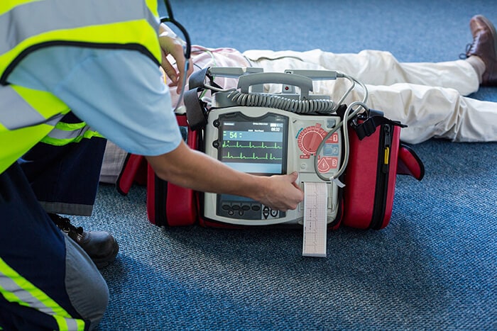 https://www.intelrealsense.com/wp-content/uploads/2020/06/paramedic-300x200.jpg 300w" alt="Paramedic using an external defibrillator" width="700" height="467" aria-describedby="caption-attachment-12322" />
Paramedic using an external defibrillator.
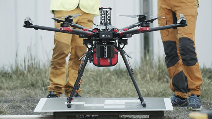
It’s clear from this study that making AED devices available prior to the arrival of emergency responders can make a significant difference in eventual outcomes. Making AED devices available everywhere they could potentially be used is challenging and cost prohibitive. Swedish based Everdrone is looking to solve this problem using an autonomous drone system that allows an emergency medical call center to deliver a defibrillator to the site of a cardiac arrest within a few minutes. By providing the necessary equipment, bystanders will have the ability to initiate life-saving measures while awaiting professional medical care. The operations are carried out by Everdrone and are part of a clinical study in collaboration with Sweden’s national emergency call center, SOS Alarm, and the Centre for Resuscitation Science at Karolinska Institutet.
Autonomous vs. Automated
When talking about drones and robots, it’s essential to understand the difference between automated and autonomous. An automated system performs the same task over and over again. Think about systems like the huge automated robotic arms that build cars. These systems have no awareness of their environment, merely repeating the same movement and task. An autonomous system, on the other hand is able to make decisions based on its physical surroundings. In order for Everdrone’s aerial vehicles to detect obstacles and sense the distance to surrounding objects, they use Intel® RealSense™ D435 depth cameras. The solution is modular and supports up to 7 D435 cameras simultaneously feeding real-time depth data to the drone’s navigation system. The low weight is especially important for a drone which is already carrying relatively heavy AED systems.
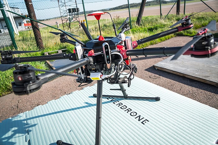
 https://www.intelrealsense.com/wp-content/uploads/2020/06/Everdrone_AED_Images11-300x169.jpg 300w" alt="An Everdrone waiting to take off." width="700" height="394" aria-describedby="caption-attachment-12327" />
An Everdrone waiting to take off.
Safety first
For a system designed to save lives, it’s crucially important that the drone operation itself is safe, especially beyond visual line of sight from the operator. Since these drones could operate and be necessary in a huge variety of environments and conditions, they need an extremely reliable sense and avoid system. Using the Intel RealSense depth cameras combined with Everdrone’s proprietary software, the drones can be kept a safe distance from any obstacles, especially during takeoff and landing and during low-altitude navigation. The system is designed with the highest level of autonomy in mind, and with a level of safety that is on par with what is required for manned aviation. As one of the few companies in the world granted permission for operation in urban environments, Everdrone is clearly delivering safe autonomous operation that can be relied upon.
 https://www.intelrealsense.com/wp-content/uploads/2020/06/everdrone_with_intel_realsense-300x200.jpg 300w" alt="Intel RealSense Depth Camera D435 on the drone." width="700" height="467" aria-describedby="caption-attachment-12332" />
Intel RealSense Depth Camera D435 on the drone.
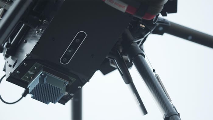 https://www.intelrealsense.com/wp-content/uploads/2020/06/everdrone-with-depth-camera-d435-300x169.jpg 300w" alt="Close up of a D435 on the bottom of the drone – ideal for takeoff and landing." width="700" height="394" aria-describedby="caption-attachment-12337" />
Close up of a D435 on the bottom of the drone – ideal for takeoff and landing.
Other uses
While lifesaving AED delivery is a very important use for these drones, there are also situations where the same drones could be dispatched by emergency services for other uses. For example, an emergency medical call center or emergency response organization could dispatch drones to large incidents as a way to give first responders intelligence about conditions at a disaster site before they arrive. For example, in an earthquake, a drone could help a first responder plan a safe approach or path to their destination, or give important updates on fires or other issues.
From Hackster
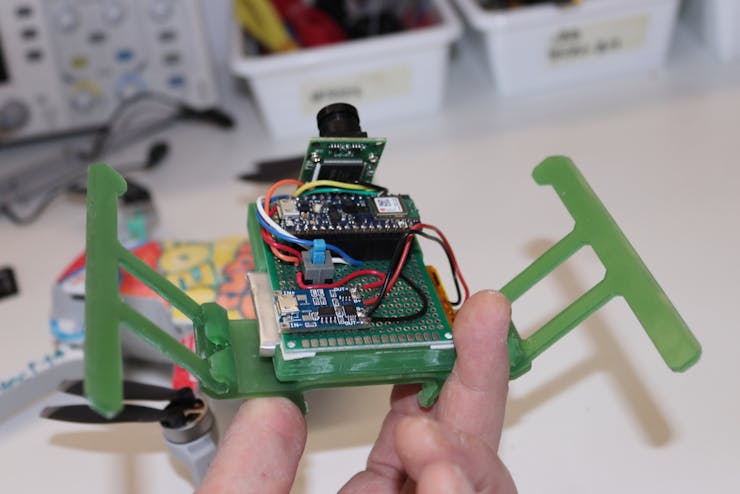
Keeping tabs on plant and crop yield is a difficult job, even with the best farm equipment on hand. Some have gone the high-tech route using SBC-powered cameras to track growth and potential diseases. Still, researcher and developer Enrico Miglino has decided to use a customized drone for plant monitoring and data collection. His Nanodrone is semi-autonomous, and employs sensors and a camera to garner information in real-time along a predefined path using a GPS and a series of waypoints.
Miglino designed his Nanodrone using a DJ Mavic Mini and a 3D-printed undercarriage that houses an Arduino Nano 33 BLE Sense, a forward-facing 2MP SPI Arducam, a GPS board, and a microSD card (for saving information). As mentioned earlier, the Nanodrone uses a series of waypoints for navigation and the camera to identify colors (ripeness) of specific plants, such as fruits and vegetables, which it does leveraging TensorFlow Lite.
Once the Nanodrone has completed its navigation cycle, it then heads to a base station that’s equipped with a PSoC6 Pioneer Kit, where it then delivers the data it has collected via BLE. After a predetermined number of cycles (more than one may be needed), the collected data is then sent over Wi-Fi to a Raspberry Pi, which further processes the readings for more detailed information.
Miglino lists a number of possible applications for his Nanodrone, including plant and tree inspections on small and medium farms, architectural structure variations on time and deformation analysis, and environmental impact changes. For those who would like to recreate his build, Miglino has uploaded a detailed walkthrough of the Nanodrone on his element14 page as the project is still ongoing.
The full schedule of the PX4 virtual developer summit has now been posted. I'm going to be speaking on July 7 on PX4 and the FAA's new drone type certification process.
This is the second annual PX4 developer conference and the first one sold out fast. This one will be virtual of course, which means that it's now much more accessible to people in different countries and time zones. Even better, it's free!
You can see highlights of last year's developer summit here.
From the Shapeways blog, a good interview with PX4-based Quantum Systems:
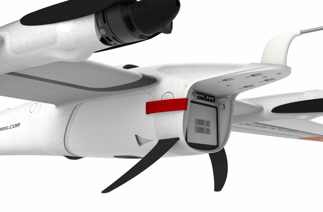
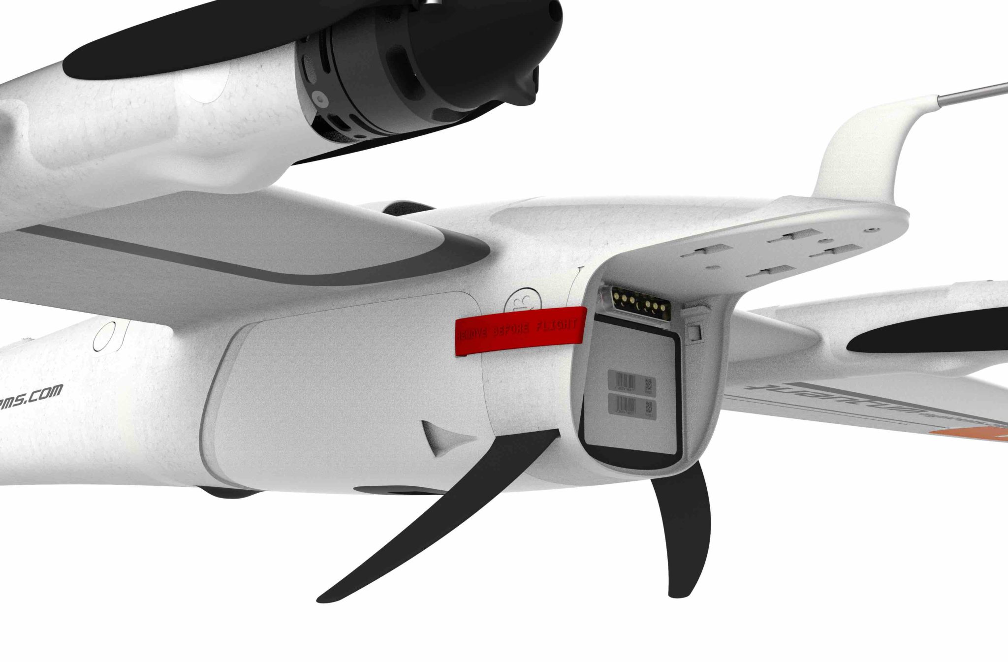
Quantum Systems is a Munich-based company specializing in advanced eVTOL (electric vertical take off and landing) drones. Most recently Quantum Systems tested using their Trinity F90+ to deliver medical samples, opening up new possibilities for applying drone technology to facilitate medical needs.
Founded in 2015, the company has grown quickly by utilizing 3D printing from the beginning of their journey. From rapidly prototyping to printing laser-sintered serial production parts, 3D printing allows for the production of complex but lightweight parts that are free from design constraints, cutting time and mistakes while keeping costs at a minimum.
Quantum Systems has used Shapeways’ printing services to create the ultimate eVTOL aircrafts. We interviewed their CEO, Florian Seibel, to gain more insights on how 3D printing contributes to their drone-making process.
What is your name and role at Quantum Systems?
 Florian Seibel, CEO of Quantum Systems
I am Florian Seibel, and since the founding of Quantum-Systems GmbH in 2015, I’ve held the position of CEO.
The core team of the founders got to know each other as part of their scientific work at the Institute of Flight Systems of the German Armed Forces in Munich. My expertise is the development and the operation of small unmanned aerial vehicles with the focus on design, construction and production methods. With my vision of a licensed, VTOL fixed-wing UAV, I was the initiator of the patent to secure the innovative aspects of the UAV and the driving force behind the founding of the company Quantum-Systems GmbH.
Tell us more about Quantum-Systems
Quantum-Systems GmbH was founded in 2015 in Munich and specializes in the development and production of automatic, electric vertical take-off and landing (eVTOL) fixed-wing drones for a wide variety of use cases. The 50+ employees are working intensively on combining range and electric efficiency with the ability to vertically take off and land without additional equipment.
Our passion is the continuous development of industry-leading VTOL aircrafts. With our ready-to-operate systems we serve a wide range of customers. We help to increase yields in agriculture, fly 3-D reconstruction missions, do tactical mapping for security forces or provide mission-critical video footage in real time to military users. Made in Germany, non ITAR and no back doors in soft or hardware as all of our flight planning and autopilot software is designed in-house.
 https://www.shapeways.com/blog/wp-content/uploads/2020/06/quantum-systems_F90___R6___20200124.PCLock-840x552.jpg 840w, https://www.shapeways.com/blog/wp-content/uploads/2020/06/quantum-systems_F90___R6___20200124.PCLock-420x276.jpg 420w, https://www.shapeways.com/blog/wp-content/uploads/2020/06/quantum-systems_F90___R6___20200124.PCLock-768x504.jpg 768w, https://www.shapeways.com/blog/wp-content/uploads/2020/06/quantum-systems_F90___R6___20200124.PCLock-1536x1009.jpg 1536w, https://www.shapeways.com/blog/wp-content/uploads/2020/06/quantum-systems_F90___R6___20200124.PCLock-2048x1345.jpg 2048w, https://www.shapeways.com/blog/wp-content/uploads/2020/06/quantum-systems_F90___R6___20200124.PCLock-800x525.jpg 800w, https://www.shapeways.com/blog/wp-content/uploads/2020/06/quantum-systems_F90___R6___20200124.PCLock-400x263.jpg 400w, https://www.shapeways.com/blog/wp-content/uploads/2020/06/quantum-systems_F90___R6___20200124.PCLock-300x197.jpg 300w" alt="quantum systems drone with 3d printed parts" width="560" height="368" />
Quantum-System’s Trinity F90+ drone – Main Body. Image source: Quantum Systems
https://www.shapeways.com/blog/wp-content/uploads/2020/06/quantum-systems_F90___R6___20200124.PCLock-840x552.jpg 840w, https://www.shapeways.com/blog/wp-content/uploads/2020/06/quantum-systems_F90___R6___20200124.PCLock-420x276.jpg 420w, https://www.shapeways.com/blog/wp-content/uploads/2020/06/quantum-systems_F90___R6___20200124.PCLock-768x504.jpg 768w, https://www.shapeways.com/blog/wp-content/uploads/2020/06/quantum-systems_F90___R6___20200124.PCLock-1536x1009.jpg 1536w, https://www.shapeways.com/blog/wp-content/uploads/2020/06/quantum-systems_F90___R6___20200124.PCLock-2048x1345.jpg 2048w, https://www.shapeways.com/blog/wp-content/uploads/2020/06/quantum-systems_F90___R6___20200124.PCLock-800x525.jpg 800w, https://www.shapeways.com/blog/wp-content/uploads/2020/06/quantum-systems_F90___R6___20200124.PCLock-400x263.jpg 400w, https://www.shapeways.com/blog/wp-content/uploads/2020/06/quantum-systems_F90___R6___20200124.PCLock-300x197.jpg 300w" alt="quantum systems drone with 3d printed parts" width="560" height="368" />
Quantum-System’s Trinity F90+ drone – Main Body. Image source: Quantum Systems
Why did you choose additive manufacturing and not alternative manufacturing processes?
The complex geometry of 3D-printed parts saves weight by using synergy effects. With synergy effects we mean that with 3D-printed parts we are able to reduce the total number of parts by designing multiple-use parts with integral functionality.
What are the benefits of using additive manufacturing with Shapeways vs using traditional manufacturing?
We used 3D-printing right away, so there is no comparison. Quantum-Systems is a young company. Only because of the fact that we have integrated this manufacturing method into our manufacturing and development process, have we been able to significantly reduce development time. For injection moulded parts we save around 10 weeks by using 3D-printed samples to release the CAD data. The probability that these parts need a second loop of corrections is quite low in this way. For cnc-manufactured parts it is the same, we just often skip the first round of samples with 3D-printed parts which saves us 3-4 weeks. In general I would say 3D-printing saves us 20-50% of time, depending on which parts we design.
What do you value most in additive manufacturing services?
We can have fast iterations in development and save time to mature our prototypes.
Why did you choose Shapeways?
Simple customer interface and good print quality! And on top of that, you are quick!
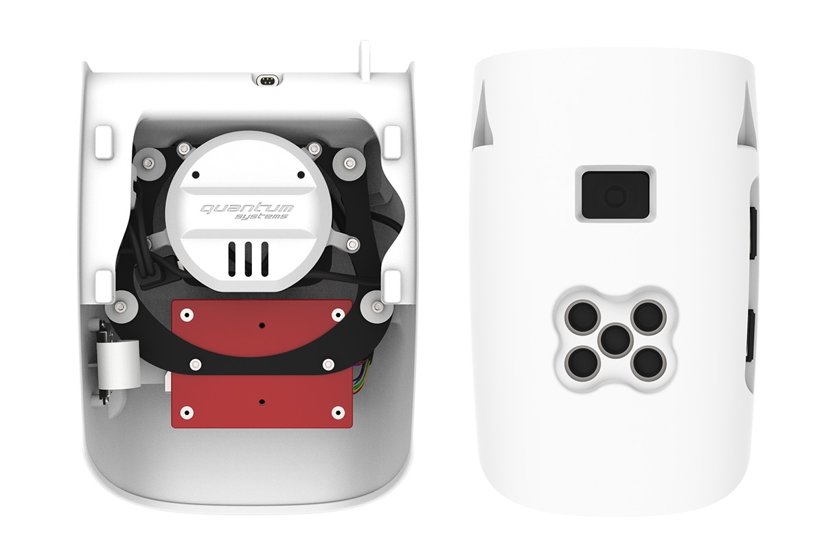 Trinity F90+ Payload Bay with a dual camera mount for RGB and multispectral images. Image source: Quantum Systems
What types of 3D printing do you use Shapeways for?
We have many prototype parts and even some serial production parts laser sintered.
Which materials do you print in and why?
In general, we order Versatile Plastic and HP (Multi Jet Fusion PA12), sometimes colorized. The material properties are perfect for building light and strong drone parts. We prefer HP at the moment, but for some parts, especially big ones, we order Versatile Plastic due to the price.
Any future projects on the horizon?
A lot! And fortunately, all projects require the use of 3D printing. The drones sector still offers a lot of room to pack more features into smaller and more flexible products.
3D printing prototypes and parts has given Quantum Systems the ability to cut substantial time, effort and potential mistakes by streamlining their production process. See how Shapeways can help you prototype and take your designs to the next level.
This season has a theme of using drones for disease response. NXP is offering competitors their PX4-based drone development set (usually $700) for just $300, which is a great deal.
More details here
What will you enable your HoverGames drone to do?
Drones could play a role before, during or after a pandemic – or even prevent a pandemic entirely by controlling outbreaks of disease. How could your code save lives and protect the world?
How about disinfecting surfaces, medicine delivery, dispensing hand sanitizer or masks on-demand, providing social support for quarantined patients or even collecting nasal and throat samples for testing? Or the provision of communication networks in places where internet availability is low? Drones can be flying medical personnel, flying network routers and even flying postal workers, delivering letters or handwritten notes to people in isolation.
TECH YOU'LL USE
You'll use the HoverGames drone development kit. This modular, open development platform uses reliable automotive and industrial-grade components from NXP. You can experiment with additional hardware components from NXP and other providers – you are only bound by your own creativity. And your drone will be PX4-enabled, the largest commercially deployed open-source flight stack worldwide with business-friendly licensing.
The kit contains:
- Flight Management Unit (RDDRONE-FMUK66 FMU) that’s supported by the opensource PX4.org flight stack on top of NuttX RTOS.
- Strong, rigid lightweight carbon fiber quadcopter frame with platform, mounting rails, landing gear, motor controllers, motors and props
- Telemetry radio and remote control (RC) radio
Take your idea and apply for a hardware coupon, now until July 31st
The top 100 applications chosen will receive a coupon.
- If you are new to the HoverGames you pay only $300 (which is a $400 discount) to get the HoverGames drone reference development kit, Remote Control and Telemetry Radio. PLUS, you'll receive our 8MMNavQ experimental custom companion computer using NXP i.MX 8M Mini Vision development board, with a camera module that runs Linux and ROS.
- If you have already joined the HoverGames before and have a drone, pay only $50 ($150 discount) to receive the 8MMNavQ companion computer.
 https://hackster.imgix.net/uploads/attachments/1124445/366577-cs_hovergames-graphic-card-hr_34YApf87EC.jpg?auto=compress%2Cformat&w=1480&h=1110&fit=max 2x" alt="366577-CS_HoverGames-Graphic-Card-HR.jpg" width="100%" />
The top 100 applications chosen will receive a coupon
https://hackster.imgix.net/uploads/attachments/1124445/366577-cs_hovergames-graphic-card-hr_34YApf87EC.jpg?auto=compress%2Cformat&w=1480&h=1110&fit=max 2x" alt="366577-CS_HoverGames-Graphic-Card-HR.jpg" width="100%" />
The top 100 applications chosen will receive a coupon
Pretend we were doing cars, not drones