Nicholas Rehm may be a full-time aerospace engineer, but his success in constructing a DIY self-flying drone that avoids obstacles without standard GPS tech aboard still merits a standing-O. He also gets a deep bow for describing the serious wonkitude involved in a thoroughly entertaining way.
Rehm is no neophyte to homemade drone projects – with or without GPS assistance. Given the education and experience required for his day job, no doubt, his DIY endeavors tend to be a great deal more complex than the typical amateur craft that get (as woebegone Soviet citizens used to put it) “snotted together.” His YouTube page contains over a dozen instructional videos of how he devised and assembled his way-complex UAVs, usually relying on wry understatement or irony to cut the thickness of complex processes he’s detailing.
Quite clearly, Rehm not only brings his work home with him, but indeed creates additional labors of love to infect others with his passion for drones and other aerial craft.
“I am a full-time aerospace engineer, but I like to work on interesting flying projects in my free time: drones, airplanes, VTOL, and everything in between,” he says on his video page. “My goal is to share what I learn along the way and make advanced concepts less scary.”
Which is exactly the miracle he pulls off in this video describing how he made a DIY drone that avoids obstacles without using the standard GPS tech aboard most UAV – and without even needing to be connected to outside communication feeds. Which not only makes his autonomous vehicle immune to collisions or outside jamming devices, but immeasurably cool to boot.
Rehm’s initial idea was to find a viable alternative to habitual autonomous navigation and obstacle avoidance systems. Those require a pre-planned flight path to be entered on a map, waypoint-by-waypoint, that the craft follows in sequence until it reaches the designated destination.
“The drone is actually quite dumb in that it can only fly from one point to the next with no real perception of the world around it, needing to be told what to do for every step of the way,” Rehm explains in the video.
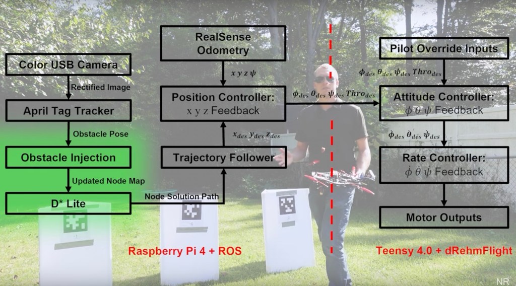
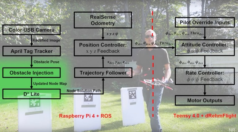
To remedy that, he replaced the foresworn GPS with algorithms powering Google Maps. Those interact with data picked up from the drone’s onboard internal measurement unit, cameras, altitude gauge, position and movement detectors. All of that, orchestrated by a Raspberry Pi 4 using a Robot Operating System, allow the craft to find the way around obstacles it encounters as it advances.
Unlike sequentially progressing as in waypoint-based systems, Rehm’s drone is only told where to go and eventually return to, and is on own from there. As the video demonstrates, when the UAV encounters an obstacle, its programs detect a clear but limited area to either side to take to avoid them. That confined free space detection range is used each time the advancing UAV encounters an obstruction, taking a baby step route around each, but otherwise flying freely until it reaches its destination.
Rather breezily brushing aside the formidable math and engineering needed to pull a feat like his off, Rehm reminds viewers his DIY project is just one of many they can take to greater heights.
“Once you have the building blocks in place for a complex project like this, it’s pretty easy to go back and expand on those individual elements to make the overall system more capable,” Rehm says at the end of the video, his GPS-less drone hovering a few feet away. “For example we could swap out that AprilTag detection algorithm I used for something more robust to maybe detect buildings; or we could expand our motion planning from two dimensions to three.”
Easier for Rehm to say (and believe) than most, though it’s clear he’s sincere in closing out by expressing the motivation for his cutting-edge “snotted together” drone videos.
From Hackaday. You can 3D-print this quad or buy the parts. It uses modified Betaflight firmware:
Quadcopters are great for maneuverability and slow, stable flight, but it comes at the cost of efficiency. [Peter Ryseck]’s Mini QBIT quadrotor biplane brings in some of the efficiency of fixed-wing flight, without all the complexity usually associated with VTOL aircraft.
The Mini QBIT is just a 3″ mini quadcopter with a pair of wings mounted below the motors, turning it into a “tailsitter” VTOL aircraft. The wings and nosecone attach to the 3D printed frame using magnets, which allows them to pop off in a crash. There is no need for control surfaces on the wings since all the required control is done by the motors. The QBIT is based on a research project [Peter] was involved in at the University of Maryland. The 2017 paper states that the test aircraft used 68% less power in forward flight than hovering.
Getting the flight controller to do smooth transitions from hover to forward flight can be quite tricky, but the QBIT does this using a normal quadcopter flight controller running Betaflight. The quadcopter hovers in self-leveling mode (angle mode) and switches to acro mode for forward flight. However, as the drone pitches over for forward flight, the roll axis becomes the yaw axis and the yaw axis becomes the reversed roll axis. To compensate for this, the controller set up to swap these two channels at the flip of a switch. For FPV flying, the QBIT uses two cameras for the two different modes, each with its own on-screen display (OSD). The flight controller is configured to use the same mode switch to change the camera feed and OSD.
[Peter] is selling the parts and STL files for V2 on his website, but you can download the V1 files for free. However, the control setup is really the defining feature of this project, and can be implemented by anyone on their own builds.
I wanted to put this video together to share what I've been working on as it relates to PX4 simulation. I've been really impressed with the capabilities of AirSim and I hope this video makes it a little easier to understand. You can learn more about AirSim here: https://github.com/microsoft/AirSim and my GitBook notes can be found here: https://droneblocks.gitbook.io/airsim... To learn more about DroneBlocks please visit: https://www.droneblocks.io Please feel free to leave a comment below if you have any questions and I hope to share more information in the near future. Thanks for watching.
Researchers at the University of Zurich and the Delft University of Technology have been able to keep a drone flying after a motor fails. The researchers have managed to use onboard cameras to keep the test drones in the air and flying safely.
AD
A team of researchers has come up with a simple yet ingenious way to solve a problem that will usually result in a drone falling to the ground due to a motor failure.
Well, motor failures don’t often happen, but when they do, the drone needs to stay in the air regardless, especially if people are nearby or the drone is being used for a commercial job. Redundancy is important when it comes to drones.
Davide Scaramuzza, head of the Robotics and Perception Group at UZH and of the Rescue Robotics grand challenge at NCCR Robotics, shared:
When one rotor fails, the drone begins to spin on itself like a ballerina. This high-speed rotational motion causes standard controllers to fail unless the drone has access to very accurate position measurements.
Scaramuzza essentially says that the standard controllers in drones cannot cope with the fast and random spinning of a free-falling drone. This led the team to onboard RGB cameras and event cameras, which we’ve gone into in the past for obstacle avoidance.
GPS methods were also explored before the cameras, but the researchers ended up dumping the idea as GPS isn’t available in all situations, especially when it comes to specific drone missions.
The changes between the frames
Now for the way to keep the drone flying. The team equipped a drone with an RGB camera and an event camera. The standard RGB camera detects movements in the whole frame, where the event camera detects changes on the pixel level, allowing for tiny changes to be spotted.
The data from the two cameras are combined using a specially developed algorithm that then tracks the quadcopter’s position relative to its surroundings. This allows the flight controller to take control of the drone as it spins and flies.
Both cameras work great in well-lit environments, but the RGB camera begins to suffer as light decreases. In testing, the researchers were able to keep the drone stable with the event camera all the way down to 10 lux, which is about equivalent to a dimly lit room.
No matter how good we humans have made something, chances are nature did it better millions of years ago. Rather than compete, it’s often better to tap into the natural version – and that’s exactly what scientists have done with the Smellicopter, a drone that uses an antenna from a live moth to sniff out its targets.
We humans don’t tend to rely on it too much, but to moths, the sense of smell is crucial. They use their feathery antennae to scan for the smell of flowers, mates, and other important things, so they’re incredibly sensitive – a single scent molecule can trigger a cascade of cellular responses, very quickly.
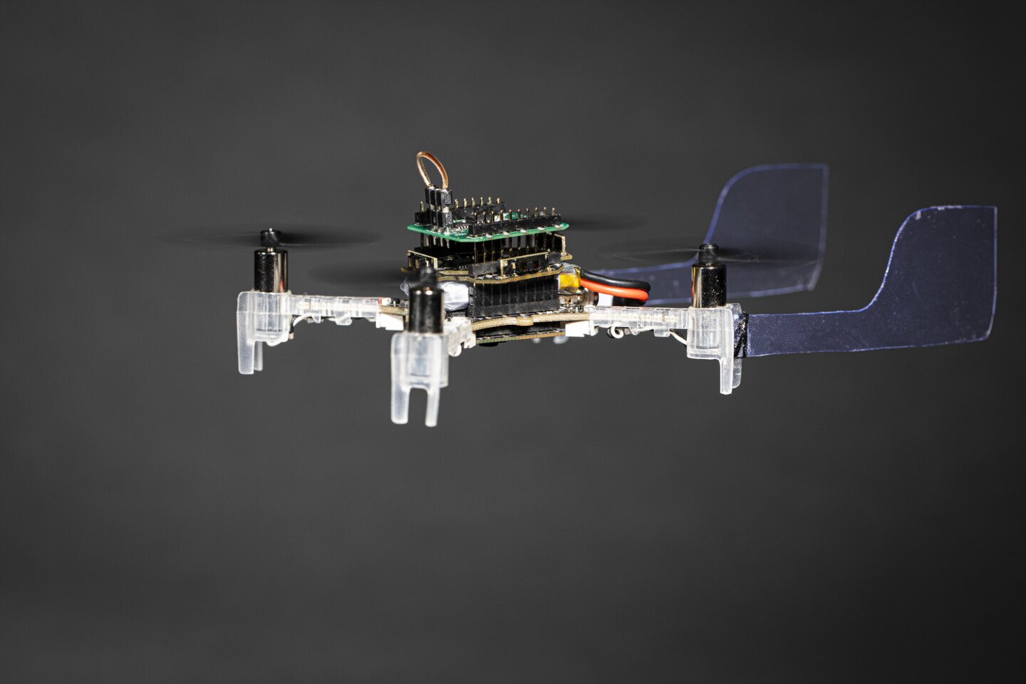
Realizing that, engineers at the University of Washington hooked up an antenna from a live moth to a suite of electronics, and used it to guide a drone towards specific scents. They call the end result the Smellicopter.
“Nature really blows our human-made odor sensors out of the water,” says Melanie Anderson, lead author of the study. “By using an actual moth antenna with Smellicopter, we’re able to get the best of both worlds: the sensitivity of a biological organism on a robotic platform where we can control its motion.”
The antennae are sourced from the tobacco hawk moth, which are anesthetized before removal. Then, small wires are inserted into each end of the hollow antennae, which can measure the average signal from all of its cells. The antenna only stays biologically and chemically active for up to four hours after being removed from a live moth, but the researchers say this could be extended b storing them in the fridge.
The Smellicopter is a drone that uses a live moth antenna as a smell sensor
Mark Stone/University of Washington
To test out the cyborg’s smelling prowess, the team placed it at the end of a wind tunnel, and had it compete with a standard artificial odor sensor. When either a floral scent or the smell of ethanol was wafted down the tunnel, the antenna reacted faster than the other sensor, and was able to cleanse its palette quicker between smells.
For the next experiments, the researchers then mounted the electronics onto a small, common quadcopter platform, which was equipped with two plastic fins to keep it oriented upwind, and four infrared sensors for obstacle detection and avoidance.
Finally, the Smellicopter was driven by an algorithm that mimicked how moths search for smells of interest. The drone starts off by drifting to the left for a set distance, and if it doesn’t detect a strong enough scent, it then moves to the right for a while. When it detects a smell, the drone will then fly towards it. If at any point those infrared sensors pick up an obstacle within 20 cm (8 in), the Smellicopter will change direction.
“So if Smellicopter was casting left and now there’s an obstacle on the left, it’ll switch to casting right,” says Anderson. “And if Smellicopter smells an odor but there’s an obstacle in front of it, it’s going to continue casting left or right until it’s able to surge forward when there’s not an obstacle in its path.”
The team says the device could be useful for seeking out plumes of scent, such as chemical signatures from explosives or the breath of people trapped in rubble. That way, the drones could help in situations where it may be dangerous to send humans to investigate. And it might not be the only insect hybrids doing so – other studies have experimented with using cyborg cockroaches, dragonflies and locusts for similar purposes.
Posted by Chris Anderson on September 27, 2020 at 7:18am
DARPA just conducted its fourth "Swarm tactics" maneuver and once again 3DR Solos are drone of choice. It's a tribute to their open source software and architecture that makes them so flexible and useful, even years after they were made
I'm a big fan of the Marvelmind indoor positioning system, which is inexpensive, accurate (2cm) and quite easy to use. They've now put together a tutorial page on how to use it with drones, both PX4 and Ardupilot:
------
Marvelmind Indoor "GPS" supports PixHawk with ArduPilot and PX4
Build indoor positioning system for quadcopters properly
There are quite many, but rather basic aspects that have to be taken into account to successfully fly indoor:
– Autonomous copter settings manual – basic and practical recommendations for setting up of Indoor “GPS” system for usage with autonomous copters/drones indoor and outdoor
– Placement Manual – practical advises and examples of how to mount the Marvelmind Indoor “GPS” system to achieve the best performance in different applications and configurations
– Check the slides about drones
– Check the slides about Precise Z
– Help: Z-coordinates for copters – long explanation – YouTube explanation how to place the stationary beacons properly to get good Z accuracy. If you can’t use the advises, because your environment doesn’t let you, use the Precise Z configuration with 4+2 stationary beacons
Examples of precise indoor positioning and navigation for drones
Precisely (±2cm) tracking DJI Phantom quadcopter indoor in 3D (XYZ)
– Precise tracking in X,Y,Z (XY view + XZ view + YZ view)
– Raw data and post-processed data from Dashboard’s Player – notice, that today the same is available not in the post-processing, but in the Real-Time Player
– The DJI eco-system is closed, at least, the Phantom and Mavic series. Thus, it is possible to track the Phantom, but not fly autonomously indoor (without deeper hacking)
Precisely (±2cm) tracking DJI Phantom quadcopter outdoor in 3D (XYZ)
– Precise (±2cm) tracking in XYZ (XY view + XZ view + YZ view) – the same as above, but outdoor
– In this demo and in the demo above, the same Precise-Z configuration consisting of 4+2 stationary beacons is used. See more in the Placement Manual
Fully autonomous flight indoor
– Small copter is flying fully autonomously relying on Marvelmind Indoor “GPS”
Indoor tracking small and micro-drones
It is possible to track even micro-drones (less than 100g) with the help of Mini-TX beacons.
The minimum configuration for the drone tracking would be any NIA set with 3D capability. For example, 3 stationary beacons + 1 mobile beacon + 1 modem and Non-Inverse Architecture (NIA) or Multi-Frequency NIA (MF NIA) would be already OK for the drone.
See the Products page for different starter sets options.
However, just 3 stationary beacons would have little resiliency against obstructions. Any occlusion of any stationary beacon – non-line of sight/hearing situation – will lead to no tracking or erroneous tracking. Very much ike in GPS: “no satellites visibility = no GPS coordinates = no tracking”.
Thus, we recommend, at least, N+1 redundancy for stationary beacons. And that is why our starter sets for 3D consist of 4 stationary beacons.
Even better is to have 2N redundancy with fully overlapping 3D submaps. That would be either 3+3 or 4+4 stationary beacons. The system would automatically choose the best submap for tracking. That kind of system is very resilient and with proper placement of the beacons, you can fly even in complex rooms with columns, for example, without issues with tracking.
The key for the great tracking is to provide proper coverage at any flight point, i.e. the mobile beacons on the drone must have 3 or more stationary beacons belonging to the same submap with clear direct line of sight/hearing within 30m.
Proper placement is the key usually and particularly important to drones, because they require 3D; the drones are fast; and the mistakes may be particularly costly. What to pay attention to?
– The single most important requirement for good tracking or autonomous flight – provide clear line of sight/hearing visibility from the mobile beacons on the drone to 3 or more stationary beacons
– Don’t rely on magnetometers indoor. Use the Paired Beacons configuration for Location+Direction
– Place stationary beacons so that angles from the mobile beacons to the stationary beacons would be 30 degree or more. See a longer explanation in the video
– Use the Precise-Z configurations when not possible to achieve proper angles to the stationary beacons otherwise
A team of researchers from Japan and Vietnam have published a paper detailing a novel image processing algorithm capable of reading floor features accurately enough to allow drones to navigate autonomously indoors using a simple low-resolution camera.
There's nothing new about the concept of autonomous drones, but technologies which work well for navigation outdoors — in particular GPS and other global navigation satellite systems (GNSSes) — don't always translate well to indoor use. "We considered different hardware options, including laser rangefinders," explains lead author Chinthaka Premachandra of his team's work. "But rangefinders are too heavy, and infrared and ultrasonic sensors suffer from low precision. So that led us to using a camera as the robot's visual sensor. If you think of the camera in your cell phone, that gives you an idea of just how small and light they can be."
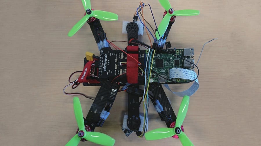
The prototype developed uses a Raspberry Pi 3 single-board computer and a low-cost low-resolution camera fitted to a small off-the-shelf quadcopter drone driven by a Holybro Pixhawk 4 flight controller. The camera takes an 80x80 resolution snapshot of the floor underneath it, then analyses it to infer its movement. "Our robot only needed to distinguish its direction of motion and identify corners," Premachandra notes. "From there, our algorithm allows it to extrapolate its position in the room, helping it avoid contacting the walls."
Low-resolution imagery of the floor under the drone is processed, then the corners of tiles located. (📷: Premachandra et al)
There's a catch, of course: While the prototype proved effective, it was keying on the edges of tiles used in the test room's flooring. As a result, the work isn't immediately transferable to rooms with other types of flooring — particular carpeting without a repeating, reliable pattern. Nevertheless, Premachandra's predicts that the technology — or a future variant using infrared cameras — could be useful "in warehouses, distribution centers, and industrial applications to remotely monitor safety."
Folks, I'm moving house and it's time get realistic about all the unopened RC plane kits I seem to have accumulated over the years. These are all in the box, ready to fly (minus RC and batteries).
All free to first bidder! If you can pick them up in Berkeley, CA, they're all yours. Once the local pickups go, I'll consider shipping them elsewhere in the US if you'll pay shipping.
Here's the list of what's available (plus the Reaper above). Again: these are all in kit form in the box-- they've never been assembled or flown, so they should be in mint condition.
With lockdown regulations sweeping the globe, many have found themselves spending altogether too much time inside with not a lot to do. [Peter Hall] is one such individual, with a penchant for flying quadcopters. With the great outdoors all but denied, he instead endeavoured to find a way to make flying inside a more exciting experience. We’d say he’s succeeded.
The setup involves using a SteamVR virtual reality tracker to monitor the position of a quadcopter inside a room. This data is then passed back to the quadcopter at a high rate, giving the autopilot fast, accurate data upon which to execute manoeuvres. PyOpenVR is used to do the motion tracking, and in combination with MAVProxy, sends the information over MAVLink back to the copter’s ArduPilot.
It’s now been a couple weeks since Nvidia released its new Jetson Xavier NX board, a $399 big brother to the Jetson Nano (and successor to the TX2) with 5-10 times the compute performance of the Nano (and 10-15x the performance of a RaspberryPi 4) along with twice as much memory (8 Gb). It comes with a similar carrier board as the Nano, with the same Raspberry Pi GPIO pins, but includes built-in Wifi/BT and a SSD card slot, which is a big improvement over the Nano.
How well does it suit DIY Robocars such as Donkeycar? Well, there are pluses and minuses:
Pros:
All that computing power means that you run deeper learning models with multiple camera at full resolution. You can’t beat it for performance.
It also means that you can do your training on-car, rather than having to export to AWS or your laptop
Built-in wifi is great
Same price but smaller and way more powerful than a TX2.
Cons:
Four times the price of Nano
The native carrier board for the Jetson NX runs at 12-19v, as opposed the Nano, which runs at 5v. That means that the regular batteries and power supplies we use with most cars that use Raspberry Pi or Nano won’t work. You have two options:
2) Use a Nano’s carrier board if you have one. But you can’t use just any one! The NX will only work with the second-generation Nano carrier board, the one with two camera inputs (it’s called B-01)
When it shipped, the NX had the wrong I2C bus for the RPi-style GPIO pins (it used the bus numbers from the older TX2 board rather than the Nano, which is odd because it shares a form factor with the Nano). After I brought this two Nvidia’s attention they said they would release a utility that allows you to remap the I2C bus/pins. Until then, RPi I2C peripherals won’t work unless they allow you to reset their bus to #8 (as opposed to the default #1). Alternatively, if your I2C peripheral has wires to connect to the pins (as opposed to a fixed header) you can use the NX’s pins 27 and 28 rather than the usual 3 and 5, and that will work on Bus 1
I’ve managed to set up the Donkey framework on the Xavier NX and there were a few issues, mostly involving that fact that it ships with the new Jetpack 4.4, which requires newer version of TensorFlow than the standard Donkey setup. The Donkey docs and installation scripts are being updated to address that and I’m hoping that by the time you read this the setup should be seamless and automatic.
I’ll also be trying it with the new Nvidia Isaac robotic development system. Although the previous version of Isaac didn’t work with the Xavier NX, version 2020.1 just came out so fingers crossed this works out of the box.
You may have noticed that DIY Drones looks a little different today. That's because we finally switched over to the Ning 3.0 hosting framework, which offers a bunch of advantages along with continuity with the exiting content, membership and basic flow. Although Ning 3.0 was introduced back in 2013, Ning has changed hands since then and the development was not really complete until last year. So we waited until everything was stable to make the change.
Here are some of the new features that you may notice:
Works great on mobile! Finally, a responsive design that works on any size screen, taking advantage of the full width and height on any device.
Social sharing is built in (Twitter, Facebook, LinkedIn)
Wider layout takes advantage of larger screens, more open design
A lot of behind-the-scenes tools to make managing and moderating the site eaiser
Overall, we've cleaned up the site and removed older unused features.
All your content and membership information should be transfered intact, but please let me know if anything is missing.
There are probably still a few glitches that we'll clean up over the next few days, but overall this should carry us well into our second decade!
Known bugs/items that we're working on:
Content from the old groups is not showing up. While we sort this out, you can get access to them on the old site here.
We're removed some navigation elements from the old site to simplify this one. If you're really missing something, let me know
We're debating between full-screen width (more spread out, but can get really sloppy on very wide screens) or fixed 1080 width (what it currently is).
Here's a screenshot of the "before" (it's a lot narrower)
Some academics at the University of Toronto have released a paper showing different techniques in correcting the position errors in the Crazyflie ultrawideband-based indoor localization tech. None of them are perfect, but it's interesting to see what works best
"
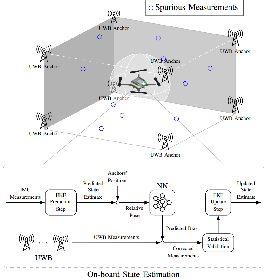
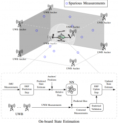
Accurate indoor localization is a crucial enabling technology for many robotic applications, from warehouse management to monitoring tasks. Ultra-wideband (UWB) localization technology, in particular, has been shown to provide robust, high-resolution, and obstacle-penetrating ranging measurements. Nonetheless, UWB measurements are still corrupted by non-line-of-sight (NLOS) communication and spatially-varying biases due to doughnut-shaped antenna radiation pattern. In our recent work, we present a lightweight, two-step measurement correction method to improve the performance of bothTWR andTDoA-based UWB localization. We integrate our method into the Extended Kalman Filter (EKF) onboard a Crazyflie and demonstrate a closed-loop position estimation performance with ~20cm root-mean-square (RMS) error.
UWB measurement errors can be separated into two groups: (1) systematic bias caused by limitations in the UWB antenna pattern and (2) spurious measurements due to NLOS and multi-path propagation. We propose a two-step UWB bias correction approach exploiting machine learning (to address(1)) and statistical testing (to address (2)). The data-driven nature of our approach makes it agnostic to the origin of the measurement errors it corrects. "
Not a drone (yet), but DIY and very well done. From Hackaday:
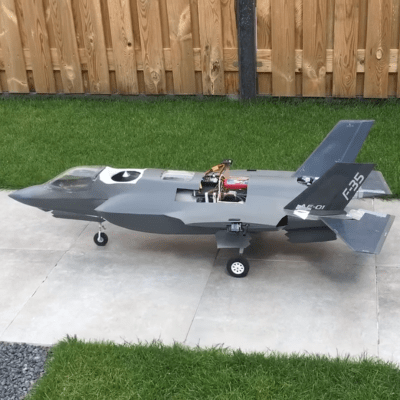
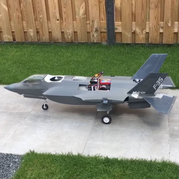
he advent of affordable gear for radio-controlled aircraft has made the hobby extremely accessible, but also made it possible to build some very complex flying machines on a budget, especially when combined with 3D printing. [Joel Vlashof] really likes VTOL fighter aircraft and is in the process of building a fully functionalradio-controlled F-35B.
The F-35 series of aircraft is one of the most expensive defence project to date. The VTOL capable “B” variant is a complex machine, with total of 19 doors on the outside of the aircraft for weapons, landing gear and thrusters. The thruster on the tail can pivot 90° down for VTOL operations, using an interesting 3-bearing swivel mechanism.
https://hackaday.com/wp-content/uploads/2020/04/2020-04-26-8.png?resize=250,250 250w, https://hackaday.com/wp-content/uploads/2020/04/2020-04-26-8.png?resize=400,400 400w, https://hackaday.com/wp-content/uploads/2020/04/2020-04-26-8.png?resize=625,625 625w" sizes="(max-width: 400px) 100vw, 400px" />[Joel] wants his model to be as close as possible to the real thing, and has integrated all these features into his build. Thrust is provided by two EDF motors, the pivoting nozzle is 3D printed and actuated by three set of small DC motors, and all 5 doors for VTOL are actuated by a single servo in the nose via a series of linkages. For tilt control, air from the main fan is channeled to the wing-tips and controlled by servo-actuated valves. A flight controller intended for use on a multi-rotor is used to help keep the plane stable while hovering. One iteration of this plane bit the dust during development, but [Joel] has done successful test flights for both hover and conventional horizontal flight. The really tricky part will be transitioning between flight modes, and [Joel] hopes to achieve that in the near future.
Humans subconsciously use perception-action loops to do just about everything, from walking down a crowded sidewalk to scoring a goal in a community soccer league. Perception-action loops—using sensory input to decide on appropriate action in a continuous real time loop —are at the heart of autonomous systems. Although this tech has advanced dramatically in the ability to use sensors and cameras to reason about control actions, the current generation of autonomous systems are still nowhere near human skill in making those decisions directly from visual data. Here, we share how we have built Machine Learning systems that reason out correct actions to take directly from camera images. The system is trained via simulations and learns to independently navigate challenging environments and conditions in real world, including unseen situations.
We wanted to push current technology to get closer to a human’s ability to interpret environmental cues, adapt to difficult conditions and operate autonomously. For example, in First Person View (FPV) drone racing, expert pilots can plan and control a quadrotor with high agility using a noisy monocular camera feed, without compromising safety. We were interested in exploring the question of what it would take to build autonomous systems that achieve similar performance levels. We trained deep neural nets on simulated data and deployed the learned models in real-world environments. Our framework explicitly separates the perception components (making sense of what you see) from the control policy (deciding what to do based on what you see). This two-stage approach helps researchers interpret and debug the deep neural models, which is hard to do with full end-to-end learning.
The ability to efficiently solve such perception-action loops with deep neural networks can have significant impact on real-world systems. Examples include our collaboration with researchers at Carnegie Mellon University and Oregon State University, collectively named Team Explorer, on the DARPA Subterranean (SubT) Challenge. The DARPA challenge centers on assisting first responders and those who lead search and rescue missions, especially in hazardous physical environments, to more quickly identify people in need of help.
The video above shows the DARPA Subterranean Challenge, one of the ways Microsoft is advancing state of art in the area of autonomous systems by supporting research focused on solving real-world challenges. Learn more aboutMicrosoft Autonomous systems.
Team Explorer has participated in the first two circuits of the challenge, taking second place in the February, 2020 Urban Circuit and first place in theSeptember, 2019 Tunnel Circuit. In the Tunnel Circuit, the robots navigated underground tunnels for an hour at a time to successfully locate hidden items. In the Urban Circuit, they navigated two courses designed to represent complex urban underground infrastructure, including stairs and elevation changes. Reasoning correct control actions based on perception sensors is a critical component to success of the mission. The current methods used by Team Explorer include carefully engineered modules, such as localization, mapping and planning, which were then carefully orchestrated to carry out the mission. Here, we share how an approach of learning to map perception data to correct control actions can simplify the system further.
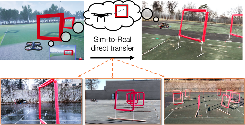
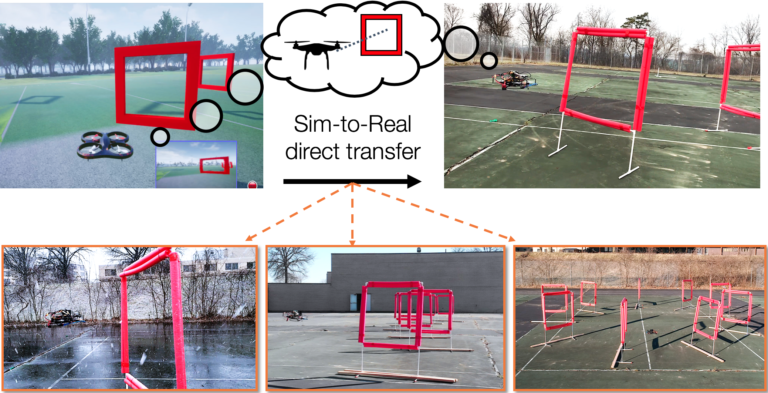
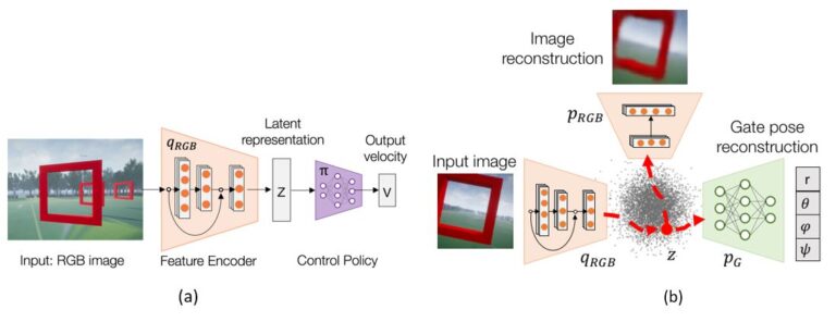
Figure 1. Our framework uses simulation to learn a low-dimensional state representation using multiple data modalities. This latent vector is used to learn a control policy which directly transfers to real-world environments. We successfully deploy the system under various track shapes and weather conditions, ranging from sunny days to strong snow and wind.
The Task
In first person view (FPV) drone racing, expert pilots can plan and control a quadrotor with high agility using a noisy monocular camera feed, without compromising safety. We attempted to mimic this ability with our framework, and tested it with an autonomous drone on a racing task.
We used a small agile quadrotor with a front facing camera, and our goal was to train a neural network policy to navigate through a previously unknown racing course. The network policy used only images from the RGB camera.
While autonomous drone racing is an active research area, most of the previous work so far has focused on engineering a system augmented with extra sensors and software with the sole aim of speed. Instead, we aimed to create a computational fabric, inspired by the function of a human brain, to map visual information directly to correct control actions. We achieved this by first converting the high-dimensional sequence of video frames to a low-dimensional representation that summarizes the state of the world.
Figure 2: Quadrotor used for the experiments. Images from the front-facing camera are processed on the onboard computer.
Our Approach
Our approach was to learn a visuomotor policy by decomposing the problem into the tasks of (1) building useful representations of the world and (2) taking a control action based on those representations. We usedAirSim, a high-fidelity simulator, in the training phase and then deployed the learned policy in the real world without any modification. Figure 1 depicts the overall concept, showing a single perception module shared for simulated and real autonomous navigation.
A key challenge here is the models have to be robust to the differences (e.g., illumination, texture) between simulation and the real world. To this end, we used the Cross-Modal Variational Auto Encoder (CM-VAE) framework for generating representations that closely bridge the simulation-reality gap, avoiding overfitting to the eccentricities of synthetic data.
The first data modality considered the raw unlabeled sensor input (FPV images), while the second characterized state information directly relevant for the task at hand. In the case of drone racing, the second modality corresponds to the relative pose of the next gate defined in the drone’s coordinate frame. We learned a low-dimensional latent environment representation by extending the CM-VAE framework. The framework uses an encoder-decoder pair for each data modality, while constricting all inputs and outputs to and from a single latent space (see Fig. 3b).
The system naturally incorporated both labeled and unlabeled data modalities into the training process of the latent variable. Imitation learning was then used to train a deep control policy that mapped latent variables into velocity commands for the quadrotor (Fig. 3a).
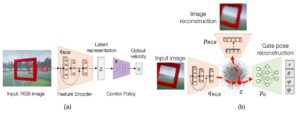
Figure 3. (a) Control system architecture. The input image from the drone’s video is encoded into a latent representation of the environment. A control policy acts on the lower-dimensional embedding to output the desired robot control commands. (b) Cross-modal VAE architecture. Each data sample is encoded into a single latent space that can be decoded back into images, or transformed into another data modality such as the poses of gates relative to the unmanned aerial vehicle (UAV).
Learning to understand the world
The role of our perception module was to compress the incoming input images into a low-dimensional representation. For example, the encoder compressed images of size 128 X 72 in pixels (width X height) from 27,648 original parameters (considering three color channels for RGB) down to the most essential 10 variables that can describe it.
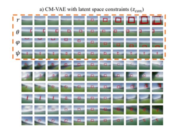
We interpreted the robot’s understanding of the world by visualizing the latent space of our cross-modal representations (see Figure 4). Despite only using 10 variables to encode images, the decoded images provided a rich description of what the drone can see ahead, including all possible gates sizes and locations, and different background information.
Figure 4. Visualization of imaginary images generated from our cross-modal representation. The decoded image directly captures the relative gate pose background information.
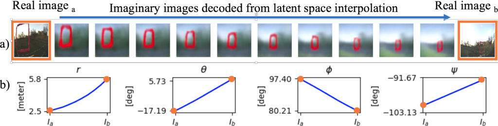
We also showed that this dimensionality compression technique is smooth and continuous. Figure 5 displays a smooth imaginary path between two images taken in real life. Given the cross-modal nature of the representation, we can see both decoded images and gate poses for the intermediate values.
Figure 5: Visualization of smooth latent space interpolation between two real-world images. The ground-truth and predicted distances between camera and gate for images A and B were (2.0, 6.0) and (2.5, 5.8) meters respectively.
Results
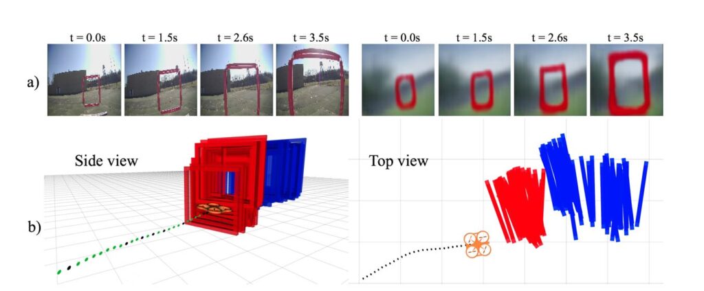
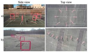
To show the capabilities of our approach on a physical platform, we tested the system on a 45-meter-long S-shaped track with 8 gates, and on a 40-meter-long circular track with 8 gates, as shown in Figure 6. Our policy using a cross-modal representation significantly outperformed end-to-end control policies and networks that directly encoded the position of the next gates, without reasoning over multiple data modalities. To show the capabilities of our approach on a physical platform, we test the system on an S-shaped track with eight gates and 45 meters of length, and on a circular track with eight gates and 40 meters of length, as shown in Figure 6. Our policy that uses a cross-modal representation significantly outperforms end-to-end policies, and networks that directly encode the position of the next gates, without reasoning over multiple data modalities.
Figure 6: Side and top view of the test tracks: a) Circuit track, and b) S-shape track.
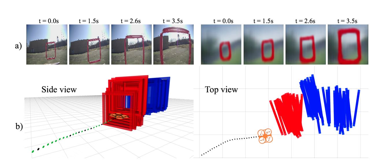
The performance of standard architectures dropped significantly when deployed in the real-world after training in simulation. Our cross-modal VAE, on the other hand, can still decode reasonable values for the gate distances despite being trained purely on simulation. For example, Fig. 7 displays the accumulated gate poses decoded from direct image to pose regression and from our framework, during three seconds of a real flight test. Direct regression results in noisy estimated gate positions, which are farther from the gate’s true location.
Fig 7. Analysis of a three-second flight segment. a) Input images and their corresponding images decoded by the CM-VAE; b) Time history of gate center poses decoded from the CM-VAE (red) and regression (blue). The regression representation has significantly higher offset and noise from the true gate pose, which explains its poor flight performance.
We take our perception-control framework to its limits by testing it in visual conditions never seen before during the training phase in simulation. Fig. 8 shows examples of successful test cases under extreme visually-challenging conditions: a) indoors, with a blue floor containing red stripes with the same red tone as the gates, and Fig. 8 b-c) during heavy snows. Despite the intense visual distractions from background conditions, the drone was still able to complete the courses by employing our cross-modal perception module.
Challenges and Future
By separating the perception-action loop into two modules and incorporating multiple data modalities into the perception training phase, we can avoid overfitting our networks to non-relevant characteristics of the incoming data. For example, even though the sizes of the square gates were the same in simulation and physical experiments, their width, color, and even intrinsic camera parameters are not an exact match. The multiple streams of information that are fed into the cross-modal VAE aid in implicit regularization of the learned model, which leads to better generalization over appearance changes.
We believe our results show great potential for helping in real-world applications. For example, if an autonomous search and rescue robot is better able to recognize humans in spite of differences in age, size, gender, ethnicity and other factors, that robot has a better chance of identifying and retrieving people in need of help.
An unexpected result we came across during our experiments is that combining unlabeled real-world data with the labeled simulated data for training the representation models did not increase overall performance. Using simulation-only data worked better. We suspect that this drop in performance occurs because only simulated data was used in the control learning phase with imitation learning. One interesting direction for future work we are investigating is the use of adversarial techniques for lowering the distance in latent space between similar scenes encoded from simulated and real images. This would lower the difference between data distributions during training and testing phases.
We envision extending the approach of using unlabeled data for policy learning. For example, besides images, can we combine distinct data modalities such as laser measurements and even sound for learning representations of the environment? Our success with aerial vehicles also suggests the potential to apply this approach to other real-world robotics tasks. For instance, we plan to extend our approach to robotic manipulation which also requires a similar ability to interpret inputs in real time and make decisions while ensuring safe operations.
All multirotor drones can be used as wind sensors, providing wind profiles on demand, anywhere, with higher spatiotemporal resolution and a fraction of the cost of other methods. See the free open-access paperhttps://lnkd.in/em95QEaon how to obtain wind profiles from the drone's dynamic response to wind-induced perturbations. The study was led by soon-to-graduateVirginia Tech
The past few years have seen tremendous progress in reinforcement learning (RL). From complex games to robotic object manipulation, RL has qualitatively advanced the state of the art. However, modern RL techniques require a lot for success: a largely deterministic stationary environment, an accurate resettable simulator in which mistakes – and especially their consequences – are limited to the virtual sphere, powerful computers, and a lot of energy to run them. At Microsoft Research, we are working towards automatic decision-making approaches that bring us closer to the vision of AI agents capable of learning and acting autonomously in changeable open-world conditions using the limited onboard compute.Project Frigatebirdis our ambitious quest in this space, aimed at building intelligence that can enable small fixed-wing uninhabited aerial vehicles (sUAVs) to stay aloft purely by extracting energy from moving air.
Let’s talk hardware
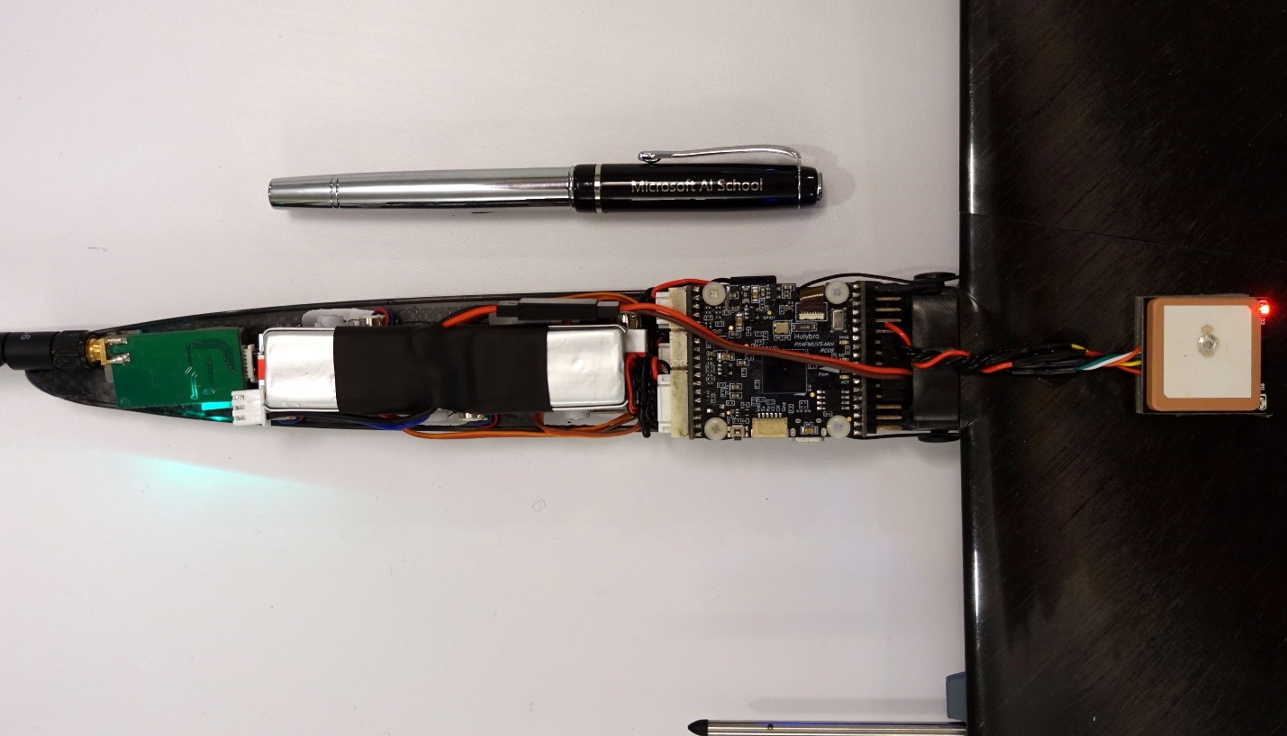
Snipe 2, our latest sUAV, pictured above, exemplifies Project Frigatebird’s hardware platforms. It is a small version of a special type of human-piloted aircraft known as sailplanes, also called gliders. Like many sailplanes, Snipe 2 doesn’t have a motor; even sailplanes that do, carry just enough power to run it for only a minute or two. Snipe 2 is hand-tossed into the air to an altitude of approximately 60 meters and then slowly descends to the ground—unless it finds a rising air current called a thermal (seeFigure 2) and exploits it to soar higher. For human pilots in full-scale sailplanes, travelling hundreds of miles solely powered on these naturally occurring sources of lift is a popular sport. For certain birds like albatrosses or frigatebirds, covering great distances in this way with nary a wing flap is a natural-born skill. A skill that we would very much like to bestow on Snipe 2’s AI.
Figure 1: the layout of hardware for autonomous soaring in Snipe 2’s narrow fuselage.
Snipe 2’s 1.5 meter-wingspan airframe weighs a mere 163 grams, its slender fuselage only 35 mm wide at its widest spot. Yet it carries an off-the-shelf Pixhawk 4 Mini flight controller and all requisite peripherals for fully autonomous flight (see Figure 1.) This “brain” has more than enough punch to run our Bayesian reinforcement learning-based soaring algorithm,POMDSoar. It can also receive a strategic, more computationally heavy, navigation policy over the radio from a laptop on the ground, further enhancing the sUAV’s ability to find columns of rising air. Alternatively, Snipe 2 can house more powerful but still sufficiently compact hardware such as Raspberry Pi Zero to compute this policy onboard. Our larger sailplane drones like the 5-meter wingspan Thermik XXXL can carry even more sophisticated equipment, including cameras and a computational platform for processing their data in real time for hours on end. Indeed, nowadays the only barrier preventing winged drones from staying aloft for this long on atmospheric energy alone in favorable weather is the lack of sufficient AI capabilities.
Reaching higher
Why is building this intelligence hard? Exactly because of the factors that limit modern RL’s applicability. Autopilots of conventional aircraft are built on fairly simple control-based approaches. This strategy works because an aircraft’s motors, in combination with its wings, deliver a stable source of lift, allowing it to “overpower” most of variable factors affecting its flight, for example, wind. Sailplanes, on the other hand, are “underactuated” and must make use of – not overpower – highly uncertain and non-stationary atmospheric phenomena to stay aloft. Thermals, the columns of upward-moving air in which hawks and other birds are often seen gracefully circling, are an example of these stochastic phenomena. A thermal can disappear minutes after appearing, and the amount of lift if provides varies across its lifecycle, with altitude, and with distance from the thermal center. Finding thermals is a difficult problem in itself. They cannot be seen directly; a sailplane can infer their size and location only approximately. Human pilots rely on local knowledge, ground features, observing the behavior of birds and other sailplanes, and other cues, in addition to instrument readings, to guess where thermals are. Interpreting some of these cues involves simple-sounding but nontrivial computer vision problems—for example, estimating distance to objects seen against the background of featureless sky. Decision-making based on these observations is even more complicated. It requires integrating diverse sensor data on hardware far less capable than a human brain, and accounting for large amounts of uncertainty over large planning horizons. Accurately inferring the consequences of various decisions using simulations, a common approach in modern RL, is thwarted under these conditions by the lack of onboard compute and energy to run it.
Figure 3: (Left) A schematic depiction of air movement within thermals and a sailplane’s trajectory. (Right) A visualization of an actual thermal soaring trajectory from one of our sUAVs’ flights.
Our first steps have focused on using thermals to gain altitude:
OurRSS-2018 paperwas the first autonomous soaring work to deploy an RL algorithm for exploiting thermals aboard an actual sailplane sUAV, as opposed to simulation. It also showed RL’s advantage at this task over a strong baseline algorithm based on control and replanning, an instance of a class of autonomous thermaling approaches predominant in prior work, in a series of field tests. Our Bayesian RL algorithm POMDSoar deliberatively plans learning about the environment and exploiting the acquired knowledge. This property gives it an edge over more traditional soaring controllers that update their thermal model and adjust their thermaling strategy as they gather more data about the environment, but don’t take intentional steps to optimize the information gathering.
OurIROS-2018 paperstudied ArduSoar, a control-based thermaling strategy. We have found it to perform very well given its approach that plans based on the current most likely thermal model. As a simple, robust soaring controller, ArduSoar has been integrated intoArduPlane, a major open-source autopilot for fixed-wing drones.
Figure 4: An animated 3D visualization of a real simultaneous flight of two motorized Radian Pro sailplanes, one running ArduSoar and another running POMDSoar. Use the mouse to change the viewing angle, zoom, and replay speed. At the end, one of the Radians can be seen engaging in low-altitude orographic soaring near a tree line, getting blown by a wind gust into a tree, and becoming stuck there roughly 35 meters above the ground – a reality of drone testing in the field. After some time, the Radian was retrieved from a nearby swamp and repaired. It flies to this day.
Although Project Frigatebird’s goal is to take RL beyond simulated settings, simulations play a central role in the project. While working on POMDSoar and ArduSoar, we saved a lot of time by evaluating our ideas on a simulator in the lab before doing field tests. Besides saving time, simulators allow us to do crucial experiments that would be very difficult to do logistically in the field. This applies primarily to long-distance navigation, where simulation lets us learn and assess strategies over multi-kilometer distances over various types of terrain, conditions we don’t have easy access to in reality.
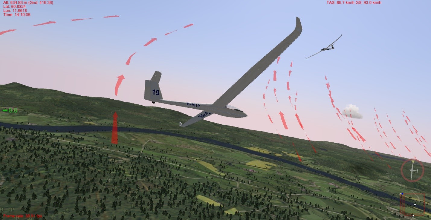
Figure 5: Software-in-the-loop simulation in Silent Wings. A Frigatebird-controlled LS-8b sailplane is trying to catch a thermal where another sailplane is already soaring on a windy day near Starmoen, Norway. For debugging convenience, Silent Wings indicates the centers of thermals and ridge lift, which are invisible in reality, with red arrows (this visualization can be disabled).
To facilitate such experimentation for other researchers,we released a software-in-the-loop (SITL) integrationbetween Frigatebird and a soaring flight simulator,Silent Wings. Silent Wings is renowned for the fidelity of its soaring flight experience. Importantly for experiments like ours, it provides the most accurate modelling of the distribution of thermals and ridge lift across the natural landscape as a function of terrain features, time, and environmental conditions that we’ve encountered in any simulator. This gives us confidence that Silent Wings’ evaluation of long-range navigation strategies, which critically rely on these distributions, will yield qualitatively similar results to what we will see during field experiments.
Flight plan
Sensors let sailplane sUAVs reliably recognize when they are flying through a thermal, and techniques like POMDSoar let them soar higher, even in the weak turbulent thermals found at lower altitudes. However, without the ability to predict from a distance where thermals are, the sailplane drones can’t devise a robust navigation strategy from point A to point B. To address this problem, in partnership with scientists fromETH Zurich’s Autonomous Systems Lab, we are researching remote thermal prediction and its integration with motion planning.
Thermals appear due to warmer parts of the ground heating up the air above them and forcing it rise. Our joint efforts with ETH Zurich’s team focus on detecting the temperature differences that cause this process, as well as other useful features from a distance, using infrared and optical cameras mounted on the sailplane, and forecasting thermal locations from them (seeFigure 6.) However, infrared cameras cannot “see” such minute temperature variations in the air, and not every warm patch on the ground gives rise to a thermal, making this a hard but exciting problem. Integrating the resulting predictions with reinforcement learning for motion planning raises research challenges of its own due to the uncertainty in the predictions and difficulties in field evaluation of this approach.
Figure 6: A schematic of a sailplane predicting thermal locations in front of itself by mapping the terrain with infrared and optical cameras. Image provided by ETH Zurich’s Autonomous Systems Lab.
Crew
Building intelligence for a robotic platform that critically relies on, not merely copes with, highly variable atmospheric phenomena outdoors so that it can soar as well as the best soarers – birds! – takes expertise far beyond AI itself. To achieve our dream, we have been collaborating with experts from all over the world.Iain Guilliard, a Ph.D. student from the Australian National University and a former intern at Microsoft Research, has been the driving force behind POMDSoar.Samuel Tabor, a UK-based autonomous soaring enthusiast, has developed the alternative control-based ArduSoar approach and helped build the software-in-the-loop integration for Silent Wings. TheFrigatebird autopilot, which includes POMDSoar and ArduSoar, is based on the ArduPlane open-source project and on feedback from the international community of its developers. We are researching infrared/optical vision-aided thermal prediction with our partnersNicholas Lawrance,Jen Jen Chung,Timo Hinzmann, andFlorian AchermannatETH Zurich’s Autonomous Systems Labled byRoland Siegwart. The know-how of all these people augments our project team’s in-house expertise in automatic sequential decision-making, robotics/vision (Debadeepta Dey), and soaring (Rick Rogahn).
 https://dronedj.com/wp-content/uploads/sites/2/2021/11/Rehm.jpg?resize=155,86 155w, https://dronedj.com/wp-content/uploads/sites/2/2021/11/Rehm.jpg?resize=655,364 655w, https://dronedj.com/wp-content/uploads/sites/2/2021/11/Rehm.jpg?resize=768,426 768w, https://dronedj.com/wp-content/uploads/sites/2/2021/11/Rehm.jpg?resize=1024,568 1024w, https://dronedj.com/wp-content/uploads/sites/2/2021/11/Rehm.jpg?resize=1536,853 1536w, https://dronedj.com/wp-content/uploads/sites/2/2021/11/Rehm.jpg?resize=2048,1137 2048w" alt="" />

 The changes between the frames


