These aren't drones per se, but I can help but post this story by Owen Churchill in Sixthtone, which exemplifies the DIY spirit.
CHONGQING, Southwest China — Dismembered remote-controlled airplanes lie strewn across an unmade mattress: a motor glued crudely into an improvised wooden housing, landing gear fashioned out of a metal ruler, and sheets of foam advertising board that will become wings, fuselages, and flaps.
This is the spare room of Hu Bo, an 18-year-old from a village two hours from Chongqing who has turned his hand to making flyable models of China’s home-grown aircraft. He started with decades-old military planes and has recently worked on the new flagbearer of the country’s civil aviation industry, the C919 passenger jet. Using self-taught techniques, open-source plans downloaded from the internet, and cheaply acquired or improvised parts, Hu sells his finished models online — unless he crashes them during the test flight. “My technique isn’t so good,” he tells Sixth Tone with a smile as he tinkers with his latest build, a 1.4-meter-wide, twin-propeller plane modeled on China’s Y-12 utility aircraft.
Like millions of other Chinese children, Hu grew up under the guardianship of his grandparents while his parents traveled in search of work, dividing his time between doing homework, playing with the family’s dog, and making intricate paper airplanes at the family home in Yangliu Village, a tiny hamlet around 100 kilometers west of Chongqing.
But now, having scraped together money to buy some basic tools, Hu has joined the ranks of China’s rising number of amateur aviation enthusiasts, spurred on by a huge yet inconsistently regulated drone industry and inspired by the increasing prowess of the country’s home-grown fleet of both military and civilian aircraft. A number of fifth-generation fighter jets are slated to enter service in the next few years; the maiden flight of the world’s widest seaplane — the AG600 — is scheduled for this year; and the country’s first large passenger jet in decades, the C919, took to the skies for the first time on May 5, catalyzing the emergence of a new generation of patriotic plane spotters despite its plethora of foreign parts.
Hu has never been on a plane, nor has he ever purchased a complete remote-controlled plane. While he was inspired to start building planes after seeing local friends discussing the latest and best modeling equipment on social media, he has little respect for people who throw money at the hobby. “They are all renminbi fliers,” he says, referring to China’s monetary currency. “For poor people like us, we have time but no money, so we have to make it ourselves. For them, they have money but no time, so they just buy everything outright.”
Buyers on Xianyu — the secondhand version of China’s premier online marketplace, Taobao — have already praised the caliber of Hu’s models, especially the C919. But at least for now, Hu has little interest in making a profit from his planes — if he believes the buyer is a genuine plane enthusiast who will cherish his models, he doesn't charge much more than the cost of the materials, making around 60 yuan (just under $9) for up to a week’s work.
It’s barely a living wage, and it does little to ease the acute financial pressure that his family currently faces. Six months ago, Hu and 22-year-old Xu Xifang became parents. Hu introduces Xu as his wife, but you won’t find their names on any of China’s marriage records: At 18, Hu is still four years away from the country’s marriageable age for men. Also in the family home is his 8-year-old sister and their 65-year-old grandmother, who works 12-hour shifts at a local waste collection plant for 50 yuan per day.
He may barely be covering his costs, but for Hu, building and flying planes has provided welcome respite to the desperate pursuit of livelihood that has defined his childhood. At 14, he quit school to join his parents in China’s southern Guangdong province to work in a brick factory, where he stayed for four years before returning to his home village to settle down and start a family.
“I don’t want my son to be like me,” Hu says, reflecting on his own experience of living without his parents. “No matter where I am, whether I do manual work or business, whether I have nothing at all, I will always stay beside him.”
Indeed, Hu’s pastime-cum-business has become something of a family affair, with his wife, Xu, helping out when she can with printing and cutting the plans. “At the beginning, I didn’t like that he was doing this — I didn’t think he had any hope,” she says as she slices around the cockpit of a C919. “But then I watched him doing it and saw that he was so happy, so I just let him keep going.”
As Hu squats on the floor putting the final touches on his Y-12, his 6-month-old son An An looks on, engrossed, even reaching out from time to time to prod a wing or grab a propeller. A cool breeze one recent afternoon brought a brief lull in the stifling heat and meant that Hu could take his son up into the hills that surround their home to witness the plane’s maiden flight. “The look in his eyes when he sees a model plane is different to when he sees other toys,” says Hu, back in the house after an accident-free test flight. “Today, I saw that look.”
Hu has high hopes for his son. By the time Hu is 30, he wants to have built a plane that he himself can fly in, a project he says he will need his son’s help with. But his aerospace aspirations for An An don’t stop there. “My grandfather made wheelbarrows, my dad made little toys, and now I make airplanes,” he says. “I think my son will take the next step and make satellites.”
For now, Hu may have to concern himself with matters closer to home. Until recently, Hu had been free to fly what he wanted, where he wanted. But that looks set to change, as local authorities around the country scramble to limit the use of remote-controlled aircraft following a series of close encounters between drones and passenger jets. One of the most recent occurred at nearby Chongqing’s Jiangbei Airport, when two instances of drone interference were reported in one evening.
Hu calls it a “day of sadness” for model plane enthusiasts like him. Since the incident, local authorities have stipulated that all model plane fliers must submit their personal information and aircraft specifications to a local government representative. Such restrictions appear to be more stringent than the drone-focused regulations currently being rolled out nationwide, which do not mention fixed-wing model airplanes. Flying zones are also being restricted, and now the nearest designated area to Hu’s home is 50 kilometers away.
Despite his sadness, Hu calls the restrictions reasonable and vows that he would never flagrantly violate them. His recent test flight of the Y-12 in the nearby hills was an exception, he says, explaining that he made sure to control his height, speed, and distance. “Even a bird can be dangerous if it strikes an aircraft,” he says, “let alone a drone weighing 10, 20 kilograms.”
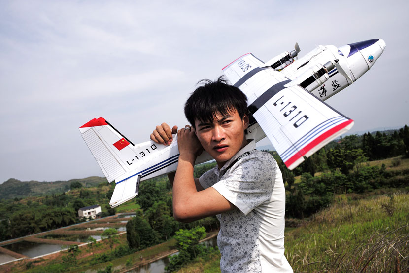
Hu Bo carries his model Y-12 aircraft after taking it out for a flight in Dazu County, Chongqing, May 16, 2017. Wu Yue/Sixth Tone
Regulations aside, there are other matters that stand in the way of Hu’s passion. His parents recently moved from Guangdong to Chengdu in Chongqing’s neighboring Sichuan province to join a relative’s wholesale grocery company. Hu has been earmarked as one of the company’s delivery drivers, and so has spent the last few weeks preparing for his driving test.
The day after the maiden flight of Hu’s Y-12, he and Xu made the 230-kilometer bus ride to Chengdu, leaving behind Hu’s grandmother and sister. True to his vow never to leave his son, Hu has taken An An with him; true to his passion, Hu has also taken some basic tools and the plans for a massive, 2.4-meter-wide model of China’s new military transporter, the Y-20, despite the fact that he’ll struggle to find anywhere in the metropolis of Chengdu to fly it.
“If I go a day without making planes, then I feel like a smoking addict who hasn’t had a cigarette,” says Hu. One day, he says, he’ll harness that addiction and open a small workshop with a few employees making several planes a day. “That way, my family can have a better life.”


/cdn0.vox-cdn.com/uploads/chorus_asset/file/8147113/qvuclrk6dqzmvh0slix3.jpg)


