After a few months of hard work, SplineNav 0.3 is now ready to fly! This SplineNav release started with the goal of simply reducing the yaw jitter issues of SplineNav 0.2, but in the end it turned into a major rewrite of the code.
New Features:
- Smoother Yaw: Updates x and y spline derivative calculations faster, in a separate loop, for a more precise yaw control. Uses a fast approximation of the atan2 function to compute the yaw angle from the spline derivative.
- Features yaw rate smoothing for much smoother video, avoiding the small yaw "jerk" at each waypoint.
- Allows manual override of yaw control, then takes back auto control of yaw if the pilot centers the stick when yaw is directed approximately in the direction of the spline curve.
- Now enters SplineNav mode smoothly, without an initial jerk.
- Uses it's own flight mode, so unlike SplineNav 0.2 it doesn't override your Circle mode. To use SplineNav 0.3, set one of your FLTMODE parameters to 14 in the Full Parameter List.
SplineNav Waypoints
We collected the waypoints for this video while flying FPV, and flipping the channel 8 switch at each point to record. Then we loaded the waypoints into Mission Planner, and made some small adjustments:
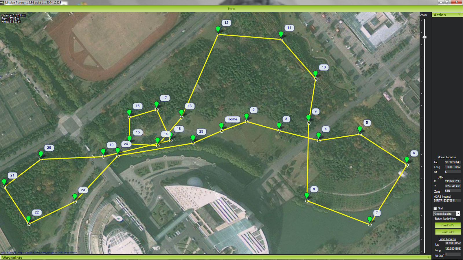 |
| Waypoints recorded during FPV flight and adjusted in Mission Planner |
The GPS track indicates it hit all the waypoints quite precisely, on each lap for a total of 3 laps (72 waypoints in total):
 |
| GPS track from dataflash log shows SplineNav hitting each waypoint precisely over 3 complete laps |
The waypoints had a range of altitudes set, from 7 to 35 meters. Here is the flight profile from the autopilot logs, imported into Google Earth:
 |
| GPS flight profile from dataflash logs after 3 complete laps |
Hardware Used:
Airframe: 3D Robotics Quad, with some modifications.
Autopilot: 3DR APM 2.6, with external compass/GPS module
Motors: T-Motor MT2216 KV800
Props: APC 11x4.7
Gimbal: WIND-1 two-axis brushless
Camera: GoPro Hero 3 Silver
Telemetry: 3DR 433 MHz
R/C: FlySky TH9X(ER9X FW) + 2.4GHz FrSky DJT module + V8R7-II rx
FPV: ImmersionRC 5.8GHz 600mA + FatShark Predator + SecurityCamera2000 CMQ1993X
Also: These mods for longer range FPV.
SplineNav 0.3 Firmware Installation:
- First make sure your quad copter is flying well with ArduCopter version 3.0.1, since SplineNav 0.3 is based on this firmware version.
- Go to https://github.com/mavbot/SplineNav, and click the "Download ZIP" link.
- In the special Ardupilot version of Arduino, go to File -> Preferences and set your sketch directory to the path of the "SplineNav-SplineNav-0.3" directory from the extracted zip archive.
- Restart Arduino, then choose File -> Sketchbook -> ArduCopter from the menu.
- From the ArduPilot menu, make sure your HAL Board is set correctly.
- Connect your copter's APM via USB, and from Arduino's Tools menu make sure the serial port is set correctly.
- Click the Upload arrow button and wait for the code to compile and upload to your APM.
- Set one of your FLTMODE parameters to 14 in Mission Planner's Full Parameter List, set your waypoints (either with Mission Planner or with the channel 7 or 8 switch), then go fly!
Note: If you have any special requirements, such as a frame or orientation other than quad X, remember to make those adjustments in the code before compiling. Or if you'd rather not compile yourself, please contact us to get a hex file you can upload directly via Mission Planner.
Parameters
Here are the speed and acceleration parameters we used for this video (set in Mission Planner):
WPNAV_SPEED: 1350 cm/s
This should make SplineNav go about 49 km/h on straight segments.
WPNAV_SPEED_UP: 1000 cm/s
WPNAV_SPEED_DN: 650 cm/s
WPNAV_LOIT_SPEED: 1500 cm/s
Should be set higher than WPNAV_SPEED.
WPNAV_ACCEL: 180 cm/s/s
Nice low value for a smooth steady start.
Also, the following parameters are #defines in the splinenav.h source code, and can be changed at compile time:
SPLINE_TENSION: 1.6
Higher tension splines curve more tightly at waypoints, but straighter in between waypoints. A tension value of 2 makes it a Catmull-Rom spline. We found that slightly lower tensions tend to give nice loose curves for smooth aerial video.
SPLINE_CURVE_ACCEL_MULTIPLE: 2.0
This allows for twice the max curve acceleration as set in the WPNAV_ACCEL parameter. Added this parameter to allow for smooth slow starts without making tight curves overly sluggish.
SPLINE_JERK: 200.0 cm/s/s/s
Jerk is the maximum rate that SplineNav increases or decreases acceleration as it flies the curve.
SPLINE_LOOP: true
This makes SplineNav loop the waypoints forever until you exit out into another mode.


