Hugues's Posts (85)

Sort by
MR60

X-UAV Clouds build part 3

This is part3 and the final assembly stage of the X-UAV Clouds build

It is equipped with  a barebone Pixhawk autopilot (from Jordi Munoz co founder 3DR, Mrobotics.io) running the latest Arduplane code,

and no need to say this is the best of all ! (thx Tridge and Randy and all others I miss). I will publish the maiden flight which is an auto take-off, fully automated : just put the radio Tx aside, throw your plane. It flies by itself. I still find this amazing even after a few years in this hobby. We now just need drones that assemble themselves, it would be less work.


Check the previous build videos,
X-UAV Clouds Build - Part1: Wings : https://youtu.be/3CkiUq-qIeU

X-UAV Clouds Build - Part2 : Motor-prop-battery combo choice : https://youtu.be/YAFJJnHktCo

Read more…
MR60

XUAV Clouds build part 2 :

Clouds is a twin motor UAV. Total weight with full payload could get as high as 4Kg.
For an easy hand or catapult launch, a 1:1 weight/power ratio would be more than enough.
This means using two motors producing each a maximum thrust in the 1.8-2Kg range.

So what motor, propellers, battery voltage then to use ?

Check the previous build video,
XUAV Clouds Build - Part1: Wings : https://youtu.be/3CkiUq-qIeU

Read more…
MR60

XUAV Clouds build part1 : Wings

"XUAV Clouds" is the latest FPV/Survey platform from XUAV. I suppose XUAV wants to capitalize on the legendary success of their V-tail Talon model and at the same time compete in the twin motor category against the popular "MFD MyTwinDream" fpv plane.

Its wing span is 1880 mm (vs 1700 on the Talon without wing extensions, or 2000mm with extensions), it has a huge payload capacity in the fuselage (in some ways better thought than in the Talon) and keeps a V-tail setup.

Much improvements are made in detachable V-tails, detachable wings with plastic joiners which the Talon model did not have. Also an integrated PET shield for belly landings, external wing ESC compartments (nice to keep heat out of the payload bay).

This video is a first part of the build with a focus on wings preparation.

You might be also interested in an overview of this plane here:

Read more…
MR60

Hello,

Here a shared review of a quite cute and tiny FPV quad, the QX90.

It was unfortunately delivered to me with a built in DSM type receiver so I could not use it with my Taranis radio.

I therefore modded the electronics with another tiny board that is incredible : it integrates a F3 flight controller with all bells and whistles plus an integrated FrSky compatible receiver !

I still have some stability issues with the receiver and Taranis. I am troubleshooting with the maker of this board and will post a follow up later on.

Read more…
MR60

190 size FPV racer build & review from GEP

Hi,

A 190 size FPV racer kit review from the GEP brand (so called ZX5 model). What's different about the previous FPV racers build I did before is a X frame while my former builds were always made with a classical H frame.

X frames have an advantage over H frames in that they are more symetrical (useful in FPV racing) and they twist much less along the central beam : that is a better Yaw control in racing.

Issue though with an X frame in a small FPV racer is the lack of room to setup all of the electronics.

Also beware when buying those kits: I noticed during the build that the provided camera was not meant for the holes designed in the camera carbon fiber plates (camera models evolve so fast and there are no dimension standards yet).

Overall we notice a good level of maturity in this kit and suppliers that obviously listen and learn from the field experience.

Links are available in the youtube video description.

Cheers

Read more…
MR60

DALRC XR215 V2 FPV Racer Build

Hi,

As a follow up of my latest blogs about FPV hardware, here is a build video. The build is made with the following components:


-DALRC XR215 V2 Full Carbon Fiber Quad Frame for FPV Racing FPV Build in OSD BEC BB Ring: http://goo.gl/dcIW2V

-Foxeer XAT600M DC5V-22V 600tvl Sony Super HAD CCD FPV Camera: http://goo.gl/ETYdS0

-Gearbest kindly provided motors for this project, Emax RS2205 2300KV Racing Edition : http://goo.gl/mV4P5h

-ESCs are taken from Gearbest's Flycolor Fairy Series V2 20A BLHeli ESCs : http://goo.gl/RU8b36

-F3 Flight controller Deluxe was kindly provided by Gearbest for this build : http://goo.gl/CDDK3C

-Propellers are DALprop J5040 : http://goo.gl/huUCeE

-ESC firmware is BLHeli with oneshot125 downloaded and flashed with the BLHeliSuite software (latest version)

-F3 flight controller firmware is Betaflight (latest version) downloaded and installed via the Betaflight configurator (Chrome app)

Music by Kevin MacLeod - site = http://incompetech.com/

Disclaimer : no chickens were hurt in the making.

Read more…
MR60

Hi,

This is a hardware review of an interesting product for FPV racers. I do not know for how long it exists but I could not find any other reviews on youtube.

This product consists in an integration of mutliple components you would otherwise need to solder and assemble together with lots of wiring, thus saving weight and making a cleaner build.

In brief, it is at the same time:

-a F3 flight controller board (could have been the latest F4 generation but hey, F3 is good enough for my flying skills). The F3 board plugs/unplugs from the ESCs/PDB motherboard. So it can be replaced if needed.

-a power distribution board

-a 5V BEC

-a 12V BEC

-4 in 1 20 amps BLHeli ESCs. Their signal+ground wires are connected to the F3 board within the PCB , so no wires required. All four ESCs can also be individually replaced if needed.

The video shows all positive and negative aspects I found about it. A big plus is the weight saving and ease of build. The biggest negative point is you are stuck with a rectangular form factor and the solder pads for the motor wires are not best placed for a typical FPV X frame.

Cheers

Hugues

Read more…
MR60

I was going to refresh my old FPV 250 racer built two years ago with an "old" Naze board and an "old" baseflight firmware. Not surprisingly, the whole firmware landscape has changed dramatically and I had to investigate quite a bit to bring me up to date with current states of affairs (lots of new firmware versions, new flight controller hardware).

As opposed to software (r)evolutions, flight controllers hardware did not evolve as much (apart from processing power increase, nothing revolutionnary). One noticeable novelty on hardware level is the relatively new open source "SP racing F3" board. Made a quick tech review of this board in the video which, as I understand it, became the state of the art flight controller for "seriously pro" FPV racers.

This video also shares some brief historical & evolution about hardware/firmware for FPV racing (MultiiWii evolution branch).

Cheers,

Hugues

Read more…
MR60

Anti Jello mount for Mobius brushless gimbal

To suppress vibrations & jello in videos taken by very lighweight camera brushless gimbals is a challenge as none of the classical methods are working well. The more weight, the easier it is to manage vibrations. When you combine extreme lightweight gimbal with a CMOS sensor technology, you'll get very prone to the so called "jello" effect.

In this video I share some findings about what works best with my 50 gr 2-axis Mobius gimbal.

The ship itself is my Subonekilo quadcopter project (800g actually with battery) which I blogged about previously. It runs Arducopter on Pixhawk, 9 " props, 3S battery.

ps : no chickens were hurt in the making of this video.

Cheers,

Hugues

Read more…
MR60

Recent 3DR's move not to sell DIY components & parts anymore, pushes hobbyists and prosumers to diversify their supplier's sources.  Like many others in the community, my issue is to find an "as good quality as 3DR" alternative for a Pixhawk board.  I started looking around for possible 3DR Pixhawk replacement candidates, with a quality I can trust in my builds. 

There exist myriads of different "Pixhawk" equivalent boards. Most of them are not direct drop-in replacements as they are equipped with different connectors and have different sizes and shapes. Furthermore, most of them do not share the same quantity and redundancy of sensors (i..e.: two gyro, two accel, compass, baro, etc). A direct drop-in replacement is essential for prosumers and professionals trying to standardize parts, connections and components to a maximum.

Then, I was kindly requested by Gearbest to review some of their new FPV racer quad; offer which I declined being a very poor racer pilot (wouldn't have made justice to their fpv quad), proposing them instead to review their Pixhawk board which looked to be an exact match for 3DR Pixhawk board on all aspects: schematics, size, shape, connectors, etc.

This is what this video is about : a test, review and comparison of Gearbest's Pixhawk (versus 3DR's Pixhawk).

Hope this will provide some useful info for who's looking for Pixhawk flight controllers.

Cheers,

Hugues

Read more…
MR60

Sub One Kilo project

Hi,

In Belgium, our local "FAA", the so called "DGTA" (as painful as in the US) has just passed last week a law regulating the use of drones. They defined a number of categories among which the "all-up-weight" of the ship is a criterion. Among the categories, a ship under a kilogram does not require a pilot certification nor all of the administrative burdens & associated costs. They allow you to fly a sub kilogram ship (except in public spaces) up to 10 meters (basically it is considered a "toy" under a kilogram).

So, this was my motivation to try to build a "Subonekilo" ship, based on Arducopter (with all the goodies including autonomous flight capability), embarking a full HD camera on a 2 axis gimbal. All of it, battery included, under a kilogram.

The ship built in this video does just that, with a flight endurance of 33 minutes @850grams without camera. It weighs just about a kilogram with a Mobius installed on my previously designed 45gr 2-axis Alexmos Mobius gimbal (see video here :45g Mobius gimbal ).

Forrest Frantz, we all know here, is the inspiration of the antivibration "struts" I'm using in this build, which is a way to isolate the frame from a platform holding all of your electronics, flight controller and battery (for maximum weight and thus minimum vibration amplitude) resting on anti-vibration isolators/dampeners. As a result, I get extremely low vibrations on all three axis X, Y, Z (see end of video for chart).

Last but not least, a big thx to our divine Ardupilot DEVs to provide such an excellent autopilot. Note that the flight shown in the video is done with the latest APM:copter 3.3.3 out-of the-box without any tuning , standard params (it wobbles a bit as the ship is way overpowered, hovering at 35%-40% => I have to lower Roll/Pitch P rate and maybe a bit D also).

A part2 will come once I've some nice video footage to show with the gimbal+Mobius (some fiddling still needed + ship tuning).

Cheers,

Hugues

Read more…
MR60


Hi, I bought these very cheap hobbyking rectangular carbon tubes. I made this not so serious experiment with them as they could potentially be great to build your own multicopter frames. Tridge, by the way, used those recently in his quadplane build he posted about on diydrones.

And, this is a not so serious contribution to coming Easter chickens...

Enjoy Easter everyone!

Hugues

Read more…
MR60

Sony QX10 mod for remote wire shutter trigger

The Sony QX10 is a nice lightweight 18 MegaPix camera for very little money (mine cost less than 100$ online, shipping included). It looks like a good one for aerial mapping missions. Unfortunately, it does not support USB cable remote triggering (unlike the much more expensive models in the QX family). Also, a smartphone app allows to trigger the camera via Wifi but that does not allow a direct shutter trigger control via Pixhawk, which was the purpose for getting this camera. Therefore I decided to modify my QX10 to see how trigger wires could be directly hacked on it...

Read more…
MR60

Hi,

The project's idea is to use my newly received (thx Santa) Pebble time smartwatch to send commands to a drone from your wrist, via a telemetry (mavlink). Accesorily, the objective is also to play with dronekit (mavlink communcation library) and SITL (APM vehicles/drones simulation tool).

As a summary, Pebble runs an HTTP client app to connect to an ESP8266 WiFi web server, which in turns transmits the received commands to the serial port of mission planner (or any other mavlink compatible ground station), running a dronekit python script to remote control the drone.

The chain of command from the Pebble watch to the drone is the following:

1.Pebble watch <=> 2. ESP8266 WiFi/UART device <=> 3.Dronekit python script <=> 4.Telemetry mavlink radio link <=> 5.Flying Drone

1. Pebble time smartwatch:

3689676400?profile=originalFrom the Pebble app store, the free "Send message" app is used as an HTTP client; The app is used as a kind of REST control, by getting (http GET) a different URI associated to different command. In this project, I decided to code three vehicle mode changes : RTL, LAND, POSHOLD.

2. Web Access Point for the Pebble - ESP8266 module:

This Pebble app needs to connect to a Web server. For that I use an ESP8266 module. As described on Sparkfun : "The ESP8266 WiFi Module is a self contained SOC with integrated TCP/IP protocol stack that can give any microcontroller access to your WiFi network. The ESP8266 is capable of either hosting an application or offloading all Wi-Fi networking functions from another application processor.". It contains a microcontroller which is twice as fast as a basic Arduino board (80 Mhz or 160 Mhz), up to 2MB of flash memory. it exposes a number of GPIO PINs for digital and analog input/ouputs and two  UART ports ! So it is possible to use this device to make a UART-WiFi bridge, which we are using in this project.

Such an ESP8266 module costs between 5 and 15 dollars according to the manufacturer & version. There are more than 12 different versions (ESP-01 is the basic standard module, ESP-02, ..., ESP-12 exposes all GPIO PINs, etc...)

3689676175?profile=original

For this project, I used the Sparkfun "Thing" version, which provides an integrated 3.3V regulator, Lipo battery input and a micro USB port.

3689676335?profile=original

The module is programmed with the well known Arduino IDE.

I programmed PebbleArducopterControlAP.ino as a web server to run on it, waiting for a Pebble smartwatch connection.

This ESP8266 converts and transmits the Pebble watch received HTTP GET commands to the serial (FTDI USB) port of the computer running a dronekit python script.

3. Dronekit python script:

The ESP8266 module forwards the smartwatch commands to a computer on a serial port (could be a computer board such as RPi or Odroid, etc).

For ease of development & testing, the well known SITL APM simulation software is used to simulate an APM:Copter version 3.3. In the SITL copter simulation, the vehicle's mavlink communicates by default via a TCP link (127.0.0.1:5760)

A quick and simple test script listens on one side on the ESP8266 web server (serial port) and , if it recognizes a programmed command, sends it out to the (SITL simulated) drone via MAvlink on the telemetry link (TCP port).

My source code of this python script here (Vehicle_SIM.py).

4. Mavlink links:

I wanted to run Mission planner in parallel to my dronekit script, to have an easy and familiar visualization of the Pebble command's results on the drone. However in order to run in parallel, on the same drone mavlink link, both the dronekit script and mission planner, you need to run MavProxy to split the mavlink channel on two different UDP ports. Full details on how to use SITL and Mavproxy is given on the dronekit.io site.

5. Flying drone - Results:

See attached video. Had lots of fun to see the magic happen : a press on one of the three Pebble watch buttons triggers a drone mode change (RTL, LAND, POSHOLD in this demo example);

Although the real practical use of such a project is doubtful, I can tell you it is a lot of fun and a good learning experience on different topics : Pebble, ESP8266 modules, Dronekit, SITL !

Cheers,

Hugues

Read more…
MR60

Build your own Antenna Tracking pan tilt system

Hi,

Willing to try out APM antenna tracking, I needed to procure myself with a mechanical servo based pan-tilt system.

This video is both a build log and a kind of "how-to" antenna tracker build guide for those who want to try build their own.

I logically first started to look around to purchase one; my market research basically resulted in solutions that I found way too expensive for what they really are : aren't we are just talking about two servos driving a pan and a tilt plate?

However, you'd have to spend a few hundreds dollars for a complete ready-to-run pan/tilt that is able to rotate medium size antennas (for example: 350+ dollars @servocity or 200+ dollars with required accessories and 180° servos @readymaderc - without shipping, EU sales taxes, or EU custom fees).

I found it really hard to source  a "1 turn" servo (there is only one model that I know of : GWS S125 but it does not seem to be produced anymore) or even a half-turn 180° servos. Most of them are standard 90° servos that were opened up to modify their internal potentiometer to extend their rotation to 180° (lots of tutorial videos on youtube explain how to do this by yourself). Alternatively, you could buy programmable digital servos but you will end up paying a high premium for them and, in addition, you will spend extra money on their proprietary programmer devices.

So the question is, is it possible to build your DIY tracker with parts you may have laying around the bench, for a very low cost ? Answer is yes, and the task can be greatly facilitated with the help of a few 3D printed parts.

I now can't wait to plug a pixhawk+GPS module on it and experiment with APM antenna tracking firmware, which will be the subject of another future blog.

PS : Here are the STL files of all the 3D printed parts used in the making of this tracker, to share with the community: Antennatracker.zip

Cheers,

Hugues

Read more…
MR60

AirbotPower board

3689667705?profile=originalFigure1 : AirbotPower board recto

3689667639?profile=originalFigure2 : AirbotPower board verso

AirbotPower introduction:

I & Nick Arsov are proud to introduce our newest product,

Airbotservices has been passionate at understanding and documenting ways to power flight controllers to ensure redundancy and maximum reliability, especially in conditions where a 4S 3DR power module (or similar PM) can’t be used: battery voltage above 4S and currents above 90 amps. Historically we published how-to guides on this topic, contributed writing documentation in the wiki and on the PX4 autopilot site:

We’ve got feedback from some who are not at ease nor have the necessary engineering skills to mess around with soldering individual electronics components, cables and connector adapters. We therefore think there is a need for proposing a high quality reliable plug and play “Power & Measure” solution, working also for higher voltages than 4S batteries.

AirbotPower solves the problem of powering a UAV and measuring current & voltage in a most high quality, reliable, redundant and efficient manner (extreme low voltage ripples, low noise, low EMI, MHz switching frequency).  It supports battery input voltages from 3S to 8S. It supports current flows up to 150 Amps. Accessorily, we provide also an AirbotPDB board (power distribution board) :
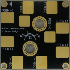
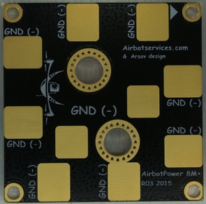
 

AirbotPDB is a companion stackable board (via XT150 connectors) for those who need a power distribution board. AirbotPower can be used standalone, without a stacked AirbotPDB board, to equip or retrofit (upgrade) a drone that already has its own PDB.

AirbotPower works to power any flight controller & FPV systems by providing triple power feeds2x 5.3V & 1x 12V (up to 3.5 amps each).  In particular, AirbotPower has been designed with Pixhawk in mind: from electronics, to voltage levels and connectors for a direct plug to Pixhawk using “off-the-shelve” servo cable and a DF13 6position cable eliminating any painstaking efforts with soldering, hacking connectors and cables.

With AirbotPower base board, comes an extra safety electronic module that plugs on Pixhawk’s servo rail: the famous Zener Diode 5.6V (5W) + capacitor. This safety module is required on Pixhawk's servo rail to trim any short voltage spikes (above 5.6V) that would be fed back to Pixhawk's servo rail from external devices & servos, which would cause Pixhawk to shutdown itself (electrical protection).

To illustrate, as concretely as possible, what AirbotPower advantages brings to your drone setup, let’s consider which individual electrical and electronic components would be required, without AirbotPower,  to optimally power a flight controller such as a Pixhawk board, while being able to measure currents up to 150 amps and supporting high voltage batteries (more than 4S) : It is a complex setup requiring the assembly and interconnections of more than a dozen of components plus messing with cables that need to be hacked, soldered, etc..  This is illustrated in figure3 below:

3689667700?profile=original

Figure 3: complexity of components and cabling to power a Pixhawk board without AirbotPower

In addition, a notorious issue is current measurement and getting stable readings. It has always been unreliable and difficult due to limitations and fragility of the main solutions that were available until now on the market : either a typical power module including current & voltage measurement (limited to 4S and 90 amps) or adding any other external INA169 chip based current measurement products (very fragile ; INA169 chip are damaged very easily by heat when soldering wires), which are producing high fluctuation measurements as soon as you have a bit of inductance or capacitance components on its output.

On figure 3, we can observe the following issues & risks:

  • More than 10 individual components
  • Standard BECs (even known brands) are noisy, have high voltage fluctuations
  • Interfacing these components requires different cables, different connectors
  • Messy cabling setup, reduces reliability as wires and connections may fail with bad soldering and vibrations
  • Difficult to maintain once assembled (buried deep between drone’s frame plates)
  • Standard quality components, even worse when sourcing from uncontrolled sources
  • Risks of wrong setup causing eventual ground loops, bad circuits, bad connections
  • No EMI, ESR protections
  • No Zener diode on Pixhawk servo rail
  • Limited voltage to 4S
  • Limited amps capacity to 90 amps


In comparison, figure 4 below shows what the situation becomes instead when using AirbotPower. It is obviously cleaner without the need for individual components soldering and messy cabling. A Pixhawk flight controller is powered with redundancy, with clean power feeds, with protection against servo rail voltage spikes, with 150 amps Hall effect current measurement, with dip-switch configurable 3S to 8S voltage measurements:
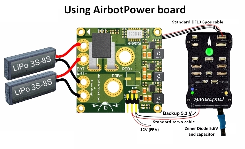
 

 Figure 4: simplicity to power a Pixhawk board with AirbotPower


AirbotPower’s functionality:

  •          2 x 5,3Volts power feeds up to 3.5 amps
  •          1 x 12 Volts power feed up to 3.5 amps (requires >=4S batteries)
  •          Equivalent of three L/C filters on each power feed
  •          Equivalent of three ferrites on each power feed
  •          Voltage spikes suppression with 5.6V Zener diode (5Watts) + Capacitor on Pixhawk servo rail
  •          HALL EFFECT current measurement (ACS758) for currents to 150 amps
  •          A dip-switch configurable 3S to 8S Voltage measurement
  •          A primary DF13 6 position connector for direct plugging into Pixhawk power port
  •          A redundant 5.3V servo connector for standard servo cabling into Pixhawk servo rail
  •          A standard 12V servo connector output for powering FPV devices
  •          Oversized double redundant parallel battery inputs (solder through pads, for 10 or 12AWG wires)
  •          Modular design separating the Power functions and the distribution function in two boards : allows to retrofit any drone already assembled with an existing Power Distribution Board (PDB). Stackable optional AirbotPDB distributionBoard, via XT150 connectors (less than 3cm height with stacked optional PDB)
  •          Large XT150 heavy duty connectors solder pads to either stack AirbotPDB or to link to an existing PDB. Flexibility to connect to PDB via connectors or soldered cables.
  •          Overcurrent, ESD and shorts protections on all three BECs
  •          No messy wiring & no cable fiddling thanks to a 6-pin DF13 output connector to connect the board to Pixhawk's 6-pin power port.
  •          Board dimensions (W x D) : 50 x 50 mm. A very compact format using standard 45x45 mm screw holes spacing (M3)
  •          Made in EUROPE, Proven Arsov design
  •          Lightweight and clean surface mount design: 21 grams


AirbotPower technical specifications highlights:

Top quality & reliable components
• Provides ultra-smooth power sources; actually they are currently the least noisy you can find on the market. We actually reached the sensitivity limits of our oscilloscope as illustrated below:
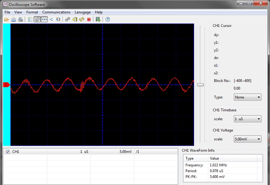
Figure5:  shows voltage ripples under a 5amps load is less than 6mv !


  •          High efficiency (91%) voltage switching regulators up to 2.2MHz operation
  •          Extremely low Voltage Output ripple < 10mV p-p
  •          Low heat generation, even at high voltages
  •          Spread spectrum frequency modulation for low EMI, low interferences
  •          ESD protection
  •          Short-circuit protection
  •          Current measurement: Robust industrial grade ACS758 Hall effect current sensor up to 150/200A which is much more reliable than the INA chip found on 3DR PM or Attopilot
  •          Voltage measurement: dip-switch selectable voltage divider for any battery voltages from 3S to 8S, optimized for a 3.3V ADC scale, therefore providing optimized measurement resolution
  •          All of three power sources have a Zener diode +capacitor protection blocks against power line ringing (external noise/ripples) and totally reduces noise to connected devices
  •          All three power sources have the equivalent of a L/C filter. We use the newest Linear Technology "QUIET" series DC-DC Bucks with less than 10mV ripple/noise, making it ultra-quiet, extremely low voltage ripple and low EMI.


Additional pictures:
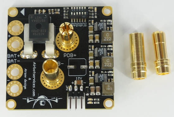
 

Figure 6: AirbotPower with XT150 connectors to stack AirbotPDB
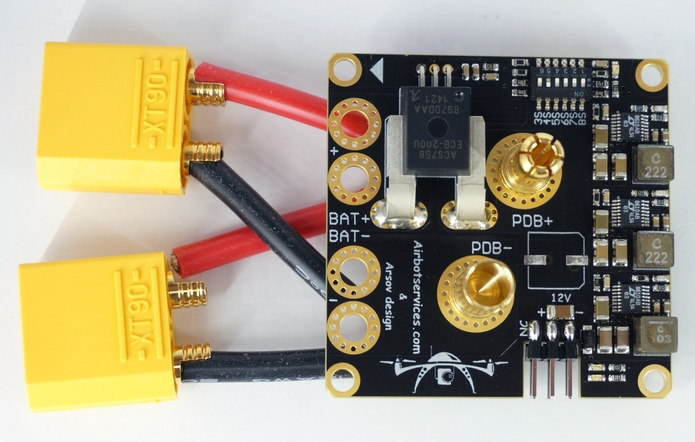

Figure 7: AirbotPower with simulated XT150 parallel battery inputs
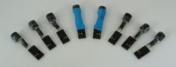
3689667762?profile=originalFigure 8 : 5.6V 5W Zener+Cap module details: plastidip & heat shrink tubing


Detailed technical specifications:

LT8610A/LT8610AB series  DC-DC bucks FEATURES DESCRIPTION :
  •          42V, 3.5A Synchronous Step-Down Regulator with 2.5microA Quiescent Current
  •          The LT8610A/LT8610AB series are compact, high efficiency, high speed synchronous monolithic step-down switching regulators that consume only 2.5microA of quiescent current.
  •          They have higher maximum output currents of 3.5A and a faster minimum switch-on time of 30ns.
  •          3.5A, 30ns, 91% efficiency
  •          3.5A Maximum Output Current
  •          Fast 30ns Minimum Switch-On Time
  •          Improved Burst Mode Efficiency (LT8610AB Only)
  •          Improved EMI and Wide Input Voltage Range: 3.4V to 42V
  •          Ultralow Quiescent Current Burst Mode. Operation
  •          Output Ripple < 10mVP-P
  •          Low Dropout Under All Conditions: 200mV at 1A
  •          Safely Tolerates Inductor Saturation in Overload
  •          Adjustable and Synchronizable Frequency: up to 2.2MHz
  •          Output Soft-Start and Tracking
  •          Small Thermally Enhanced 16-Lead MSOP Package


ACS758 CURRENT MEASUREMENT INTEGRATED IC :

  •          Industry-leading noise performance through proprietary amplifier and filter design techniques
  •          Integrated shield greatly reduces capacitive coupling from current conductor to die due to high dV/dt signals, and prevents offset drift in high-side, high voltage applications
  •          Total output error improvement through gain and offset trim over temperature
  •          Small package size, with easy mounting capability
  •          Monolithic Hall IC for high reliability
  •          Ultra-low power loss: 100 µO internal conductor resistance
  •          Galvanic isolation allows use in economical, high-side current sensing in high voltage systems


A few practical guidelines!

1. Don't use servos on the backup AUX 5.3V supply as they can supply just a few amps and too many servos might exceed this amperage;

2. At least one of the DIP switch switches MUST be switched ON towards the ON mark (or towards the battery number marks); In the first batch of boards, DIP switches labels have been printed in reverse order : 3S, 4S,...,7S, 8S should instead be read reversely 8S, 7S? ...4S, 3S. Later batches will have their labels printed in the correct order.

3. On the bottom of the Power Board, there are some gold plated traces between the sensor and the 7mm holes and between BAT- and the PDB- . It is advised to add some solder on them for extreme currents. To do this you'll need at least a 80W soldering iron and must use good solder with 2-2.5% non-corrosive flux. Higher power soldering iron leads to shorter heating time which is better for both the PCB itself and the components.

4.Calibrate your current and voltage readings for absolute precision measurements. In addition, the output of the ACS758 current sensor produces a voltage of +0,6V (offset)+20mV/A (i.e. set APM:Copter parameter “BATT_AMP_OFFSET” to a value of 0,6).

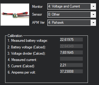
To calibrate current & voltage measurements, follow the APM wiki procedure here: http://copter.ardupilot.com/wiki/common-measuring-battery-voltage-and-current-consumption-with-apm/#calibrating_the_voltage_reading

Start, in Mission planner, with a "Voltage divider (calced)" value around 7,65 as shown in picture:
5. Plugging the Zener+Cap module on Pixhawk servo rail:


The module comes with a three pin standard servo connector. Only the 5V & GND wires are used. You should plug the module as shown on the picture on one of the 6 AUX ports:


Comparison of AirbotPower with other market’s typical power modules:
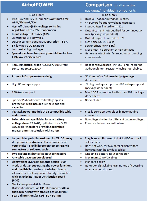


The board is ready for Pre-Orders:

A first small batch of AirbotPower & AirbotPDB boards have been produced mainly for early adopters and first testers.

We need help of the community to produce larger quantities. Your pre-orders will help us know what volume we need to produce and it will help us fund the production per batches. We are in the final stage of finding a reliable production partner (although we can commit on any final planning yet). We expect every batch to take between 1 or 2 months to be produced, so we will work in a rolling planning method: orders will be grouped in “periods”, FIFO (First In, First Out).

To preorder & help funding this project, please simply complete the form on this link:

This form is not an order but a preorder; it will allow me to know what must be produced and you would be billed only later on when boards are made. Please indicate on the form what’s your pack choice and wished ordered quantity. Prices is a worst case scenario defined based on small volumes. If volumes get big enough, I might be able to reduce them:

Pack’s content

Unit price (€ ex. VAT, ex. shipping) *

Unit price (€ incl. VAT, ex. shipping) **

AirbotPower standalone (no cable / no ZenerCap module)

€ 74,59

€ 90.26

Pack AirbotPower+Zener/CAP module+DF13 cable

€ 81,19

€ 98,24

AirbotPower+AirbotPDB+Zener/CAP module+DF13 cable

€ 91,53

€ 110,75

(*) For Intra-European companies with a valid VAT number, no VAT will be charged.

(**) For volumes more than 10 units, please contact me for pricing.

As a final note, here a video of an airbotpower board assembled in a 6S 900mm X4 Airbotservices UAV:

Cheers,

Hugues

Read more…
MR60

Here a typical week-end "dronegeek" DIY build project : expermenting with 3D printing to make a 900mm Pixhawk quadcopter, with 380Kv motors, 16" props and powered by 6S batteries.

Credits for the frame : do not forget this excellent post from Forrest Frantz on light frame construction techniques:

http://diydrones.com/group/arducopterusergroup/forum/topics/building-copters-with-round-tubes-stronger-lighter-easier-to?commentId=705844%3AComment%3A1733743&groupId=705844%3AGroup%3A394475

Cheers,

Hugues

www.airbotservices.com

Read more…