Not quite the $15 billion they spent on Whatsapp last month, but still more than the $1.1 billion they spent on Instagram. The speculation is for grand universes of virtual reality news feeds, virtual reality sharing of private UAV flights, but the reality is probably more down to Earth. It's a play on injecting advertizing into the video feeds that go into the Occulus Rift, with some algorithm that tries to make it relevant to the content of the video feeds. The history of Facebook acquisitions has been pretty disastrous. Instragram went absolutely nowhere.
Occulus VR, like most multi billion dollar startup acquisitions, has never shipped a product. The closest they ever got was a development kit. Now development kit 1 is discontinued & they're still planning a version 2, someday.
The big question when reading about these escalating buyout prices is how much Google is going to pay for 3D Robotics. It'll undoubtedly be the largest robotics buyout ever. Someone actually sat down & made a list of Google's acquisitions.
It's interesting to note that the entire Android universe started out as a $50 million acquisition while the $12 billion Motorola acquisition went down like a lead weight.
To save themselves from looking like the complete idiots they are, Google doesn't normally disclose their buyout prices, but 3D Robotics will probably be sold for $30 billion. Before that can happen, 3D Robotics needs to stop shipping products, of course.
What will Google change about 3D Robotics? Arducopter will be rewritten in Java, require 8 gigs of RAM, 64 gig of flash, & a quad core 2Ghz ARM. There will be mandatory upgrades every 3 days to cripple the offline map functionality & create more annoying, bloated user interfaces that fill 1/2 the screen with search dialogs & frames.
Flights will require loading 1 gigabyte of javascript to your remote control & watching a 5 minute commercial about adsense, which you may click through after 5 seconds, sometimes. FPV video will have banner ads covering 1/2 the screen which may be closed, only to reappear when the wind changes direction. Flights over copyrighted property will result in immediate motor cutoff & incineration of your arducopter.
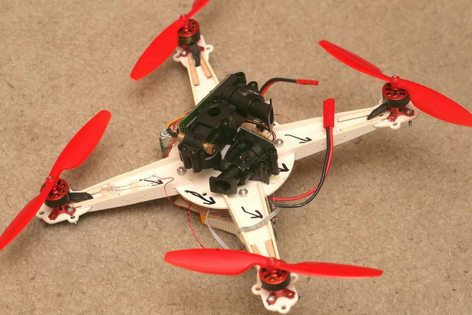
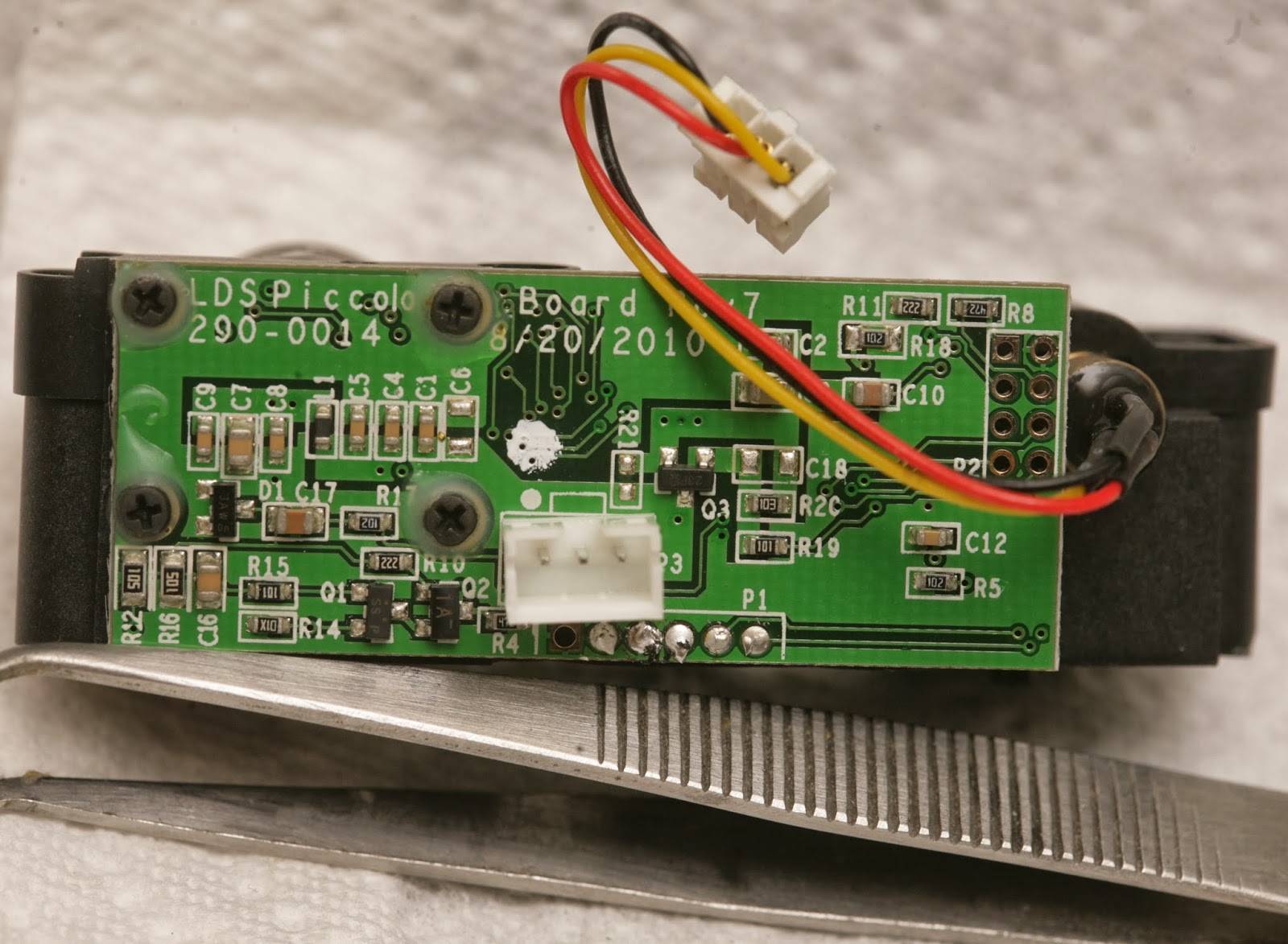
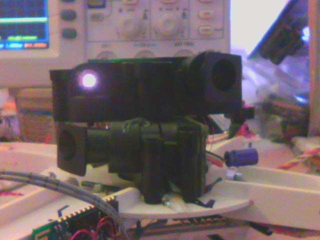
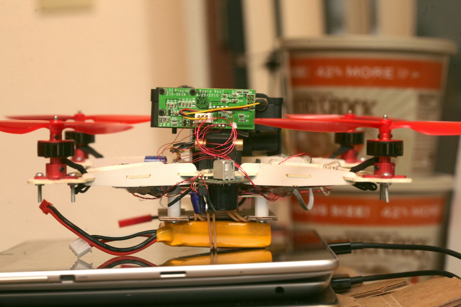
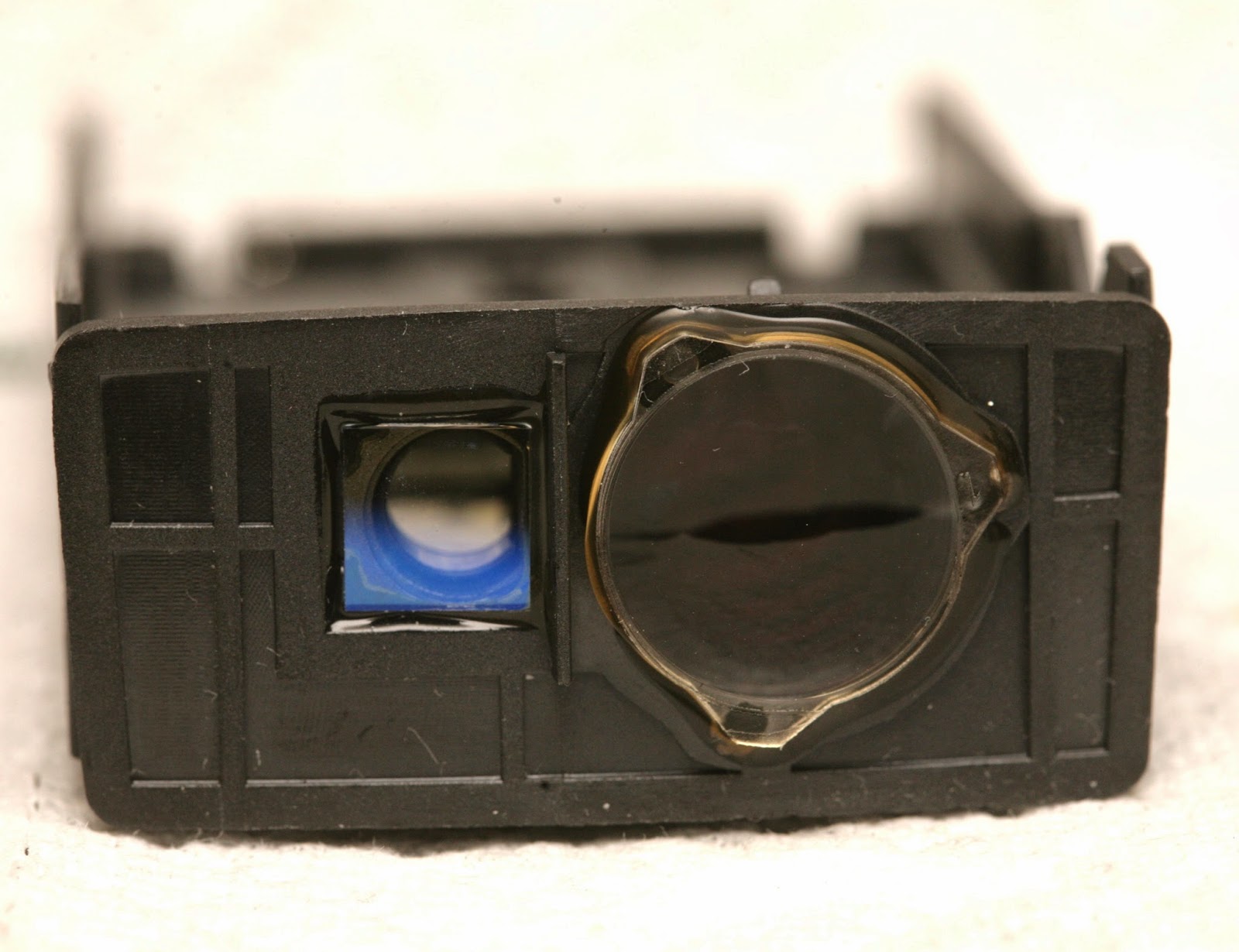
It's definitely a Silicon Valley startup product. There's no emphasis on miniaturization. It's loaded with unnecessary, cosmetic plastic. The PC board is 1/16" thick. It uses 1990's era 0603, 0805 components, full size JST connectors. The laser & camera are giant. It's bare minimum set top box parts repurposed for lidar.
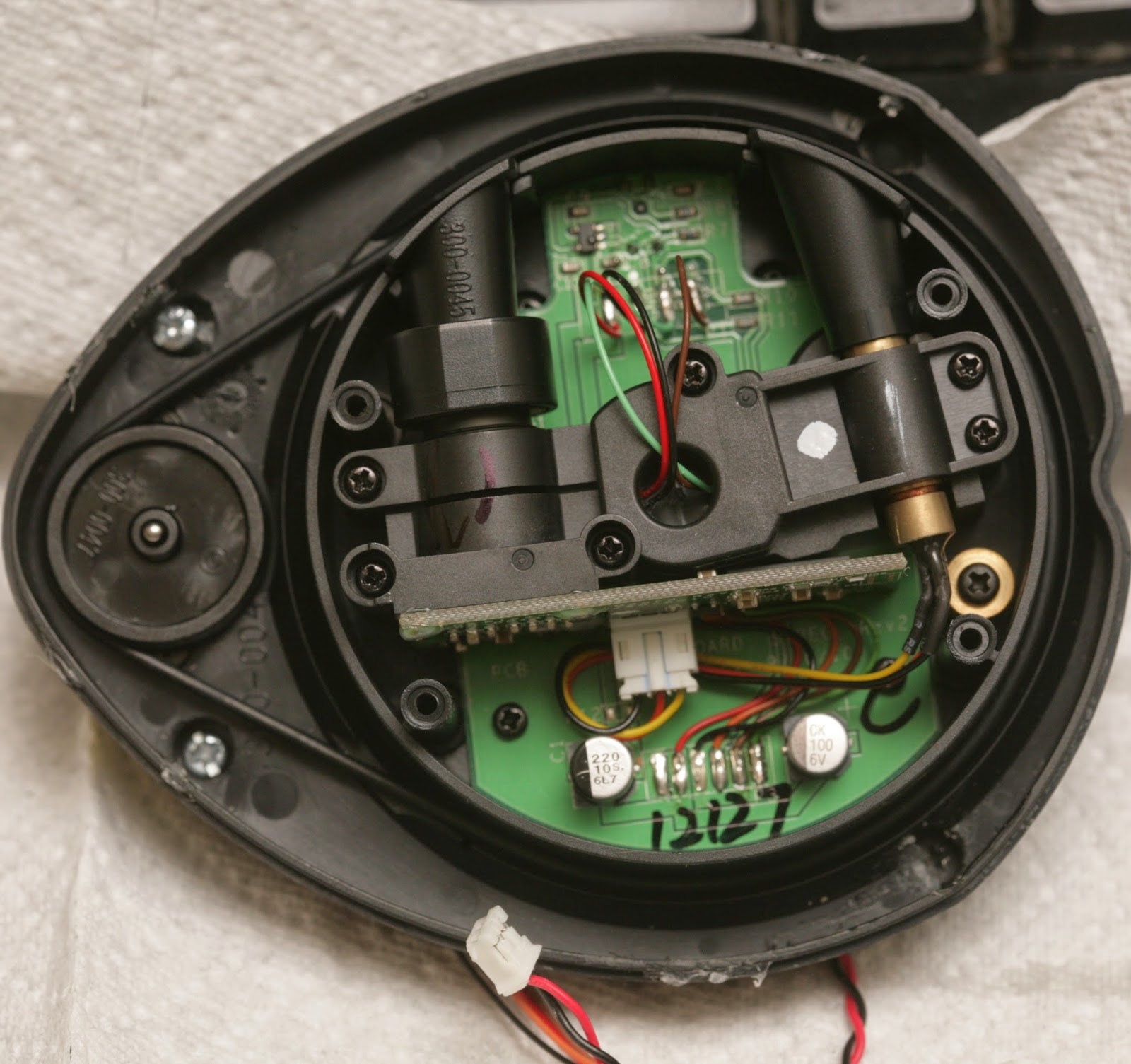
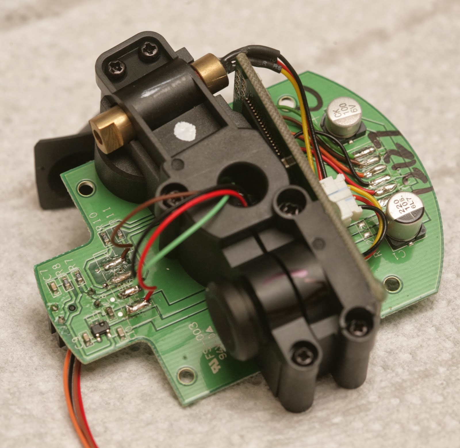
The sensors came from fully assembled vacuum cleaners, since they still had the screws with threadlock.
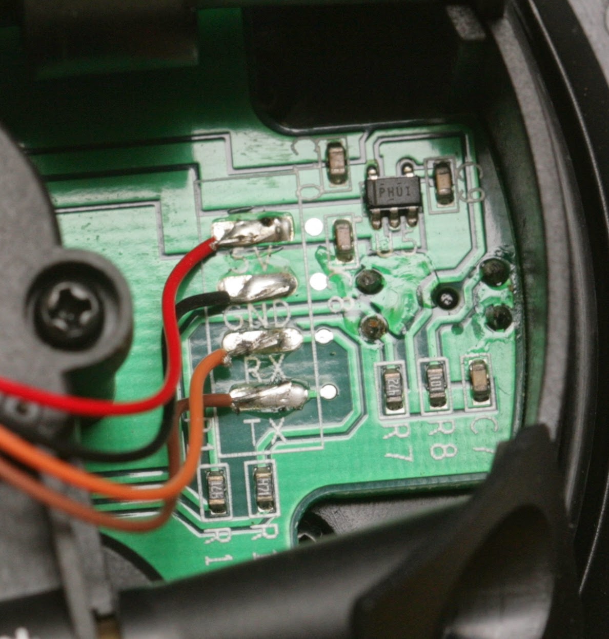
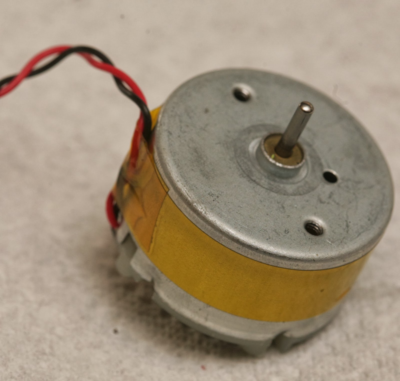
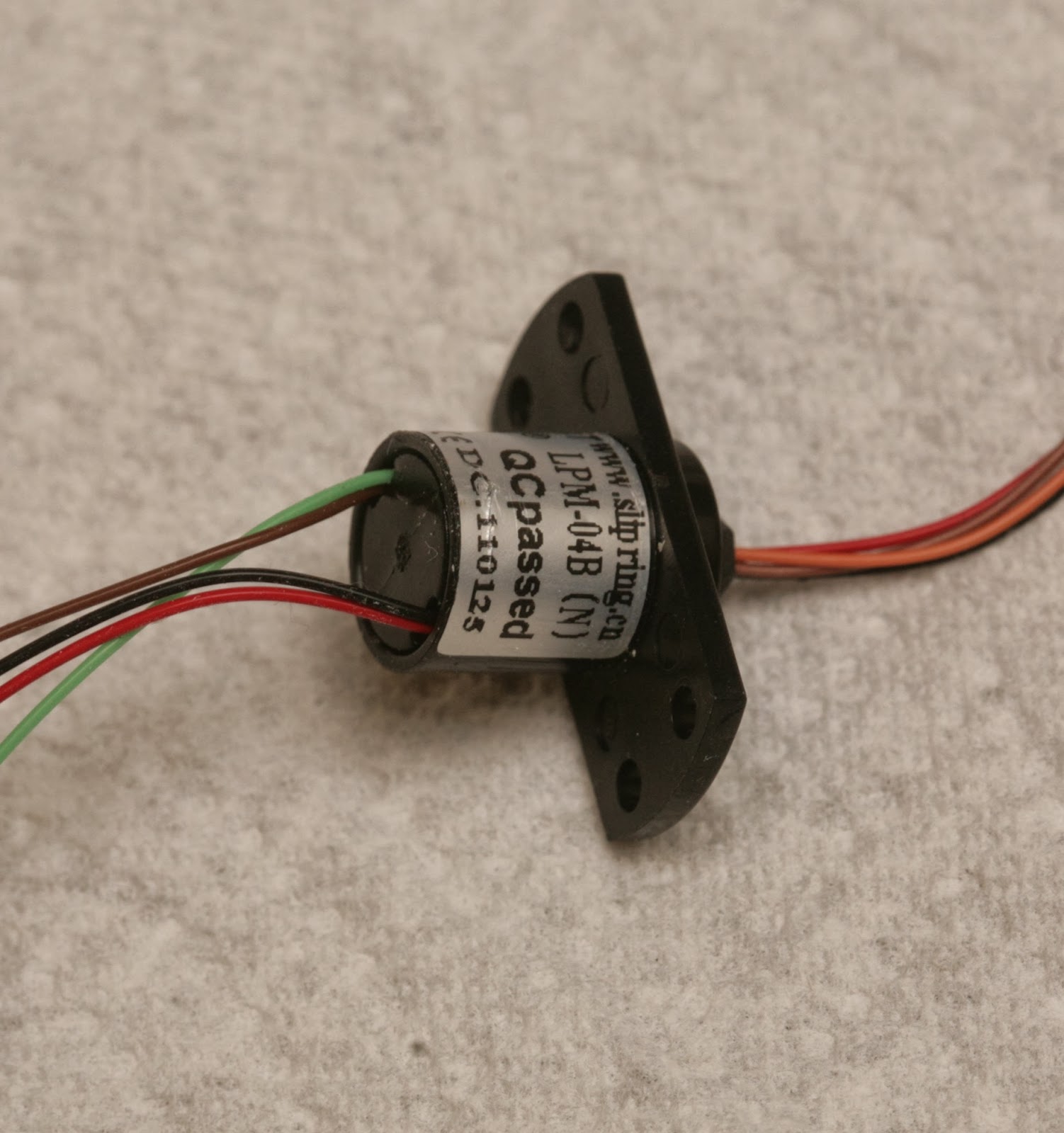
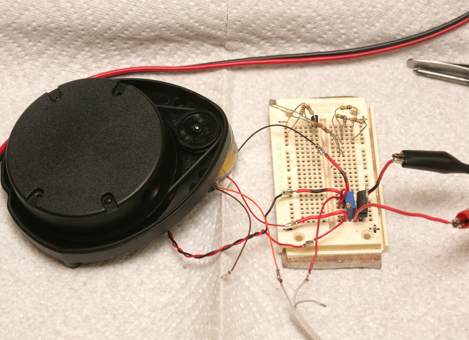
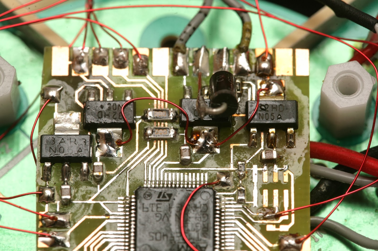
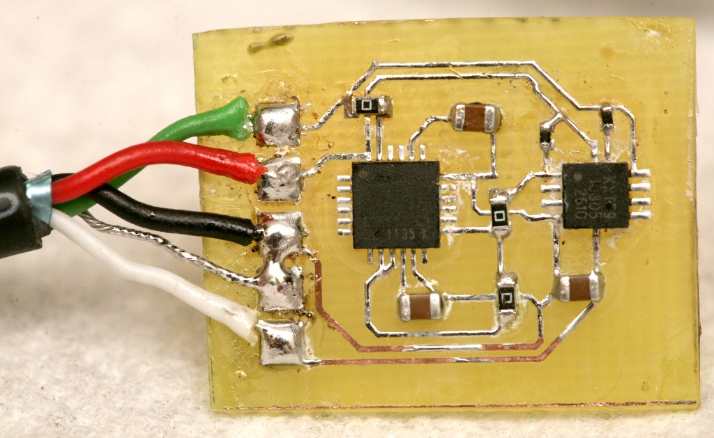
Since it clearly was too heavy to fly in its spinning form, it was time to extract the bare ranging element. The ranging element weighs 30g. The PX4flow weighed 17.5g. The board has 5V labeled, but it's converted to 3.3V by an LDO.
red: 3.3V black: GND orange: photodiode output 3.3V when interrupted 0V when clear
brown: TX data going into device green: RX data going out of device
In true silicon valley H1B worker fashion, the TX & RX labels were reversed. TX on a device normally means signal going out of the device, but the sensor has it meaning signal going into the device.
A 220uF cap filters the 5V power. A 100uF cap filters the 3.3V power. The UART signals have 4.7k resistors.
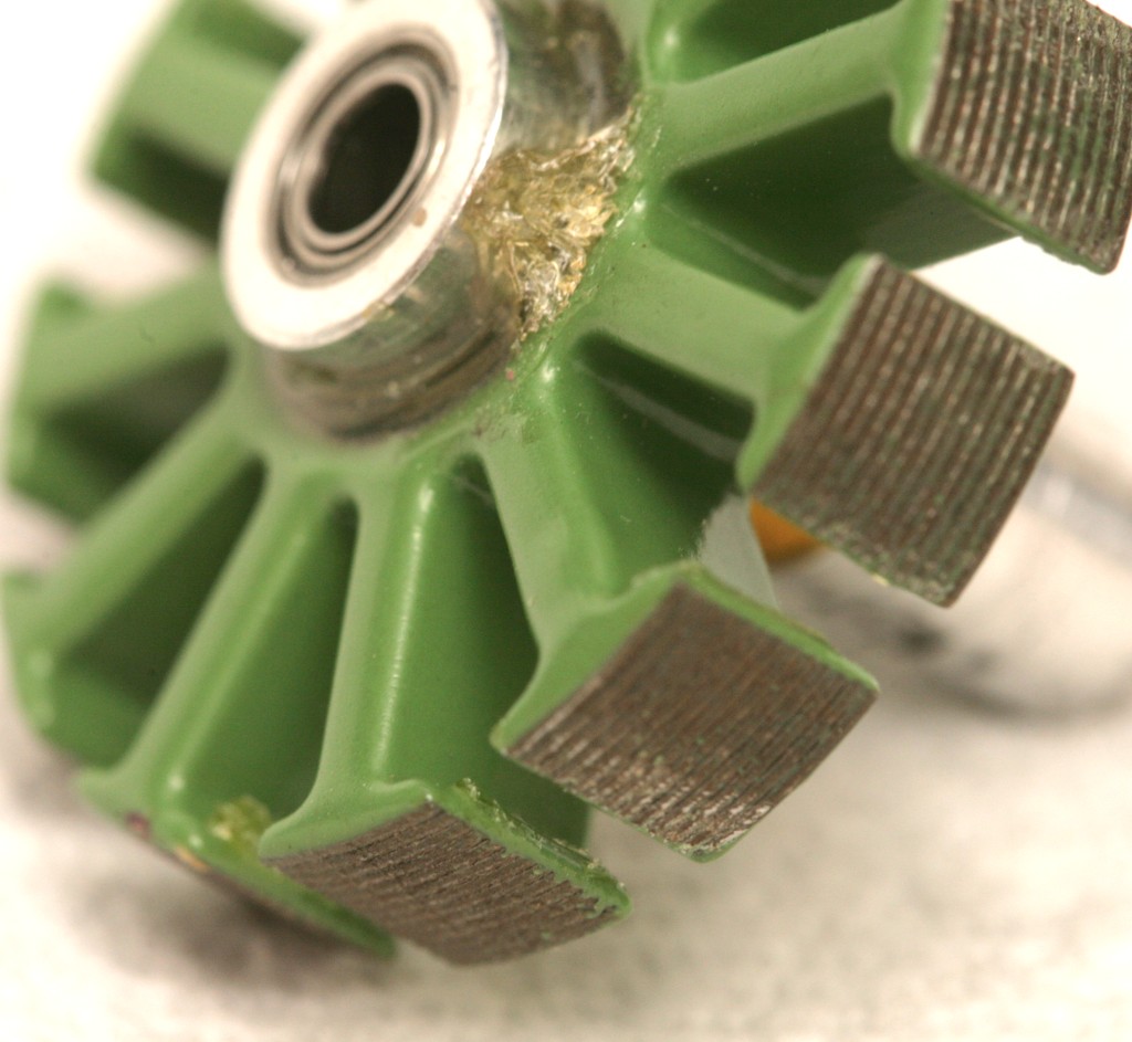
The photo interrupter pattern has 15 interruptions per revolution with a shorter one to tell it where the azimuth is.
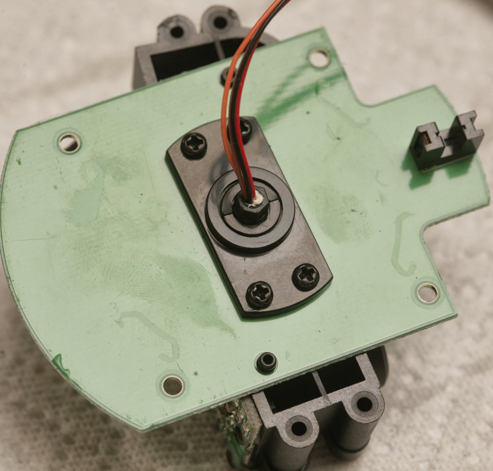
There's a decent quality bearing & brushed motor.
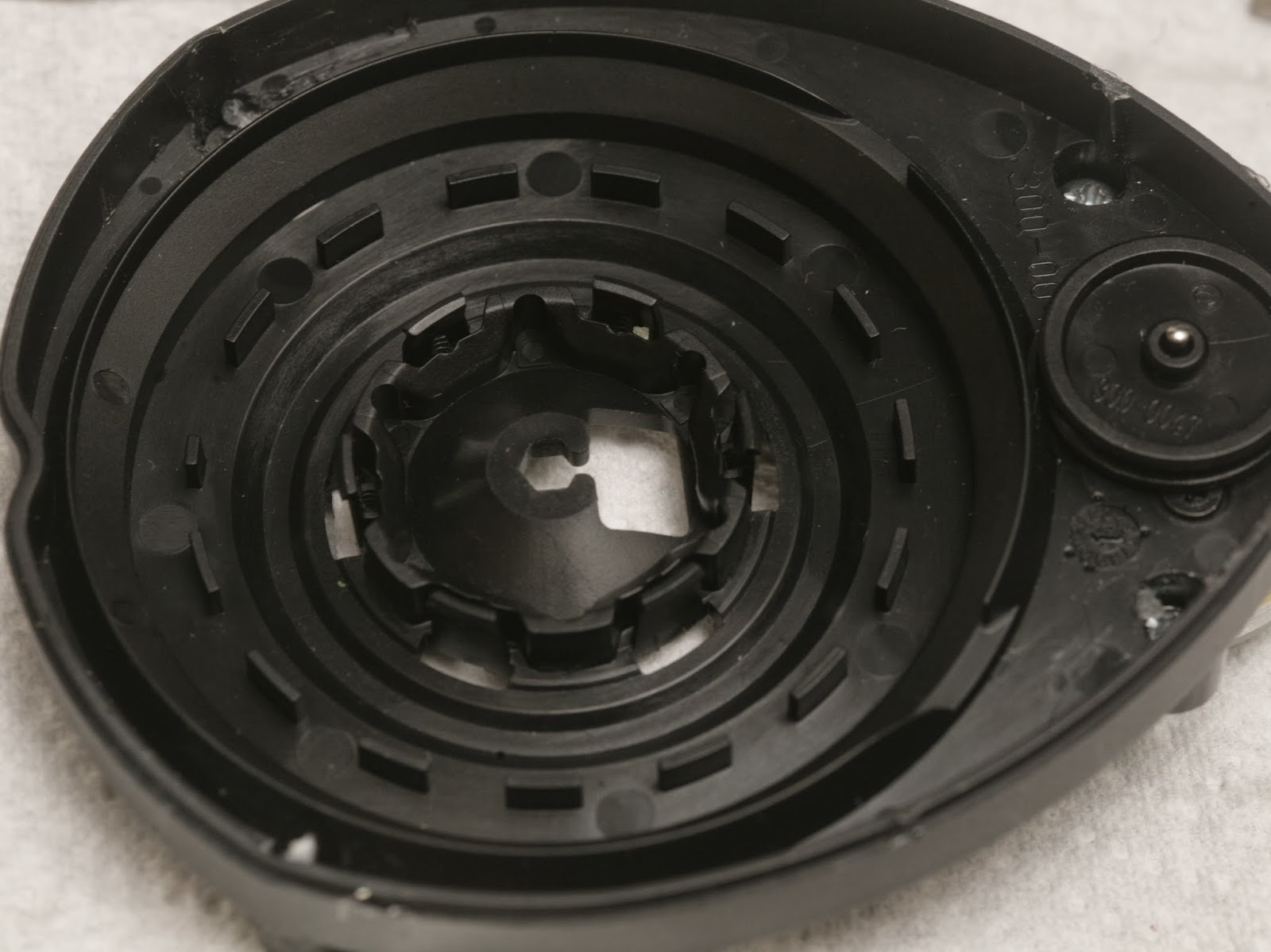
The slip ring would be very useful if you're into synthetic aperture radar & have a way to drill perfectly aligned holes.
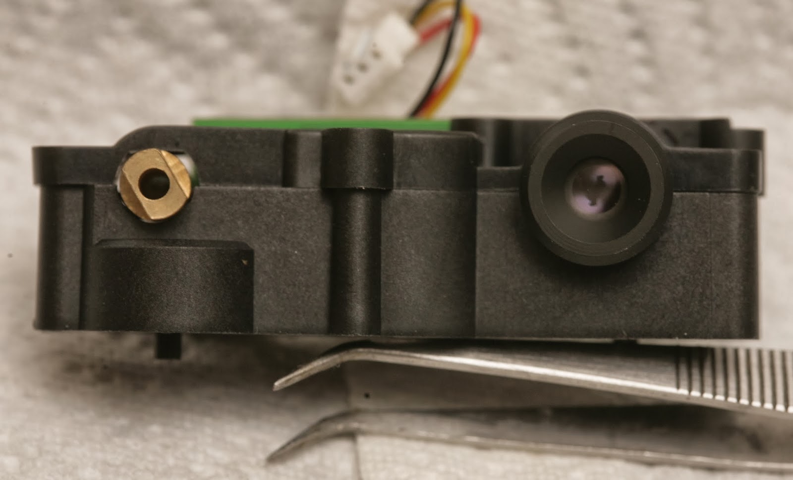
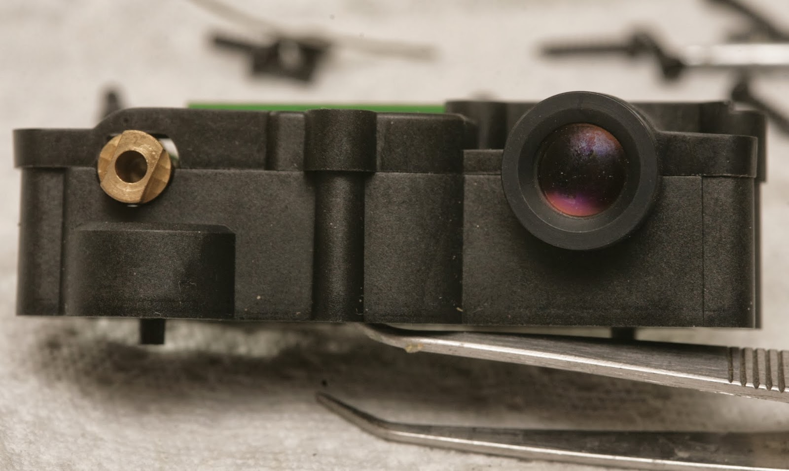
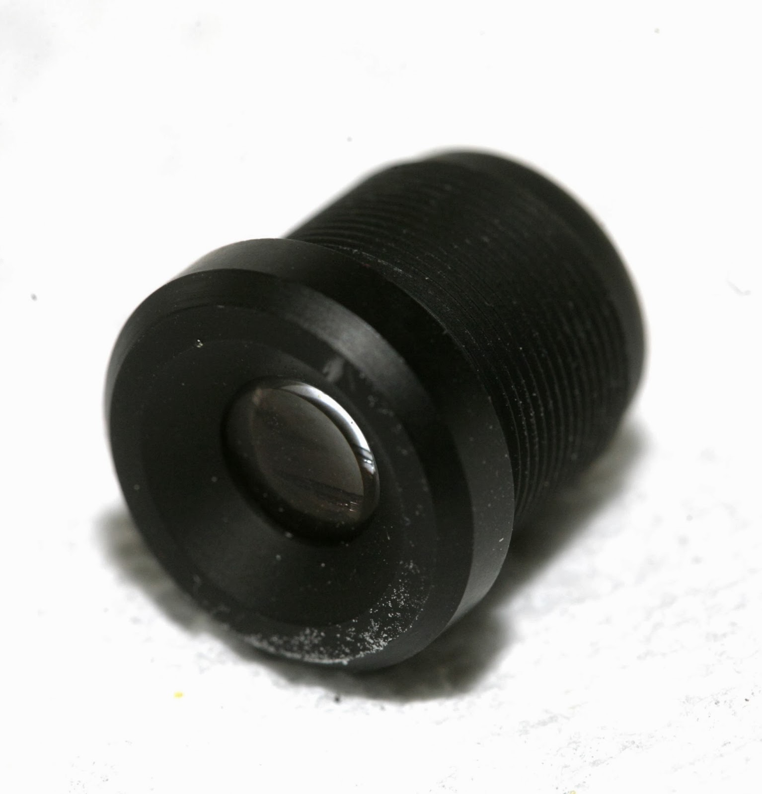
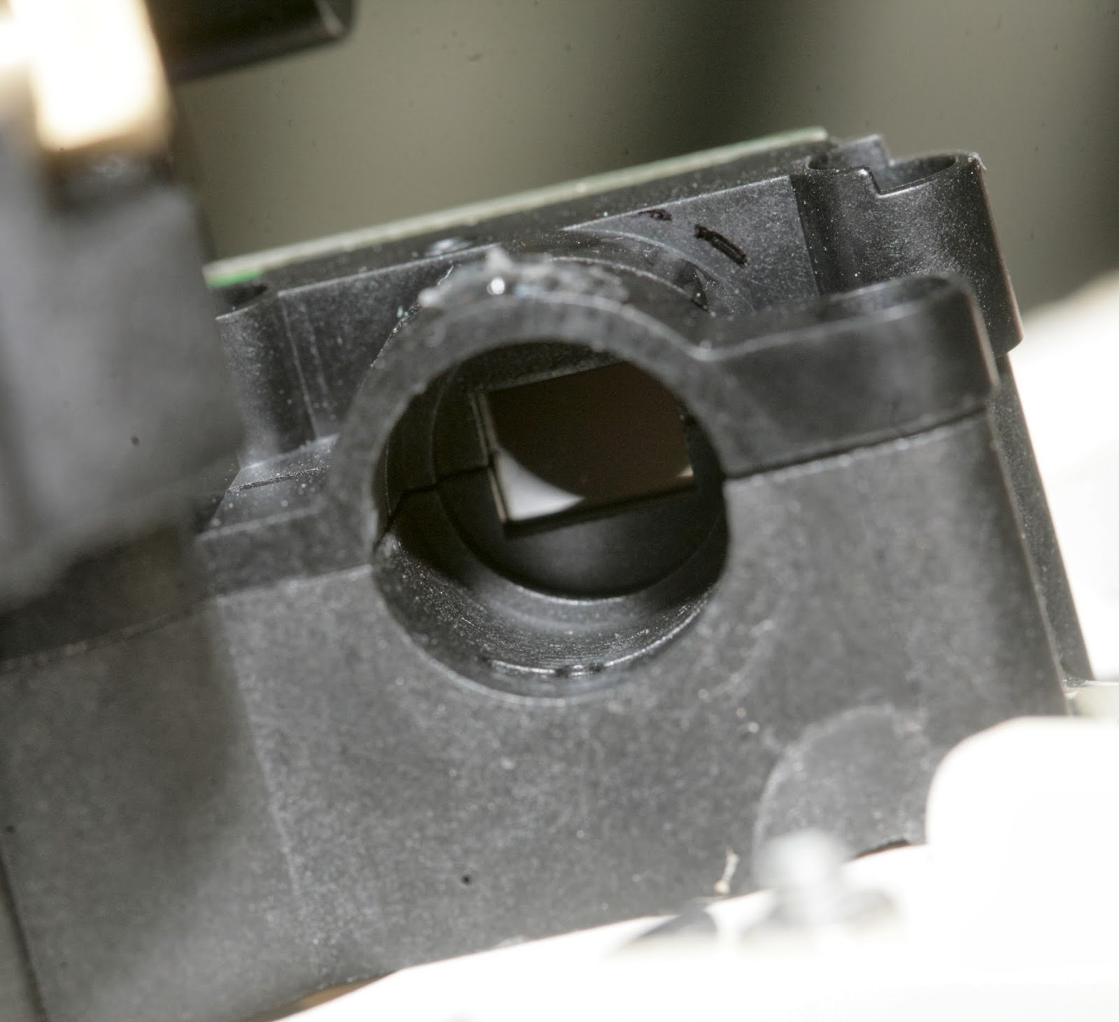
The lens is variable focus with 1 screw clamping it down. Once unscrewed, it becomes lose. There's no way to focus it without an unknown debugging mode.
2 of the modules had smaller lenses. 1 had a larger lens.
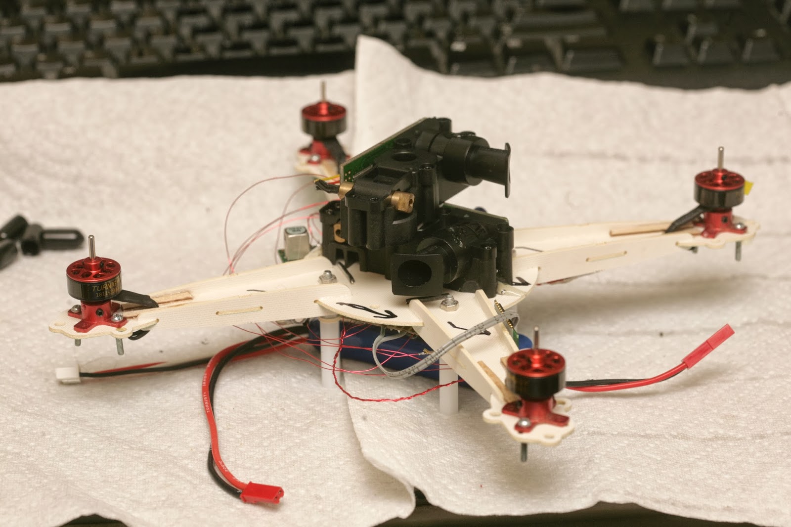
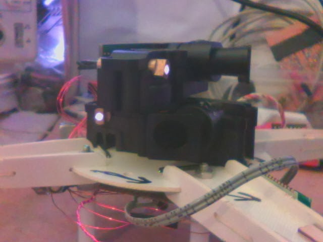
A 1st attempt at attaching everything led to a huge brick. It's going to be really slow. There's no durable way to attach the 2 LIDAR modules.
After a day of getting only error codes from the XV-11, the problem narrowed down to the rotation sensor. Then it became clear that it needed a very very specific signal from its rotation sensor.
Lacking any meanings for the error codes, the key was reading the rotation rate encoded in the packets. The internet claimed a very narrow range of 180-360 rpm being required. There was no way it could do more than 6 scans per second.
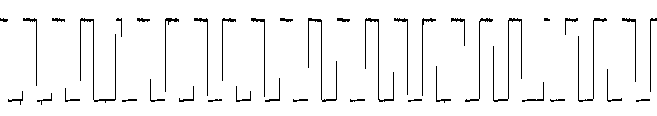
Even with a stock sensor that still spins, with the RPM perfectly dialed in, most of the readings were error codes. The stock motor needed to be down to 2.8V before it was slow enough. Then, there was routing the stock rotation sensor through the TX pin to capture it.
That revealed the exact direction of rotation & azimuth code, 14 pulses of 50% duty cycle & 1 pulse of 25% duty cycle. The 25% pulse needs to come after a 75% delay. It doesn't work if the pulse comes before the 75% delay. There definitely wasn't any margin in the software for any anomalies.
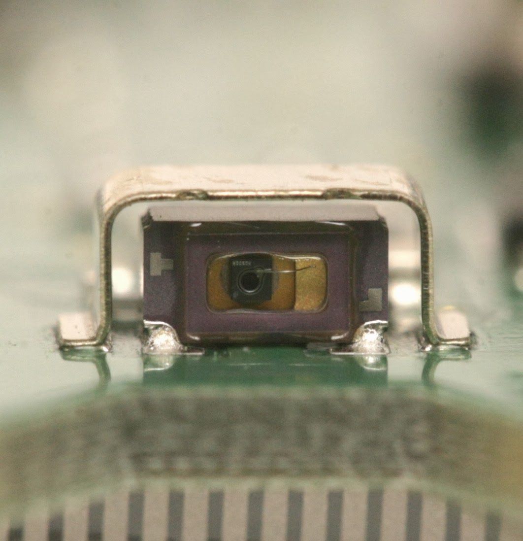
A crusty webcam reveals the IR laser. It would be bad to look at it. It's actually correlated to the rotation speed. It doesn't turn on if there's no rotation. It's very faint if the RPM is too high or too low. It's only fully on inside the narrow RPM range.
So hacking it to stay on with no rotation & using it as a horizontal range finder is a dangerous application of something that's safe in its normal application. You definitely need laser goggles.
RPM out of range
RPM in range
1 of the sensors failed. Tried focusing it, but it wouldn't detect farther than 1m.
It doesn't have any focusing threads. It just slides in & out.
Tried bridging all the 3.3V regulators to cool off the board. It was melting off the standoffs from only 0.2A.
After a full day of replacing the sensor, the complete stack briefly flew manually. It took nearly full power. IMU drift was too high to fly more than a minute. 2 PWM pins were swapped.
The only way for the coordinates to work was to assume it was always pointing north. The calibration has to face the direction it's going to point when flying. Rotating the lidar output to point in any arbitrary direction caused massive glitches, every time it slightly rotated.
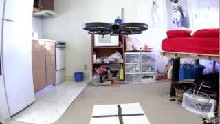
The video has several attempts to hover, several attempts at a waypoint mission. The waypoints failed because of an unknown software bug. The final flight was an attempt to hover, with the PID gains converging in on decent values. The testing ended when an arm broke, despite all the double layer wood.
Altimeter was all over the place. Seemed to be power distribution interfering with the cable routing or having the mane board under the frame.
Flight time was 2 minutes & maneuvering was real lousy. It definitely moved like a single female, very overweight & unwieldy.
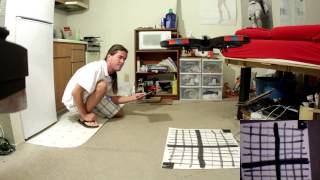
It had to stay far from the walls to prevent crosstalk, yet be close enough to prevent detecting the floor. Didn't have any obvious floor detection at 1.5m from the walls & 0.3m altitude.
Velocity needed to be updated at 10Hz to have any success.
Absolute position was excellent. There was no more drifting.
Would recommend wearing laser goggles.
IMU drift made it drift. Would need to start over on the vibration problem, with the new board arrangement.
This was an interesting concept for indoor navigation. It's 1 of those ideas you're always aware of but dismiss because the electromagnets would be too weak. Someone actually tried it.
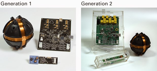
Magnetometers have gotten sensitive enough for it to work. Barely visible in the photo are 3 large inductors used by the roaming unit to sense very faint electromagnetic oscillation from the base station. The base has lots of capacitors for pulsing the coils with a very high current.
The roamer measures direction & intensity, but probably not time of flight. The intensity measurement is probably very bad. The 1mm precision they claim would be in tangential movement. 2 base stations could give it much better accuracy, but require alignment.
Increasing the range could be a matter of bigger inductors or a bigger base station. There are no teardowns or benchmarks. The consumers are all salesmen or reporters with no interest in how it works. There's no data on its precision at its maximum range of 8ft.
The advantages would be no calibration or alignment of cameras & no interference from ambient light. You could throw the base station down anywhere. In an explosion of lots of micro startups with lame ideas & no funding, this idea seems to have potential.
They remind me of Invensense, initially targeting the news maker of the time: 3D printing, & conspicuously avoiding any mention of the giant elephant in the room: drones. Invensense still targets phone cameras, making no mention of the millions of flying toys on their page.
For better or worse, we got ourselves a dot com boom. Unlike the 1st go round which affected everyone, it's all concentrated in 2 companies this time, they're a lot harder to get into, but that concentrated wealth is letting the lucky few do much bigger things.
It's going to be a hell of a flying space for developing indoor navigation algorithms, developing very efficient vehicles with wing loadings too low to fly outside, not having to wait for good weather. Imagine the Vicon system it's going to take to provide optical navigation data to the entire space. The Vicon system alone could be worth a few billion 3D Robotics's.
Google & Facebook are buying most everything with a roof, to perfect most everything from robots to cooking, to the fabled dot com foosball tables. With a lot more of the flying being done by the big companies, a lot more of a career that was once the domain of everyone is requiring master's degrees.
It's another sign of the UAV business following personal computers, internet service providers, Linux, & 3D printing. Micro startups have just enough capital to produce the starting point, but the true penetration of the technology ends up being dominated by the big companies with the capital to push through massive infrastructure & massive investment that it takes to bring the new technology to the masses.
The only way to survive is to get bought out or to go back to school.
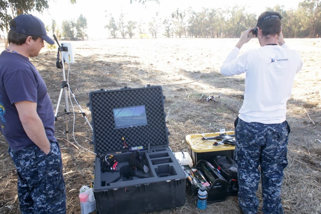
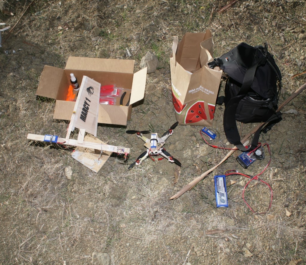
A complete home entertainment system for FPV, but with the same old analog NTSC video.
For someone who reads rcgroups.com & diydrones.com, there was very little new to see, besides the real life equivalent of the photos.
Thought that was very Silicon Valley: a stock reference board for a standard set-top box with the standard server room BNC, RCA, RJ-45, connectors untouched, all to send very delayed video over LTE.
The most hated vehicle there. It was really wobbly.
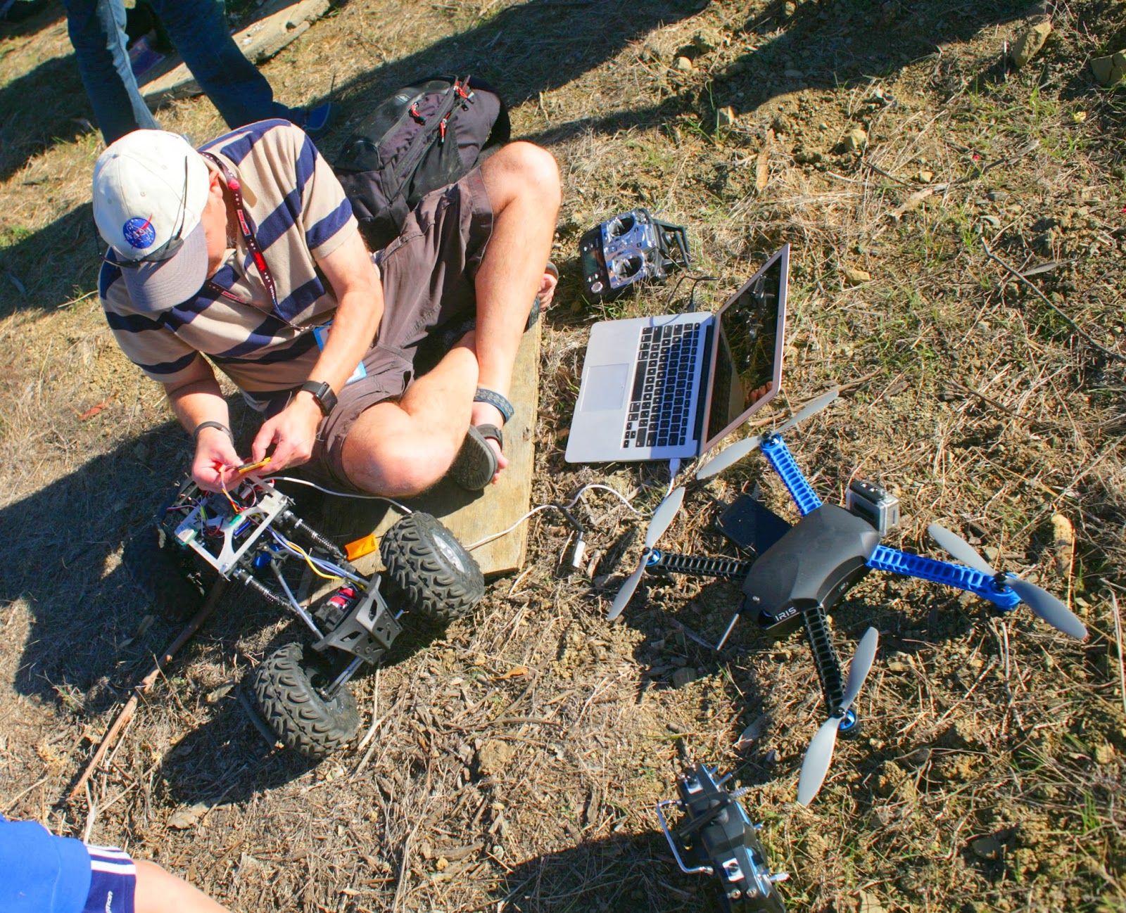
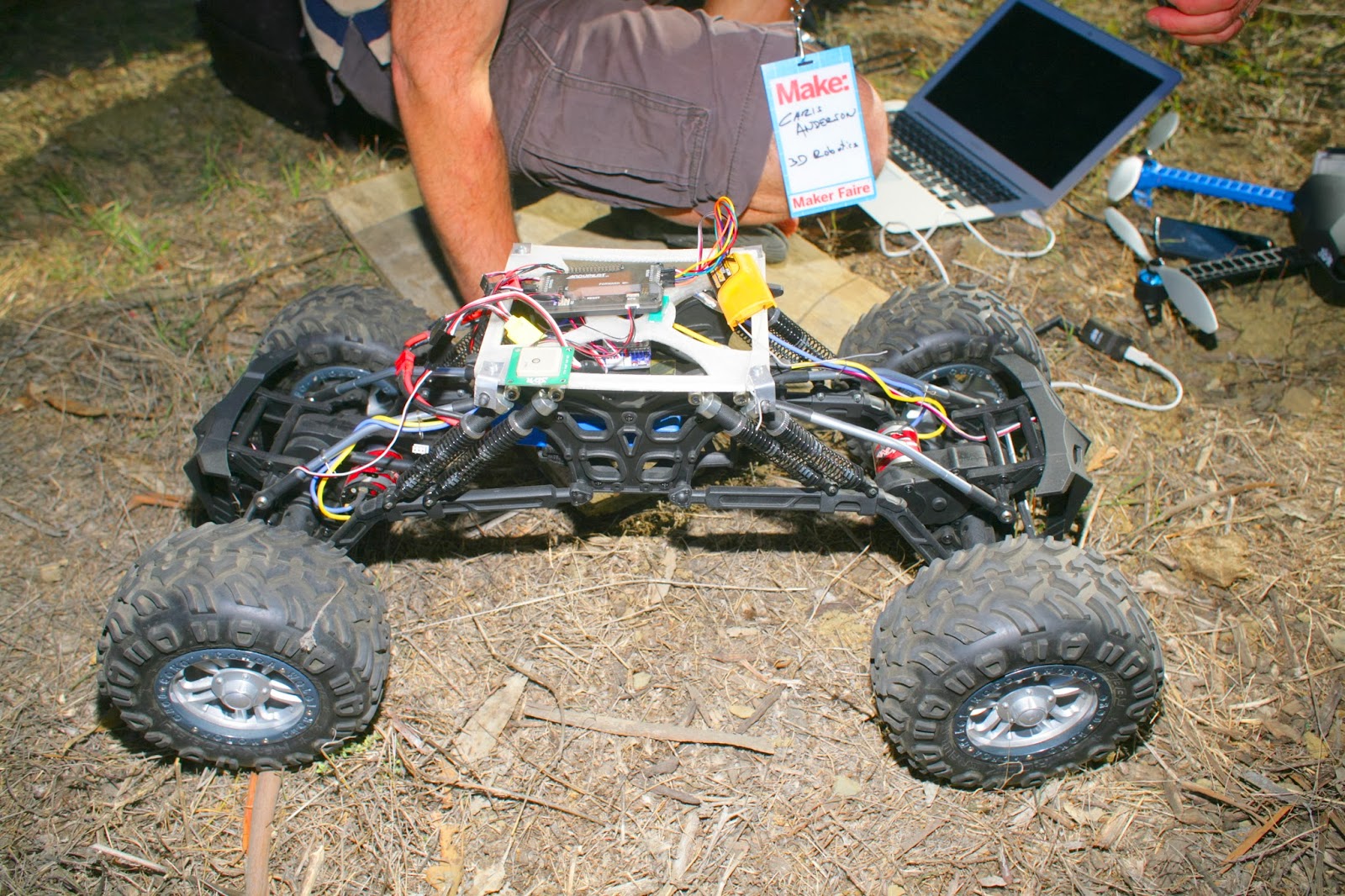
Some guy trying to get a rover to work. Unfortunately, it only rolled a few feet, very slowly.
A chassis that would normally cost $200 on hobbyking was $20 at a garage sale. Could desperately use something like that.
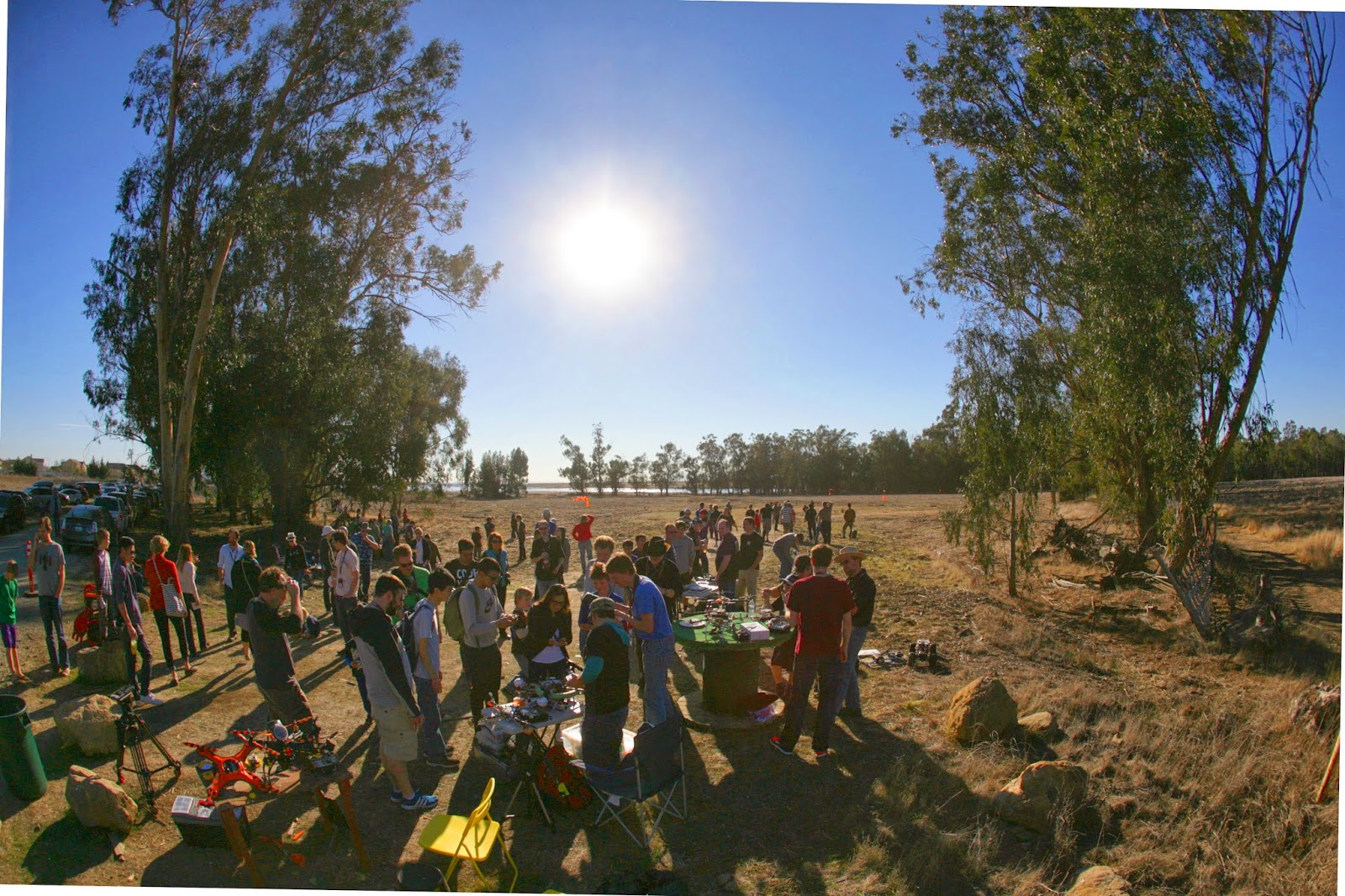
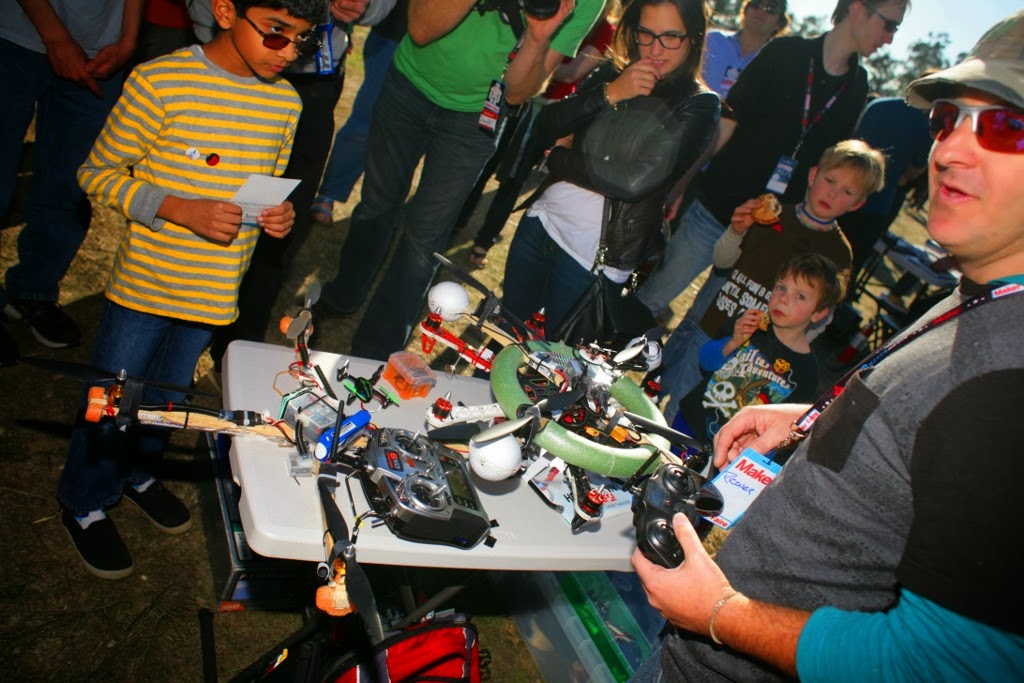
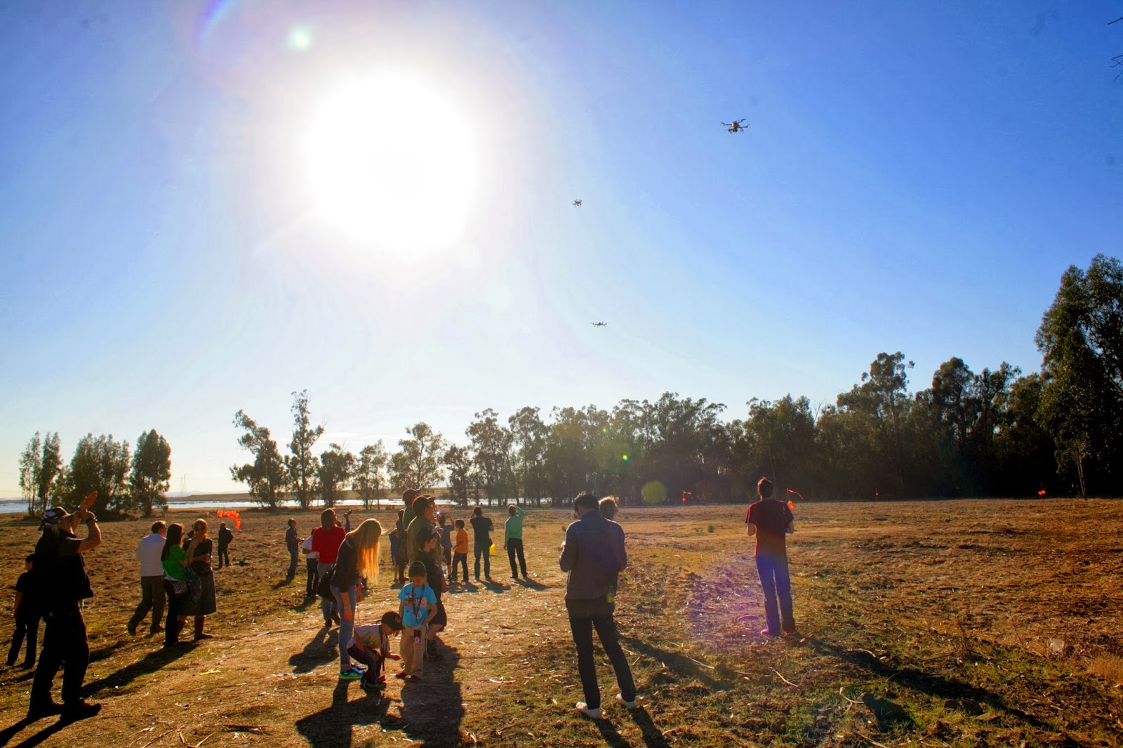
Everyone congregated on a south field, while a north field shown in previous videos was empty.
Standard quad copters.
Some ghetto indoor vehicles. Marcy 2 was a complete disaster, as a vibration problem, wind, & uneven ground screwed up her indoor navigation sensors.
3D Robotics dominated the attendance.
There was very little autonomous flying, only a few times someone would go into loiter mode or a lost radio link would send a DJI Phantom into the trees because some arcane loss of signal setting wasn't set right. No-one replicated any Marco Robustini demos.
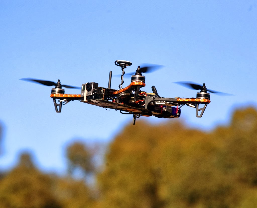
The stock 3D Robotics Iris hovering far from the trees looked like it wasn't going anywhere, but it did look twitchy. 1 DJI guided black sheep was hovering motionless near the trees. It drifted a long way, as it tightly tracked the drift of GPS near the trees. Still looks like perfect calibration, perfect prop balancing, perfect vibration damping, & satellite visibility is a big part of the results.
Despite the improvements in sensors & software making autonomous flying much more accessible than years ago, there was little interest in it. After all the expense & calibration, people would rather fly manually than program a route & watch it play back. There was certainly no interest in making a timelapse movie from 1 place in the sky.
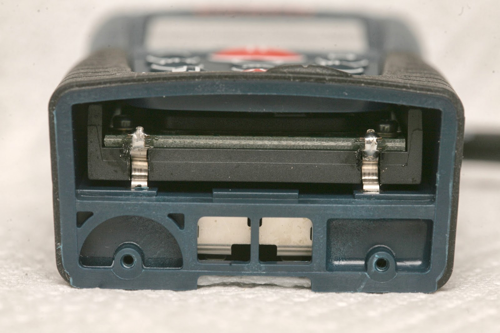
Everyone wants to hack a laser tape measure for aircraft navigation. It would indeed make a cheap, extremely accurate, reliable altimeter.
Today, it's the DLR130. It outputs at 1cm accuracy at 3Hz. You need 10Hz for flight, so maybe there's a way to speed it up.
It's very well constructed.
The battery contacts must be desoldered.
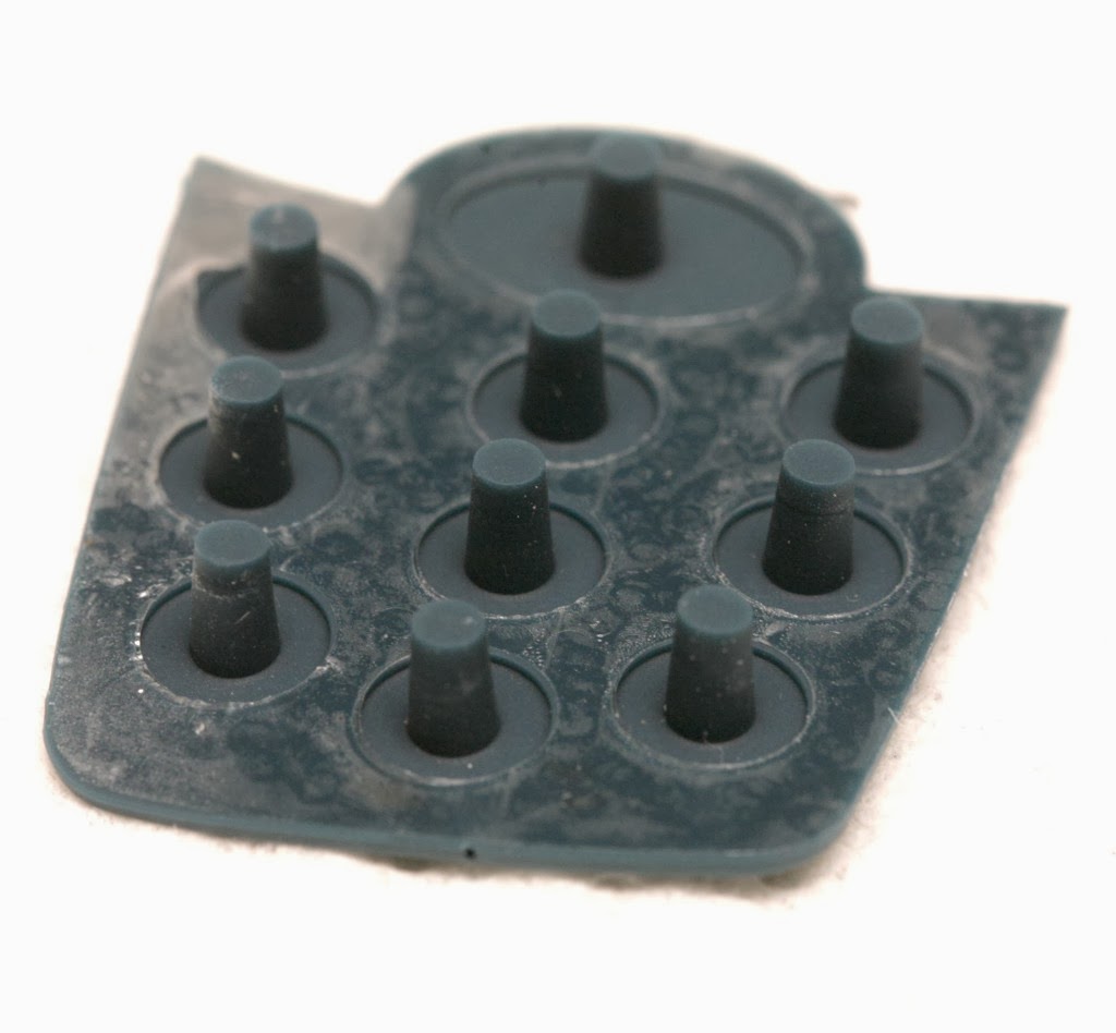
The keypad must be removed.
A 100uF 16V cap didn't survive the operation. It got hung up on a protrusion on the battery side. The optics & keypad are integrated in the same frame. It's much lighter than the complete package.
The LCD could be removed to make it lighter, but never reattached.
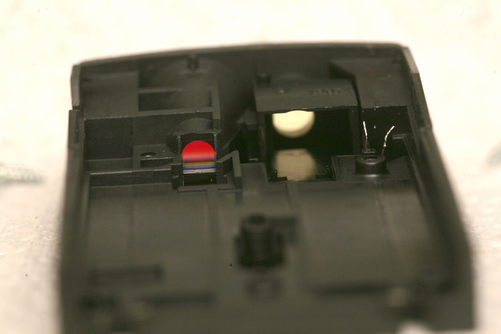
A solenoid shutters the laser every few seconds, for some kind of calibration.
The LCD is held on by double sided tape which must be carefully pried without shattering the LCD.
The emitter & receiver have different filters.
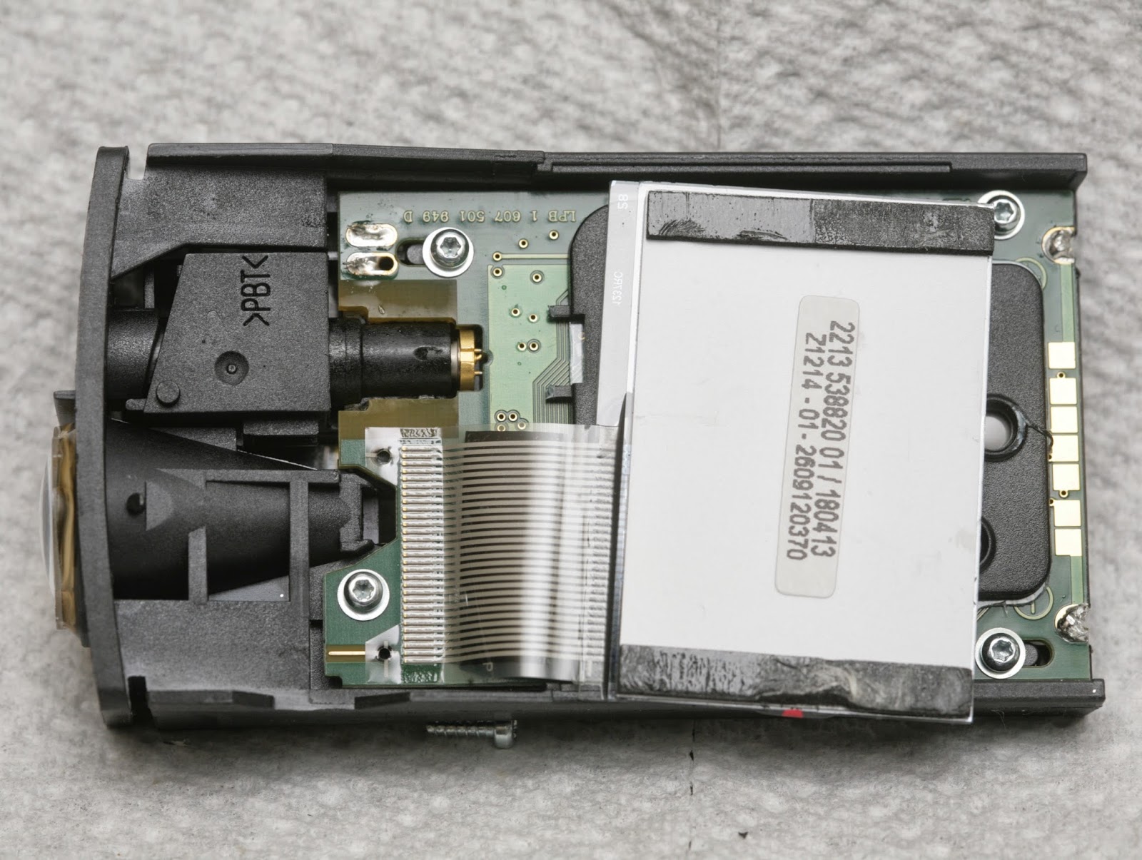
The laser used for aiming it also seems to be the laser used for ranging. The keypad & processing board occupy the same space, so it couldn't be stripped down any further.
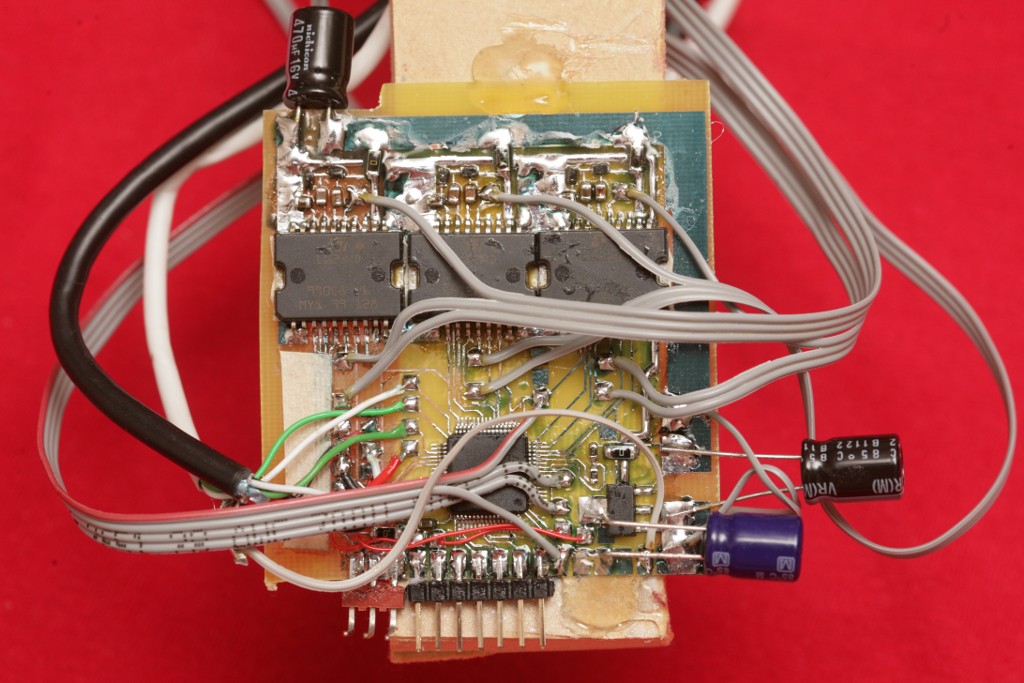
The magic is done by the CF325. The internet got nowhere with it. There's obviously a very simple measurement result going to the ATMega169. The entire left half of the circuit board could probably be omitted, but the update rate is probably limited by the CF325 instead of anything programmable.
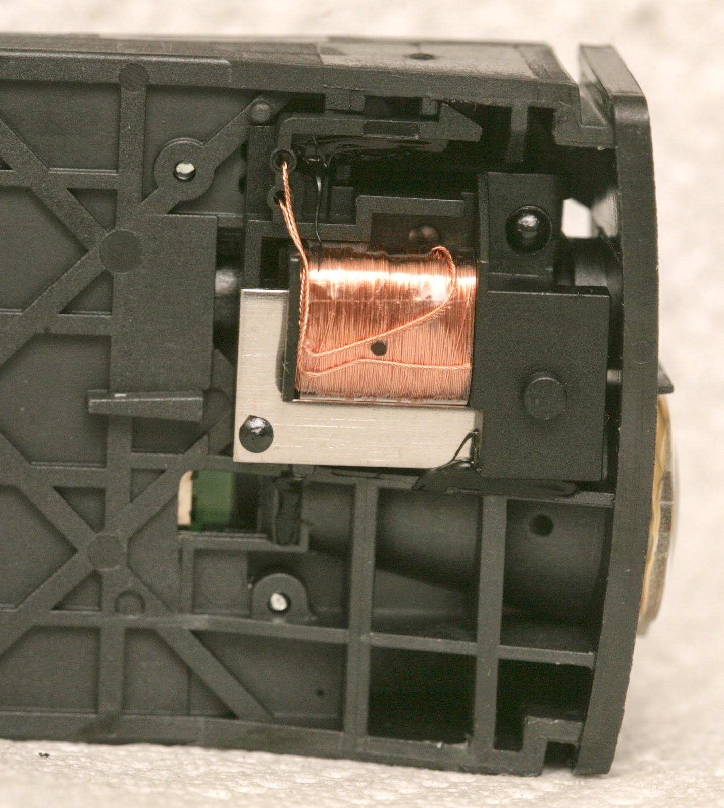
The reflected light goes into this magic device. Years ago, this used to be a giant tin can. Years before that, this was a 1lb device.
It's not necessarily quad copter, but tractor based. Did not know Calif*'s mane crop was lettuce or that it produced any vegetables at all, since there hasn't been any rain since 2012. Though quad copters harvesting lettuce is a highly dubious proposition, there's certainly money to be made from tractors.
That guy was rich. Listening to him complain about the lack of PhD's to design computer vision algorithms, you thought just stop being a dick & hire people who know how to design computer vision algorithms instead of insisting they have a PhD from Berkeley. Most of the discovering, inventing, engineering, living & dying in this town is done by makers & hackers working in garages. Yet another overstuffed taco salad supported by the federal reserve.
Your other thought was agriculture might actually become a big business as our generation believed 20 years ago. Unlike what we believed, the money is not going to biologists who study genetics, but to designers of robots & businessmen.
There are no jobs for biology majors who learned about robotics on their own, only for engineers who learned about biology on their own or businessmen who can track down farmers with bucks.
It's probably a supply & demand issue. Few people can pull off the engineering side & business side while everyone can do the biology part.
A huge aversion has emerged to the genetic engineering we thought would comprise most of the expansion in food supply. A lot of that is lack of knowledge about genetic engineering & movies, but whatever. For now, you can't use genetic engineering to feed Africa. That leaves using automation to expand the biological system we already have.
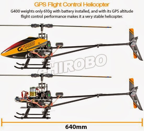
Clicking through some ads reveals there's now a flood of banging good GPS autopilots out there, being marketed towards RC pilots. They're a lot more stable than anything I could afford, owing to the latest GPS module, barometers, & the arducopter source code, which they all undoubtedly copy.
Gone are the days when someone would tear them open & study the part numbers. The new customers are RC pilots with no idea what's inside. It wouldn't be surprising to find uBlox-7 & MS5611 in all of them.
Even the mighty Horizon Hobby finally caved in & started selling a GPS autopilot, though marketing it exclusively as a return to home feature.
The trick with autopilots is once you have one, now what? They're good at making timelapse movies. They can fly to places that were impossible for a human to reach manually, but the newest FPV systems make those places accessible for a human.
They're supposed to be good at returning to home when contact is lost, but there's very little evidence of that being used. It's still a lot of trouble to wait for GPS to lock on, make sure everything is calibrated correctly, just for that 1 feature.
There was some energy behind the following camera concept, but they probably weren't accurate enough to do a good job. Now there's hope for massive agricultural demand.
Autopilot for an RC pilot can get pretty boring, once the novelty of seeing it hover wears off. Hobbyists who design robot algorithms still seem to be the mane customers.
It was suprising that the mane media avenues: tested, flite test, rcmodelreviews were completely devoid of the GPS autopilot boom, emphasizing indoor quads instead. Even the mighty black sheep became famous not because of an autopilot but manual control.
In the beginning, there was spyplanes.com. Then there was 3drobotics.com. What a surprise when my recuiter spam feed came up with another one in San Francisco called Airware. They showed a location in Newport Beach, but like so many others, probably had to expand North to save on real estate costs & be closer to the cloud/dot com boom.
It's yet another agriculture quad copter play. Besides tacitly luring photography hobbyists by branding the quad copter as a professional product for agriculture, there's no logic behind all these startups pitching quad copters for agriculture. They can't efficiently image thousands of acres. Sensefly probably had the best model with flying wings, but not the money or the resources to build up a community movement.
Despite not getting any interest, I did manage to get the recruiter to return a phone call, a huge breakthrough. The UAV business has just exploded to the point of not being the domain of makers & self starters anymore. They just want formal masters degrees.
Did the maker movement make the engineering degree mandatory?
In the old days, there was a novelty to someone picking up electronics on his own. It showed the ability to learn without being told what to do & the ability to be motivated without the threat of failing a class. While there were always places like Lockheed which would never touch someone without a formal engineering degree, it was not uncommon to get in elsewhere with a biology degree & a lot of design experience.
Nowadays, with the maker movement & the rise of the goo tube hacker, that doesn't work anymore. Everybody knows how to design a robot. It may be that they're now getting inundated with self taught engineers to the point that the degree is now the rarity.
It is horribly impractical, but works with enough glue.
No idea what motivated this, but once you get obsessed with a communication problem, nothing can stop you. It might be the hope of getting very long range or the desire of unemployed programmers to remember they can still write programs.
Wifi isn't really wireless because the range is useless. The phone company is worthless because it's extremely expensive. Everyone dreams of running PPP on a private, long range serial port radio that can reach for miles.
A serial port radio like the XBee, 3DRRadio, or CC1101 can potentially give real wireless range, but has issues. IP requires full duplex asynchronous communication. Hook up your PPP connection directly to a 3DRRadio & it won't go anywhere. Without constant rebroadcasting & just relying on TDM for full duplex, it goes nowhere. The packet loss is too high & TDM gets completely jammed.
The best results from serial port radios have come from filling the entire bandwidth at the highest bitrate with repeated packets & hoping some data makes it through. The fastest full duplex has come from constantly broadcasting beacons & waiting for replies, regardless of data usage. To improve matters, the download packet size is 5x bigger than the upload packet size.
It's not an efficient algorithm & it doesn't reach the theoretical maximum bandwidth, but it's practical. The algorithm would ideally be on the radio module instead of the host computer, but having it on the host allows the radio modules to be interchanged.
The idea is to have a sliding window of packets constantly rebroadcasting until they all get ACKs. Ideally, the error checking is done on the radio module, so the entire packet doesn't need to be sent over the serial port before sending an ACK.
The bandwidth is too low to have the ideal header. A 1 byte sequence number needs to make due instead of the 4 byte sequence number in TCP. Having only 1 byte for the sequence number makes it ugly. A single error will throw off the sequence numbers & lock it up. The windowing algorithm is horrible & kludgy, but works.
The CRC checking on the stock 3DRRadio firmware was not effective. Even with forward error correction, a lot of errors got through. So you had to wait for the entire packet to transfer over the serial port before doing your own CRC calculation & sending the ACK. The xbee had effective error checking on the module, which made it faster.
Without ECC, at 230400 baud, the 3DRRadio downloaded 2kbytes/sec. With ECC, it was under 1000 bytes/sec. The TDM algorithm & the frequency hopping slowed it way down.
The xbee at 115200 did 3.5kbytes/sec. It was a series 1 XBee with 100mW power but only 115200 bits/sec.
Both modules seemed to have the same range. They were well beyond wifi range, even with crummy wire antennas. The 3DRRadio seemed to gradually lower in bandwidth with increasing distance, while the XBee was all or nothing.
If the 3DRRadio had a way to replicate the XBee without any frequency hopping or TDM, it would scream. It would probably hit 7kbytes/sec. Thus began the SiK firmware hacking.
Comment out most of tdm.c, most of packet.c, disable the broken check_code.py script & you can get the fastest 2 way communication out of it. A bit more hacking & it did effective CRC rejection before sending on the serial port. The CRC encoding was still done on the host. It also properly framed the full duplex packets. The firmware CRC rejection got it another 300 bytes/sec on the upload speed.
That got 6700bytes/sec download speed & 1400 bytes/sec upload speed, 3x faster than the stock firmware. It could actually load some web pages, with enough patience.
Would say even in its intended application as a telemetry radio, it could do better by saturating the bandwidth with repeats.
Some testing after all that development was pretty disappointing. The urban apartment complex range was 150ft. It was much farther than wifi, but so slow using it to load any web pages was barely survivable. It would be useful with the ancient email client Pine or a phone app, but the modern web based gmail was hopelessly slow.
The better option is still a waveguide antenna on a standard wifi router. The wifi standards have just been optimized to get the most TCP/IP performance out of the available power.
Google recommended this video & it's relevant to the RC hobby drone industry VR goggle market.
Long ago after she disappeared from Goo Tube, there was a story about her getting sh*tcanned from a startup that was doing this ridiculously complicated VR project & now she was trying to sell it alone. It sounded like they hired her to do this idea which they thought of, then she got attached to it, but in actuality it was her idea all along.
There must have been a huge ergonomical benefit to using head mounted projectors, a head mounted webcam, retro reflective material, IR leds, active shutter lenses. The only obvious advantage is it could include practical objects in the VR world.
Detecting head position is a huge win for VR glasses. It's hard to see why no-one has done it. It's very hard to track the position of an indoor object, but VR glasses aren't constrained by the requirements of a flying vehicle. The ambient lighting required by machine vision can be controlled. The update rate doesn't have to be fast.
She does it with a glasses mounted camera detecting ground based LEDs. It would have been much easier to use a ground based camera tracking glasses mounted LEDs. The problem no-one can solve is detecting where your pupils are converging.
She could have probably already shipped something really basic, with low definition & bulky electronics, but she doesn't seem to have a final product in mind, just endlessly trying to reduce the size & increase resolution. Something really complicated with no obvious goal is the kind of thing that makes money from the crowd. She conceded that the reflective material is too cumbersome & offered a glasses mounted reflector while still sticking to the head mounted projector. It might be a case of being too far invested in the projector idea to go back to the simpler glasses mounted display.
The 1/2 million raised so far may seem like a lot, but it took lots of trade shows, traveling, & knocking on doors, not just signing up on kickstarter. There seems to be an infinite amount money available from crowdfunding, for a certain price. Everything alive & breathing now seems to get at least $100,000, but there's obviously a limit. A lot of projects have to not get anything for the few to get $100,000. The money tends to concentrate on the Rube Goldberg machines.
The PX4flow is expensive, heavy, & fragile. Its sonar module is insufficient, so you need to replace it with a more powerful module. Replacing the MB1043 with an MB1240 & translating the serial protocol from cm to mm is required. Only the UART output of the sonar is used.
The trick is the more powerful module outputs a different protocol, so you need to pass the sonar readouts through the mane microcontroller to be translated & then to the PX4flow. There's also the glue logic to invert the UART voltage.
The PX4flow is liberated from its inferior sonar module & useless headers.
Replacement sonar signal & mane I/O are connected.
More powerful sonar module & glue logic.
Sonar, PX4flow, flight computer, & bluetooth are soldered in the navigation test harness.
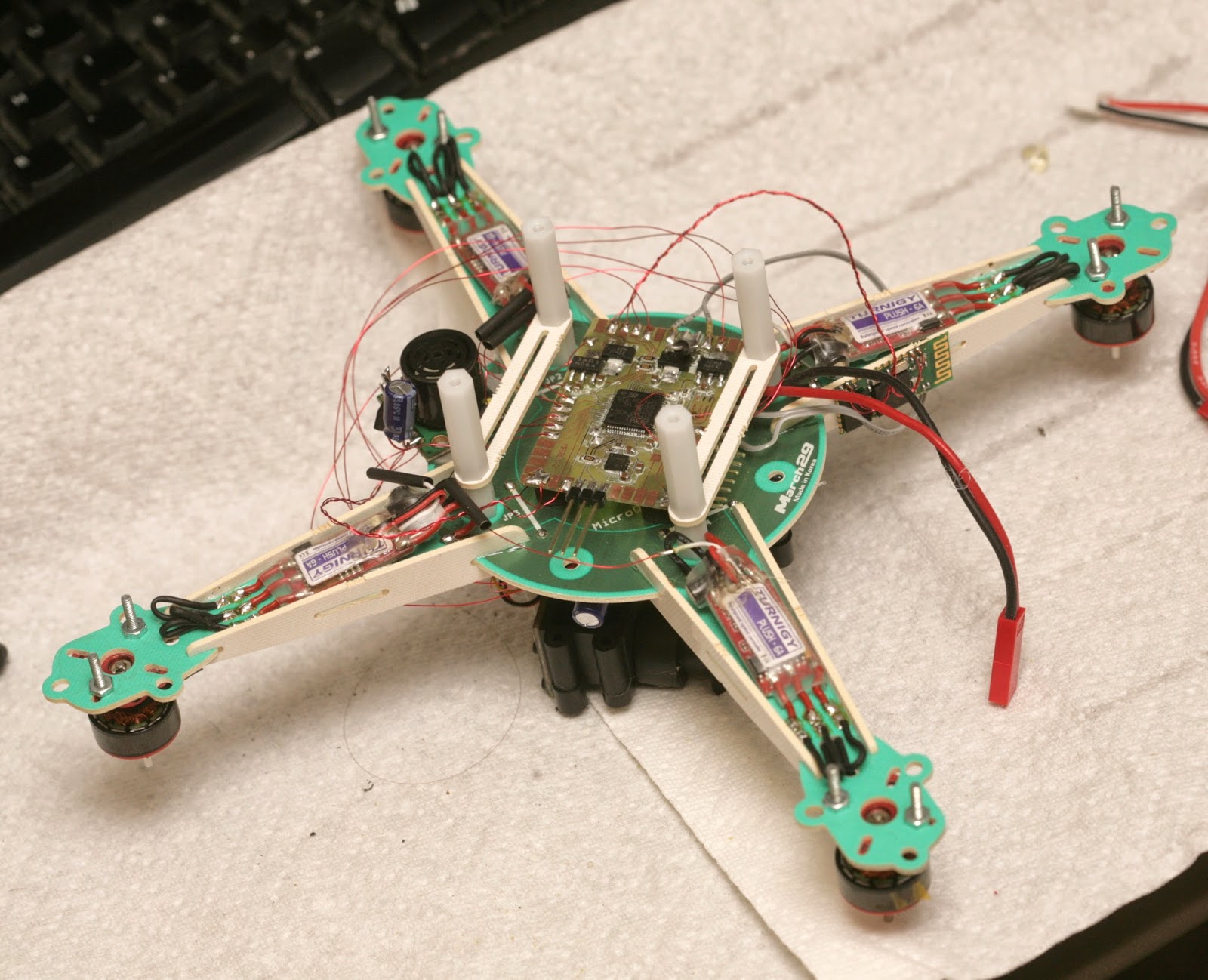
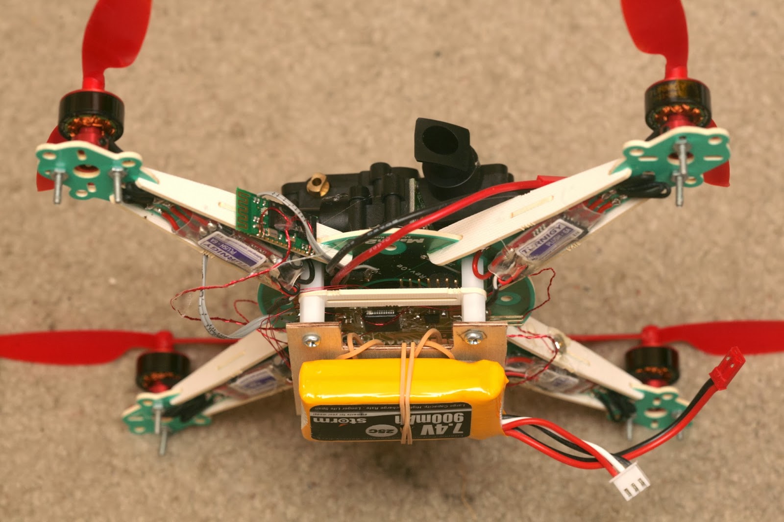
The Turnigy Microquad has the highest capacity for its size.
It's single sided PC boards, conventionally routed. No 3D printing, laser cutting, or anything else.
The landing gear is made out of PC board standoffs.
The motor mounts need a lot more reinforcement. Some guys glue on carbon fiber or plywood doublers.
It has enough clearance for the PX4flow. The battery needs to go on top, over the mane board.
Taking a page from the AR Drone, the battery is used to weigh down the IMU.
It's the most energetic platform so far, definitely not a toy. Those Turnigy 1811-2900's get a lot more thrust from the same space as brushed motors.
The PX4FLOW's 1st flight
Based on the previous video of the TCM8230 over carpet, the PX4FLOW is a huge improvement. It actually holds position quite well over plush carpet & below 1m.
The sonar still has issues above 1m. It glitches to 5m when it can't detect a reflection. Sometimes you want it to send 0 when it reads 5m & sometimes you want it to repeat the previous reading when it reads 5m. It still glitches, despite this algorithm.
It's very heavy, so it handles the wind quite well. Crashes require a lot of repairs & propellers. It's every bit as crash prone & fragile as expected. Every day of flying requires a bag of propellers. The propeller mounts tend to break off.
It's time to fuse a barometer with the sonar to try to improve the range over carpet.
The jesus barometer goes on.
& gets earplug foam insulation. Earplugs are decent sources of breathable foam.
The temperature compensated MS5611 output
is compared with the raw MB1240 output
in a 1m flight over carpet. Despite the temperature compensation, the MS5611 has a huge amount of drift, leading to 1m of unknown absolute error. Its short term relative readings are quite good for something that measures air pressure.
For the 1st time, you can see just how many sonar readings are invalid. It generates 7650 when it knows the reading is invalid, but sometimes it errors low. It never seems to error high.
The object of the game is to fuse the air pressure & sonar readings to eliminate the errors. Sonar still has to be the master.
In this flight, the last 10 pressure readings are averaged & normalized to the average of the last 10 sonar readings to compensate for temperature drift. The most recent pressure reading is subtracted from the average pressure & scaled to mm to get the most recent altitude based on pressure.
The algorithm doesn't produce any glitches, but is very noisy compared to sonar. You want to use sonar if the sonar change is under 100mm. If it's over 100mm, use air pressure.
A flight using fused sensors for guidance was very smooth, but overshot the altitude changes a lot more. It switched to pressure, which lagged sonar. The sudden altitude changes due to glitches were gone, but there were audible glitches in motor speed.
The PX4flow has presented a case of far sightedness. It's most accurate at 1m altitude. Below 1m altitude, it has a very hard time detecting position. Above 1m, the sonar falls over. The focus can be adjusted for lower altitude, but it has to fly in a narrow altitude band. That's the price of a very high magnification, high brightness lens which can detect surface features from far away.
A 2nd camera would have benefited the low altitudes, but there wasn't enough time to discover the PX4flow limits & design a 2 camera optical flow solution.
That's probably the most aggressively something has ever flown itself using optical flow. Optical flow has previously just been used for aiding a human pilot in a hover.
So the PX4flow has a very low top speed. The horizontal velocity has to be limited to 0.25m/s. Vertical velocity has to be limited to 0.1m/s. The mane problem is what kind of carpet it has. Its top speed in the plush apartment carpet seemed to be higher than the finely colored office carpet. The mane problem with altitude is it's clearly switching to the barometer more for high speeds & the barometer has much more lag.
The flight time with the PX4flow weighing it down was slightly better than the Syma X1 at 7 minutes.
The power distribution on the microquad interferes with the magnetometer. It needs to be on a mast.
Found the story intriguing. Batteries remane fickle things. Their total charge is still only estimated by stopwatches & coulomb counters, but there is no dip stick for a battery. Even a pilot experienced enough to keep 1 eye on the flight time while the other eye is on the 5000 other details still is often surprised when a battery comes up empty ahead of schedule.
Sometimes you forget to charge batteries. Battery chargers sometimes don't finish charging because they overheat or their own supply sags. Sometimes they don't start charging because of a balky button or a poorly designed user interface. Sometimes they report maximum voltage despite no longer holding a full charge.
A return to launch feature when the battery is low also remanes fickle. GPS comes & goes anywhere besides a wide open field. Is the return to launch feature supposed to count coulombs & maintain a database of every battery's capacity in order to determine when to end the flight? Should the pilot enter in the current battery ID or should the batteries have ID chips, raising the cost & complexity?
It's yet another one of the variables & details that keeping something in the air still involves keeping your mind on. There is still a lot of room in the current state of reliability to keep the price, complexity & training beyond the reach of hobbyists before the personal drone becomes as ubiquitious & hand off as the marketing campaigns depict.
So Bre Pettis finally sold Makerbot Industries for 1/2 billion dollars. It definitely puts your monthly ABS budget & the concerns of whether to splurge on the 2 color extruder in perspective when you realize the founder walked away with at least 1/4 billion dollars.
Once again, it's not the revenue from Makerbot sales or speculation on the value of being able to print goods, but the enormous library of widgets users of the Makerbot submitted to thingiverse.com for free, over 100,000 in total, & which Bre was able to monetize with the acquisition. Like the instagram & tumblr acquisitions, a massive amount of data was created for free while the true value of it was monetized by just a few individuals. Is that the way open source hardware is supposed to work?
The answer we're supposed to give is yes, the world should be based on legions of people producing data for free & the true value of that data being concentrated into 1 top individual in these massive buyouts. The creators of the data should not be compensated because we all want to be the top guy.
We've had these massive payouts for data since the internet got big in 1999 & the amount of data that cost nothing to download became truly massive. Initially they were in the form of the Redhat, VA Research IPOs, later in the form of the modern social network giga acquisitions, maybe now the open hardware giga acquisitions.
The concept of data that we create in full faith that it's supposedly free having a massive amount of monetary value in the invisible hand of the economy isn't going away. Neither is a landlord going to turn around & open source his rental properties just because we provided the data that paid for his assets for free. It's well known that wealth is being concentrated at the top a lot more than it ever was & times are much harder for the rest of us than our parents.
But what if the creators of the data were compensated in the buyouts instead of the total amount being focused at the top guy? Would the creators of the data not be able to hire people on their own, create jobs, buy stuff on their own?
Active cooling has been a cheap way to get more power out of underrated motors. You want as much power as the motors can handle. When you can't afford a variety of motors, there's active cooling.
Testing with the narrowest field of view, the slightest motor cogging is revealed.
Got the tiny motors up to .9A with active cooling. The pitch still has .3A without active cooling, to minimize vibration. The tiny motors have the least cogging artifacts, so active cooling might get them all the way. It's never going to be perfect, without bigger motors.
10 bit PWM, 1024 step sin table added a tiny bit of precision. No amount of power or PWM precision could completely eliminate cogging. 8khz, 32khz, shifting the magnets away from the stator didn't matter. If you don't get a bog standard gimbal for $100, you'll end up paying more to find ideal motors.
Slightly better in the running timelapse with software stabilization, which means it could be superb when flying. For a running timelapse, it's probably not worth supporting yaw or pitch at all, if software stabilization is required. A simple roll stabilizer is what you want for running.
Wound up a 3rd Turnigy 2205 1350kv for the yaw. Grinding off the enclosure made it a lot easier & opened up more airflow. It was just about as easy as a DT700. The enclosure served no purpose.
Aluminum cooled it off a bit better.
Given enough current, active cooling, a high resolution DAC, brushless motors have a lot of potential in highly accurate pointing. A 16 bit DAC can get 65535 steps in 90 deg. They don't need an IMU.
There were some test videos using the passively cooled DT750, revealing how much worse the cogging & the roll was without enough power.
Brushless motors would have made a decent laser projector, years ago. Kids were making stepper motors for laser projectors, but they had to machine the bearings. No-one realized a hobby motor or a fan motor could be used for a pointing task.
Look how well you can navigate using just el cheapo optical flow odometry & sonar. Over carpet, 0.5 meters is all you get before the camera loses velocity detection. Over the floor pattern, it can do 2 meters.
Went back to position->velocity->tilt feedback. That was done in 2007, then changed to position->tilt in 2008, when GPS got good enough. For very precise indoor navigation, position->velocity->tilt feedback seems to be better. This seems to be what Arducopter also uses.
Originally saw position->tilt in Mikrokopter when it was open source, thinking it was going to be the standard design. It was faster, but caused more toilet bowl effect. That crazy German even used position->throttle for altitude.
Vision guidance doesn't have doppler shift, which makes velocity delayed. Also, the IMU drifts too much to limit velocity by clamping tilt at a reasonable value. You have to clamp velocity so a long movement doesn't go out of control.
Increased the optical flow frame rate to 50. There is always a hunt for the highest frame rate before the minimum speed becomes too high, yet not too slow to have too much error. Those improvements made it pretty damn stable.
There were some cheap optical flow floor covers at the dollar store. It takes painting 3 with a dry brush to create a reasonable flying space.
No better than unrolled garbage bags, but the most compact material. Can't imagine who would ever use them as table covers.
The 1st board which didn't have any defects. It worked on the 1st power up. It makes sense, because after that, you realized you needed a day job.
Didn't have much luck with the MB1043 but the MB1240 was golden. That can range useful altitudes over carpet, with the propeller noise. mm or cm accuracy didn't make any difference.
It's hard to conceive a business model for something that flies for only 5 minutes & needs a special floor. The AR Drone did it by implementing an easy programming language & having enough spare clockcycles for developers to process the video. Something smaller, with no spare clockcycles would be harder.
Basically, the roll & yaw motors trade places as IMU2 pitch goes from 0 to 90. The PID equations have a set of gains for the upright position & a set of gains for the swapped position. The PID equations for the motors are always solved for fully upright & fully swapped. The PID outputs are then blended based on the actual IMU2 state.
The gradient isn't linear. It's a sine wave. When IMU2 is pitched 20 deg over, it adds just 12% of the roll. When it's at 45 deg pitch, it adds 50% of the roll. When it's at 70 deg pitch, it adds 88% of the pitch.
The yaw motor output fades to 0 as IMU2 roll goes from 0 to 90. The world will undoubtedly move to a better algorithm involving a discrete cosine of some kind, but this solution seems to do the job, in the meantime.
The algorithm worked as described. The yaw motor could move anywhere without a loss of control, though this frame has very limited roll freedom. It was the 1st time the yaw coupling problem was solved outside China. At least for a short time, no-one else in America could do it. The mane problems are now a very wobbly frame, lots of cables binding, too much cogging in the DT700.
Both IMU's required heavy, shielded cable. There was once a page which said to only solder 1 end of a cable shield, to avoid ground loops. http://en.wikipedia.org/wiki/Shielded_cable
After fighting I2C glitches forever, remembering a Logitec webcam was connected to both ends of the shield, decided to solder both ends of the shield. That ended all the interference. So for an I2C device where the only return path is the signal cable, you need to ground both ends of the shield.
The forums & the experience of tuning the gimbal showed there is a limit to the amount of motion it can isolate. The amount of power, the speed of the feedback, the inertia in the camera, the amount of time spent perfecting PID gains, the speed of the MOSFETs, all conspire to limit its effectiveness. Brushless gimbals probably won't be stable enough for handheld astrophotography.
The gimbal has 1150hz feedback & a sin table with 1024 steps. The MPU9150 needed to be set to 2000 deg/sec to handle the oscillation of overdriven PID gains. The digital lowpass filter was disabled. Increasing sin table resolution had a noticeable impact on the motor smoothness.
The controller applies a constant current to the motor, regardless of the amount of motion. This should be the highest the power supply & motor can handle.
Unconventional trick to get by without a solder mask.
The yaw motor is 130 turns of 0.2mm on a DT700. It could handle 0.6A.
The pitch & roll motors were 50 turns of 0.2mm on a Turnigy 2205 1350kv. It could handle 0.3A. Ideally, it would be more turns of lower gauge wire. The forums recommend as many turns as possible.
Buying pre-wound motors is initially worth the extra money, but the selection is very limited. Once you've mastered winding, you're better off winding your own.
All these motors need to be heated to be unwound. Start the unwinding at the cable terminations, not by cutting into the windings. Make new windings with a narrow plastic tube. A long piece of wire insulation seemed to work best. The Turnigy 2205's were busters. They might be easier by grinding off as much of the enclosure as possible, without removing the screw holes.
The problems with traditional 2 axis & 3 axis gimbals were documented. So basically, not knowing the orientation of the roll motor prevents any traditional gimbal from being an ideal isolator from all possible movements. The magnetic heading is probably not going to be available either, since it's influenced by the motors.
Yaw is coupled to roll/pitch when tilted outside a very narrow angle.
The 2 axis gimbal did a real lousy job stabilizing handheld footage. On an aircraft, a 2 axis gimbal is probably good enough. You can probably use the flight controller's IMU to aid the roll motor.
The copter flies away & returns to the starting point at 2 different altitudes, using only optical flow odometry for position & sonar for altitude. The fact that it landed at nearly the takeoff position was probably coincidence, but optical flow has proven very accurate in a 30 second hover. It may depend more on time than movement.
For the 1st time in many years, the entire autopilot was on board. Only configuration parameters are still stored on the ground station.
The takeoff is hard coded for a certain battery charge. This battery may have put out a lot more than the battery it was hard coded for, causing it to bounce during the takeoff. Nothing optical flow guided besides the AR Drone has been shown doing autonomous takeoffs & landings. It takes a lot of magic.
It was a lot more stable than the ground based camera. Ground based vision had a hard time seeing the angle of movement, relative to the copter. Optical flow has precise X & Y detection in copter frame.
How long can they stay in bounds? The mini AR Drone did surprisingly well, compared to the commercially successful AR Drone. The degradation was reasonable for a camera with 1/3 the resolution & 2/3 the frame rate. It's not likely to get more accurate. The mane problem is glitches in the Maxbotix.
Optical flow can hover for around 90 seconds at 0.5m before slipping off the floor pattern. Above 1m, it slips off after 1 minute. At 1.5m, it slips off after 30 seconds. The Maxbotix falls apart at 1.5m over posterboard.
The mane requirement in optical flow is the angular motion needs to be very accurately eliminated or it won't work at all. Using the IMU gyros works well. This is done by adjusting a 2nd pair of gyro scale values until rotating the camera doesn't produce a position change.
The heading & altitude need to be factored in when integrating optical flow or it won't accurately calculate position. The academic way to convert pixels to ground distance involves a tan of the pixel shift to compensate for parallax, then multiply by the altitude. The pixels are so small, the parallax was neglected & the pixel shift was just multiplied by altitude.
Optical flow initially needs to be tested on something like this:
To gain enough confidence & calibrate it enough to start integrating it on this:
A lot of energy went into finding the optimum floor pattern.
So the optimum pattern seems to be random splotches of paint with dry brushing in a grid. Too much brushing makes it too smooth. A few gallons of toner would be nice. A laser printer could get the optimum fractal pattern perfect.
For all the energy going into making robots navigate human environments, there's no pondering of the idea of making human environments navigable for robots. Floors with optical flow patterns would be a lot easier than LIDAR.
Straight lines of featureless tape were the worst. It seems to rely on texture of the paint up close, while painted patterns far away. The only way to get a pattern big enough to fill the flying area with enough reflection for sonar is paint on a plastic drop cloth.
The worst patterns require a higher minimum motion. The best patterns cause the least minimum motion to be detected. The pattern affects the outcome more than the frame rate or resolution.
Long & boring video documenting interference between wifi & the Maxbotix MB1043, the world's most temperamental sensor. Some orientations do better than others. The Maxbotix & wifi wouldn't be very useful on any smaller vehicle.
A totally random orientation of wire & dongle was required. Wire orientation, wire insulation, dongle orientation, dongle distance all determined whether the Maxbotix died. Any slight movement of the wire breaks it.
The automatic takeoff & altitude hold were extremely accurate. The 10Hz update rate wasn't as problematic as feared.
So basically, after 6 years, the Maxbotix still has to be powered up facing away from the ground or it returns bogus values. This continues to be the greatest scourge of sonar navigation. The Parallax sensor in the AR Drone initializes properly with no clearance.
It still needs an external RC filter to filter the power supply. You'd think they would have found a way to store the calibration data on the flash or make a bigger board with integrated power filter to generate the best readings.
The Maxbotix still requires a manual trigger to range at its maximum rate of 10Hz, but it repeats the same value if triggered at less than 25Hz. It needs to be triggered at 50Hz to output 10Hz of unique data.
Flying it manually with the tablet is reasonably easy.
The mini AR Drone has an MPU9150 read at 1100Hz for the gyros, 125Hz for the accelerometers & mag. The PWM is 2000Hz. The IMU needs liberal foam padding or the attitude readout drifts too fast.
It turns out USB host on the STM32F407 interferes with I2C, so you can't read the IMU when wifi is on. It has nothing to do with RF interference. The IMU has to be driven off a secondary microprocessor & the data forwarded on a UART. It needed a 400khz UART to transfer the readings fast enough.
There's at least 0.5ms of extra delay to get the readings from the I2C breakout processor to the mane processor. The I2C interface itself has at least 0.4ms of delay to get the voltage from the gyro. In total, it could take 1ms for a motion to be detected. Such is the sacrifice of reading out an IMU on I2C. The delays from movement to digital reading are what make instability. It's not unlike the AR Drone, which has a second microprocessor read the I2C sensors.
The electronics with wifi use 300mA. Wifi sends 2 megabits, manely consisting of the optical flow preview video. Star grounding & star power supply were required for anything to work. Having everything except the motors behind a 3.3V regulator & 1000uF of capacitance was required.
Wifi was especially sensitive to voltage glitches, making running on a 4.2V battery with lousy MIC5205 regulators extra hard. The MIC5353 would be a much better experience.
After years of dicking around with charge pumps, pullup resistors, & BJT's to turn on MOSFETs that require 5V to turn on, finally got around to probing the Syma X1's board. It uses a MOSFET that turns on at 2.5V, the 9926A. The 9926A is an extremely popular dual MOSFET made by many manufacturers.
The electronics weigh around the same as a PX4Flow, except using the PX4Flow would have required another board in addition to it. The PX4flow was ruled out because of the weight & the size being too big to fit anywhere.
PX4Flow weight: 17.5g
With the PX4Flow connected to USB & Qgroundcontrol fired up on a Mac, it was immediately clear that it had a very long, sharp, macro lens, allowing it to resolve texture from far away.
Setting it to low light mode produced a noisier image. In any mode, the position updates came in at 100Hz, despite the sensor capturing 200Hz.
It didn't need any calibration. Just connect it & it outputs Mavlink position packets. The lens was already focused. It outputs packets at 100Hz on USART 3 but not USART2. It seems to run as low as 3.3V at 120mA. Below that, current drops & LEDs start going out. Above that until the 5V maximum, current is constant.
Most of what the PX4Flow does was redone on a new board, with the TCM8230. The autopilot was implemented on the same chip. The optical flow only does single pixel accuracy, 42fps. It crops to get a similar narrow field of view. It scans a 96x96 area instead of the PX4flow's 64x64. The scan radius is 8 pixels instead of the PX4flow's 4.
It requires a more detailed surface than the PX4Flow. The optimum combination of camera contrast, motion distance, frame rate, & scan radius dictated the camera run at 320x240. Running a higher frame rate or resolution made the camera less sensitive & blurrier in the X direction.
Also, the PX4flow uses a histogram of the motion vectors. Found better results from a straight average of the motion vectors.
Assembly language made an incremental improvement in the scanning speed, but the mane limitation still seemed to be memory access. The scanning area & scan radius would probably have to be slightly smaller in C.
The Goog couldn't find any examples of vectored thumb inline assembly, so it was a matter of trial & error. The STM32F4 programming manual, inline assembler cookbook, & STM32 Discovery firmware are your biggest allies in this part of the adventure.
It turns out there are no NEON instructions in thumb mode. Thumb mode has yet another set of vectored instructions with no special name.
For the 1st time ever, it's the inline assembly language absolute difference of an 8x8 macroblock:
As expected for an undamped, strictly proportional feedback system, it bounces off walls faster & faster until it crashes. It can't hover stationary, from the reflected IR. Walls not completely reflective, not completely seemless, or not orthogonal to the sensors are less effective.
To engage the altitude hold, fly above 0.2m & get it to settle into a descent with fixed throttle. It automatically fixes it at 0.2m. It seems to work over carpet.
Any reflected sunlight pushes it away from a long distance. The feedback makes it harder to fly manually, as the ever changing sensor angles & reflectivity of the walls constantly create random amounts of unbalancing. It uses a 600mAh battery, a new record for a copter this small. The increased weight destroys the propellers in crashes a lot faster than the old Ladybird.
The amount of site preparation to get the perfect reflections & lack of any damping show why IR hasn't taken the job of localization from optical flow. It's easier to lay down a reflective floor than set up perfect walls.
It does have longer landing gear than the Ladybird, probably to meet the clearance requirement for sonar to initialize.
All the IR sensing, flight control, & radio is on 1 board, complete with MOSFETs, snubber diodes, extra space for the LED headers, an extra connector for the flashing LEDs. It has a pot for adjusting the heading sensitivity, but it's too much work to unplug all 8 IR connectors to get to this board.
A TI CD4069 hex inverter drives 1 transducer. A bag of Microchip 6L04 op-amps amplify the other transducer. The mane atmel controls everything. This board has headers for the IR receivers, so some of the op-amps probably go to IR.
Standard Cypress radio & Invensense gyro, with rubber shock absorbers. This board has headers for the IR emitters. Whether or not it was intended, all the noisy motor power is on this board, while the IR & sonar amplifiers are on the other board.
Anyways, looking at how it was manufactured, each LED & photodiode painstakingly taped down by hand & connected with its own JST connector into a tiny nest of 16 wires, someone with a lot of power & labor at his disposal decided this was going to work. He was convincing enough to shift a lot of money to making it.
Meanwhile, the Marcy class aircraft, which have worked better with less site preparation since Jan 2012, have never won any investment. It's more about how it's sold, rather than how well it works. Selling it as an experimental model to RC pilots wins them over, but selling it as a machine which can cook toast & fly it into your mouth is going to get you laughed out of China, no matter how much better at being an RC model it is than anything else.
Everyone wants a high volume consumer product, but UAV's are such a high profile product, even the dumbest suits can't be fooled when the current state of flying robot technology doesn't match the sales pitch.


