Jack Crossfire's Posts (188)

Sort by

1st spinning camera footage

motor17.jpg

motor18.jpg

esc02.jpg


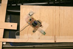
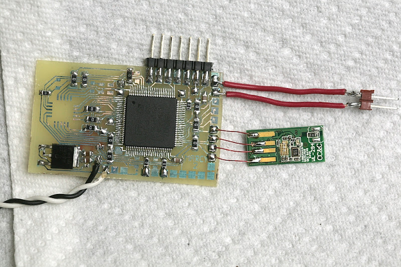
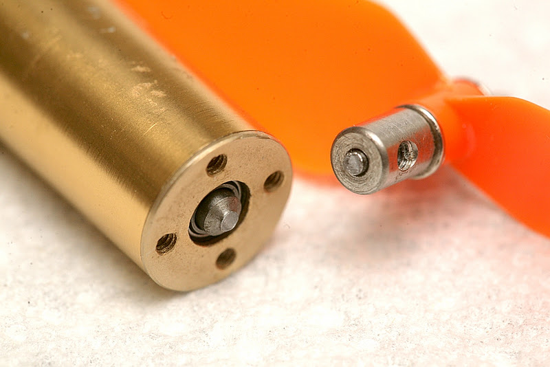
Marcy 2's power plant is overpriced junk from Tower Hobbies.  They didn't send the $1.50 of Dean connectors ordered.

The Castle Creations 6 is really badly soldered.  The 12-30-4110kV Electrifly has incredibly flimsy wires.  It's obviously high flex cable & I should have left the bullet connectors on, but they looked heavier than they were & they easily broke off.

marcy2_34.jpg

marcy2_33.jpg

marcy2_32.jpg

marcy2_35.jpg


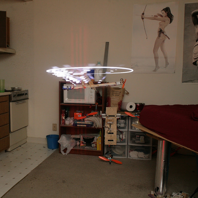
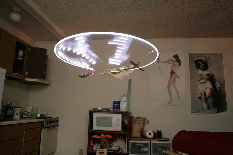
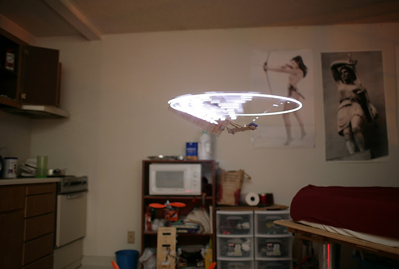
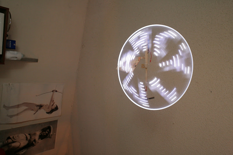
She does indeed fly.  Video points nearly sideways.
images01.jpg


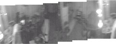
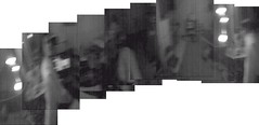
 The 1st images at flight RPM were pretty bad.  A refrigerator & chair are visible.

Instead of hitting head on, the camera scanned diagonally, causing sheering in addition to vertical compression.  At the highest shutter speed, it was still pretty blurry.  Each revolution has 6 frames, so forget about lining up a frame on the same spot.

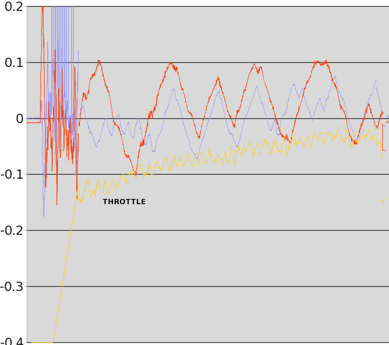
The test harness was pretty unstable.  A stable attitude would give better results.


marcy2_36

  
images02

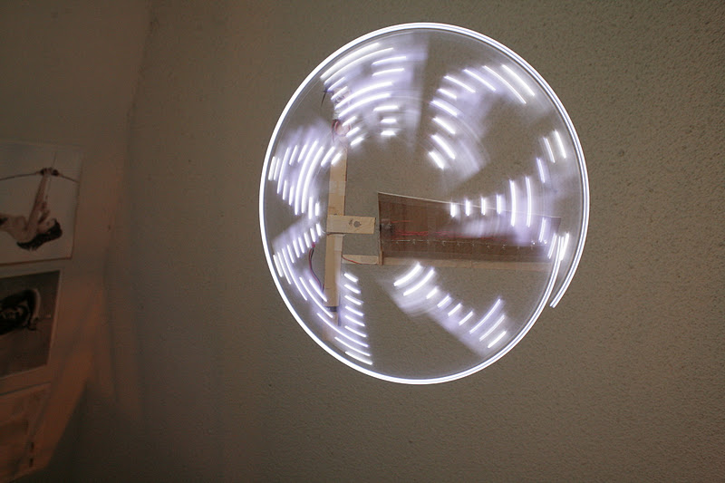
 Camera rotation improved matters.


images03


Increasing the camera to 30fps, letting it drop 1/2 the frames, & letting it drop magnetometer samples got more overlap.  If there was a way to automatically align everything, this might work.  Slow scan 640x480 was useless.  The trend is towards lower resolution & higher clockspeed.
images04
images05

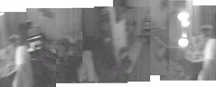
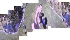
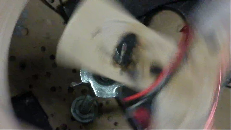
Next, we have 160x240 with every frame sent twice to reduce dropped frames & full magnetometer data.  A lion is clearly visible.

images06

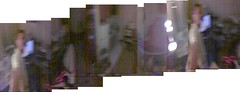
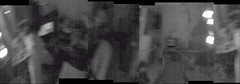
Finally, a shot in color 160x240 at 24fps, with 1/2 the frames dropped.  More detail is recognizable to a human, but probably not to a computer.


It's hardly the sharp daylight footage envisioned, but this is a matter of the size of the lens & the sensor quality, not available technology.


Ride on a monocopter

Since the camera is going to point diagonally, it's hard to envision a target it could use for navigation.
mane_attack.jpg

Trying to spin up Marcy 2 outside resulted in the wind taking her off & the mane immediately being attacked.  Untangling required destroying the propeller, since press-on propellers can't be removed.


images07

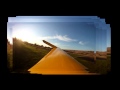
At least it showed daylight improved the picture quality & a monocopter could be very useful for imaging outside.

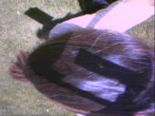
 Automatic placement didn't go so well.


images08

 Rotating manually matched a little better, but since the camera was pointing diagonally, it only needed 90 degrees of rotation.  If it pointed straight down, it would rotate 360 deg.
Playing with the Marcy 2 cam showed the realtime 360 deg panorama isn't going to happen.  There's no way to align all the frames fast enough & the information is too noisy to convert to an altitude & position.
Next comes shooting 1 frame per rotation at the highest framerate possible, so the 1 frame can be as close to the same position as possible & capture the highest resolution in the direction of rotation. 

There's no way to trigger the camera at any random time. The nearest frame jumps around a lot more as the framerate decreases.  The extra processing for color slows it down by nearly 1/2.
A slower framerate to increase the span of each frame by widening the line spacing was disastrous.  It really needs the tightest line spacing possible.
It can probably go higher than 42fps if only 1 frame per rotation is captured & the frame buffer is diabolically hacked.  40Mhz is the maximum that any home made solder traces ever did.  It's currently doing 42Mhz to get 42fps.
If there was any advantage to using a custom board instead of http://www.8devices.com/product/3/carambola/specs it was the ability to get very high framerates from the camera interface.  A USB webcam on the Carambola would be real slow. 

  The coning angle is a lot steeper than expected, making pointing straight down hard.

Now some useful commands for accessing Marcy 2 without compiling a wireless network driver on every computer.

iptables -t nat -A POSTROUTING -j MASQUERADE
echo "1" > /proc/sys/net/ipv4/ip_forward

on the computer with the network driver.

route add 192.168.0.1 gw amazon

on the computer with the ground station.
marcy2_31.jpg
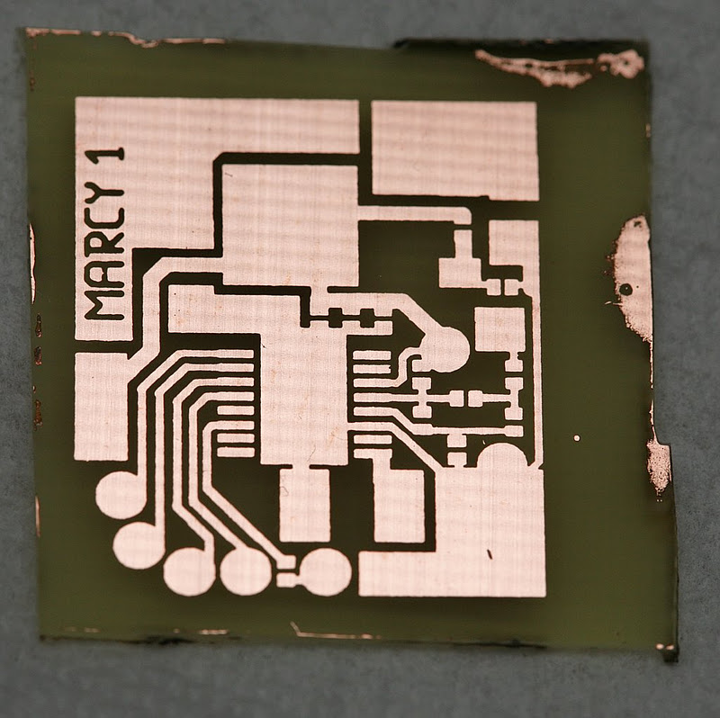
That there is a board so badly designed, it's nothing but rework.  The mane shock was a TO-252 had the lowest current capacity of all the LM317 packages & this board uses a lot of current.  If money was infinite, a low dropout regulator would be used. 
mag27.jpg
marcy2_28.jpg
After many experiments, it turned out the STM32F4 I2C core sux.  Software I2C solved the timeouts & it may be ignoring the ACK was the key to RF robustness.  Software also went a lot faster.  The hardware I2C may have added delays somewhere, to comply with the spec.

No matter how high the clockspeed, hardware I2C never could get over 64 samples/sec.  Software could do 120 samples/sec.  Video framerate had to drop & the DCT needed a lot of I2C polling between those raster lines.  10k pullup resistors were necessary.  The STM32F4 has 50k pullups.
screenshot01.png

  There's something you never thought would happen.  Full telemetry & video over wifi.  Depending on the video detail, it'll go up to 4 megabits.  It's not as much telemetry as a quad copter, but the 2.4Ghz bitrate is slightly higher.

Read more…

I2C woes

marcy2_20.jpg


Stepped the wireless down to 11megabit & the range definitely increased.  It uses a lot more power because the transmitter is on longer, but the penetration is much better. 


Found another 64k of RAM on the STM32F4.  It's the fabled core coupled memory, bringing the chip up to 192k.  That increased the framerates.

640x480 color: 5fps  1.4 megabits
640x480 greyscale: 7fps   1.8 megabits
320x240 color: 23fps 2.5 megabits
320x240 greyscale: 30fps 2.5 megabits

The trick with the core coupled memory is it can't be accessed by any peripherals.  The network now needs a memcpy.  The mane benefit is there's enough RAM to have the largest buffers, all the time.  The camera can be in 320x240 greyscale for navigation, than briefly switch to 640x480 color for a photo, without having to shuffle buffers around.

There are also 320x480 & 160x240 modes.  The theory with this is a rolling shutter camera can be used in pushbroom mode, capturing a wider field of view by compressing the vertical lines.  The resolution becomes equivalent to 2 320x240 images stacked on top of each other.

320x480 greyscale: 14fps
320x480 color: 9fps

160x240 color: 30fps

160x200 is Commodore 64 resolution. 


The camera was damaged from pointing at the sun.  It didn't generate hot pixels, but made areas more blue.  Between hot air melting & sun damage, it's real fragile. 

Spending 2 days optimizing different video modes was a waste, but it might have come in handy for any job interviews.  Times have changed.  Job interviews today are straight programming tests from Google's interviewing style.  They're not interested in applications, but very specific knowledge about a programming language.  Google is presumed to be the handbook for everything.


The tasks of PWM, battery sensing, & magnetometer reading, which are the bread & butter of aviation, sure look mundane once you get video going.  The STM32F4 makes life a lot easier with pullups on all the GPIO pins & 2 32 bit timers, allowing 8 channels of 200 Hz PWM with no funky interrupt handling.

The magnetometer used in Marcy 1 & Marcy 2 was a freebie AK8975, which came at a cost.  It's sold in 32 piece minimum quantities & costs $6.  You're looking at $200 just to get started.  Almost anything is cheaper.   The HMC5883 is $4 & has an I2C interface.  It's most certain that every production run of Marcy 2's would have completely different parts.


There's actually a chance video could do the job of the magnetometer.  To be sure, Chinese toys have used video of sorts to stay in a certain horizontal position forever.

marcy2_21.jpg


Airframe assembly begins.

marcy2_22.jpg


akm8975_02.jpg


It's been ages since I ever removed the photoresist or actively tinned anything.  Tinning would definitely make it heavier.

marcy2_23.jpg


That is a heavy board.  The bottom of the camera faces the leading edge, so the scanlines cover a longer distance than a single frame.

This arrangement immediately caused the RF emissions to crash I2C.

marcy2_24.jpg

marcy2_25.jpg

marcy2_26.jpg


Various attempts to defeat it failed.  Lower pullup resistors on I2c, routing the I2C away from the wifi, moving the wifi away from the motherboard didn't work.  It's just going to be limited to 40 samples/sec by the RF.  The same thing happened on Vika 1 with the XBee. 

Marcy 1 needed 112 samples/sec & got that with a long I2C cable, but a very low power radio.  Cell phones must have a lot of shielding between their I2C sensors & the RF.  The AR drone has the Wifi on the opposite side as the analog sensors.

Seem to recall having a dream about fixing I2C on this board.

Read more…

Kickstarter thoughts

kickstarter.png

If you don't have dreams of launching a UAV project on kickstarter, making zillions of dollars, & quitting your unemployment compensation, you're crazy.  So here's a quick graph of kickstarter funding for "currently funding" LA projects, which is the easiest data to find on their mane page. This was the only easily copyable data set & includes all the future unsuccessful & successful projects.

Out of 334 projects, most of them are getting from 0 to $5000.  There's a definite preference among the crowd to cluster above $15,000 & avoid below $15,000.  The top 24 projects earn more than the sum of the bottom 310 projects & the top 4 of projects own 19% of the total wealth.

It's definitely flatter than wealth distributed by the government, but even with the crowd, the trend is definitely the same.  You see the same trend of concentration of wealth near the very top in food, longevity, dating & marriage.  It's hard to beat biologically wired behavior.

 Assuming you want something to break even & you're American, so you're probably unemployed, you need around $2000 to pay 1 month of the cost of living + the cost of parts in the widget + taxes.


Kickstarter takes 5% of the cut for their CEO running a server & Jeff Bezos charges another 5% for being Jeff Bezos credit card processing.  Anything not spent on your own business expenses, kickstarter reports to the IRS as ordinary income, so you have to pay another 10-30% in taxes.  Fortunately, if you're American, your taxes should be under 10% because you're unemployed.

If your cost of living is your margin & you shoot for no profit, you're looking at $400 of taxes + $2000 to survive + parts, for every month it takes to produce the thing. 


If it takes 1 month to finish all the orders & the widget has no parts, you need to be better than 29% of the projects.  In reality, nothing is finished in 1 month.

For a real focused job, a real simple widget, producing exactly what the customers want & no diversion to your own needs, you're looking at 3 months or $7200.  Attopilot took at least a year or over $28,800 just for the cost of living + taxes.  Only the top 2% make that much on kickstarter.

 The money is conceivably easier, but how many of those kickstarter investments are really due to kickstarter clicks & not people the maker didn't already have a network with or the maker worked his ass off selling to?

At least 1 investment is going to be from the mother.  I suspect most of the money is coming from pavement pounding sales.  Kickstarter of course, would insist that all the money was because of clicks.

As a way to replace your day job, fuggedaboutit.  As supplimental income on top of a day job, it's certainly there.  You won't make as much on kickstarter as you would putting the same amount of time into a day job, but it could certainly allow you to build something.

It may not allow you to think very far outside the box.  Unless you're Steve Jobless, people don't buy stuff that's too different.  What could be real crazy if you went with your own money has to be a bit more conforming to get someone else to pay in advance.

There's never a free lunch.  When you ask for advance payments, you have to deliver what customers think they want & that is never exactly what you want.  You always have to give up some freedom to get someone else to take the risk, whether it's a crowd or a government.

Read more…

Wifi cam complete

Various modes of Marcy 2's fully functioning wifi camera are shown. A 168Mhz 128k RAM chip compresses JPEG & streams on 802.11g. As the frame size increases & color is enabled, the framerate goes down. Body movement around the antenna makes it drop packets. It still compresses a lot faster on 168Mhz & 128k RAM than a 166Mhz Cyrix with 64MB SDRAM did, 15 years ago. The Cyrix only did 5fps 320x240 color, if you were lucky.


With a new, unmelted camera finally arriving, the true frame rates & bit rates could be known.

640x480 color: 3fps    800 kbit
640x480 grey: 4fps    1 megabit
320x240 color: 20fps    2.5 megabit
320x240 grey: 30fps     3 megabit


Quite an improvement over the UART cams from Sparkfun.  The bitrate got a lot higher when the lens wasn't melted.  All the 640x480 modes had to go to single buffers to fit in the RAM.  They could double buffer if the quality was reduced way down.  Noise is now the real problem.  Capacitance directly on the wireless dongle is the key.  Networking bitrate is way up.  Bluetooth wouldn't be an option.


320x240.jpg

320x240c.jpg


640x480.jpg

640x480c.jpg


desolder01.jpg


Desoldering position for the melted cam.

cam81.jpg


Another $20 in Nate's retirement fund.

cam83.jpg


Another perfect soldering job.

cam84.jpg


Marcy 2's eye.

marcy2_19.jpg

 The TCM8230MD does run on as low a clockspeed as you want, giving a much brighter picture & a data rate suitable for 8 bit micros.  The rolling shutter got bad at 1Mhz.  It's certainly no good for aerial photos at 1Mhz.  Rolling shutter is much less at 28Mhz.


It would be revealing to know how bad the AR drone cameras are, but the guys who use those don't know what a rolling shutter is.

For video compression, some research led back to rtjpeg, an ancient piece of code from the early days of video.  A guy spent a lot of time making the simplest, fastest DCT image compressor possible.  It's totally impractical for video editing on today's computers, but perfect for embedded microcontrollers.

A port of RTJPEG & a step up in optimization flags got the frame rate way up.  The trick was compressing the DMA buffers directly & doing the whole process from camera to network without any mem copies.  For greyscale, it compresses 8 lines at a time, as the frame is read from the camera.  For color, it compresses 16 lines at a time.  Thus only 128k RAM can compress 640x480 color.


The camera generates much less noise when underclocked below 4Mhz, but the rolling shutter is really bad.  The network is very prone to going down or dropping out during a high bitrate stream, since the chip doesn't have enough bandwidth to service ASSOC requests while streaming at full speed.  Pounding on the 'iwconfig essid Marcy2' command keeps it alive, but a phone can't be depended on to do that.

It's not every day such an original hack job suddenly spits out 30fps video, but the nominal bitrate in flight is only going to be 256kbit & that could have been done by bluetooth.  It would be a lot easier for users to get working & it has a lot more supported parts.

Getting the frames to align on the top row ended up requiring starting
the DMA 1st, the camera configuration 2nd, & the DCMI last.  There was no obvious way to synchronize the DMA with the VSYNC.  Perhaps the DCMI does some magic when DMA is already running.
Finally got around to stepping the wifi up to 54 megabits.  It uses a lot less power than 1 megabit.  The bitrate is actually set in the hardware dependent header for each packet.  MGMT frames get 1 megabit.  DATA frames get 54 megabits.
That makes the connection drop more frequently, but gets the bandwidth up to 4 megabits, in our beacon response protocol.  That's way above Roving Networks.

Consider the material cost: $14 for the ARM, $10 for the camera, $5 for the wifi card, $10 for the board & discrete parts.  The receiver is built into every laptop & it's a modern digital signal instead of the 15 year old analog everyone else is using, so it could be a viable alternative to an analog flight downlink.

propeller06.jpg

Discovered these 1mm shaft propellers can simply be pressed on the 1.5mm motor shaft. This is what everyone's doing, hence the lack of any prop adapter like what we've been using. Even the adapter was friction based.


 Marcy 2 now needs a huge cash infusion to continue.  Hobbyking has stopped restocking most everything that made it not Tower Hobbies, leaving only full priced versions.

The very 1st images received from Marcy 2's wifi camera.

Read more…

Camera woes

cam76.jpg
After a lot of fussing, finally got an 802.11 association.

ap02.png

That was a lot of work.  Nothing changed.  With 1 dongle, it only associates by doing iwlist manually, then iwconfig.  With another dongle, it usually gets it with just the iwconfig command.  The STM32 USB is still putting out a huge number of errors.  The way iwconfig probes is always generating an error URB.
It turned out none of the current routers send beacons at all.  What the kernel reports as beacons are really the responses to the last PROBE request.  

STM32 bugs continued to torment.  This time, the transmit operation ended up requiring multiple 64 byte packets.  The demo showed multiple packets of 512  bytes.  The receive operation allows any size buffer.

Also not in the demo, between transmit operations, you need a polling loop which waits for the urb status to not equal IDLE.  Not equalling IDLE actually means it is idle.  No receive or transmit operation can occur until the urb is not IDLE.  Of course, the urb status is always IDLE before the 1st send request.
Those discoveries got Marcy 2 networking to stop locking up.

Networking got to the minimum level for a camera test.  It does 0-800kbit/sec with lots of packet loss.  This is using the ground station to send beacons & the aircraft to send 1024 bytes per beacon, all UDP, just like the final product.  It would be much more complicated to have the aircraft send continuously.  There isn't enough memory or latency tolerance to use TCP.

The 802.11 auth, assoc, & UDP packet generation are just good enough to work, even with the USB packet loss.  The ARP table & DHCP is still manual.  The hope is moving ahead will show more aspects of the latest USB problem.

Power consumption is a real problem.  The DPAK LM317 starts smoking during 800kbit transmission, with no camera.  A simple camera board obviously requires a lot of power hardware.

marcy2_16.jpg


The board & camera were finally mated.   Because Vdd appears in the same place on 3 of the corners, pin 1 ended up soldered wrong, which resulted in a hot air heating.


cam75.jpg


That melted it.  Eventually heat it from behind & got it to fall off.  The focus ring is now welded into place.  The 1st pictures will be blurry, but hopefully good enough to characterize the rolling shutter.

This was the only part that only got 1 order, due to lack of money.  This shows how the actual cost is much higher than the BOM.

Like any lens, it's not attached by much, & trying to turn a melted focus ring only rips off the lens.

cam76.jpg


cam77.jpg


Definitely some evidence of the focus ring melting all the way through.


cam78.jpg

cam79.jpg


The problem with these cameras is not the sensor as much as getting a sensor & lens combination in that size.  Sensors are abundant.  Could even use a CCD sensor & be done with warping, if the lens materialized.

Read more…

access point woes

ap01.png


Finally got Marcy 2's microcontroller access point to show up in a scan.  The end is still a long way off, but getting transmit & receive going was a pretty big undertaking.  Making it not crash is another step.

It basically took 1 month to port the driver & reach this point.  Before that, it was 1 month to bring up the board & get JTAG + USB working with a home made programmer.  Laying out the board & selecting parts took 1 week.


Just 2 months ago, Marcy 1 had just finished being documented.  It was a surprisingly short time.  She never flew again.

It's quite clear that scanning sometimes works & sometimes doesn't until the next reboot.  If it works, the 1st iwlist always shows the last beacon 500ms ago, no matter how long after the reboot.  Later scans show no new beacons until she disappears after 15 seconds.  
It could be that beacons are being sent, then they're stopping after the first scan.  Have observed if another computer scans 1st, the laptop can't find her.  Sometimes she doesn't show up at all, without any other scans.
Another idea is she's only sending 1 beacon.  Sometimes it gets through & sometimes it doesn't.  iwlist may have a bug where it shows the same time for the 1st beacon.
Beacons all seem to be handled in hardware, so kismet gives nothing.
kismet01.png

That's hostapd


  kismet02.png
  That's the aircraft.

Read more…

The LED lights

marcy2_15.jpg


Finally got the LED to light up.  There was a lot of printing every register read & write to compare with the kernel driver.  The mane differences were because this board was being reset by every microcontroller reset, while reloading the kernel module didn't reset its board.

After trying many random things, a further problem with the stm32 USB stack was revealed.  The board wasn't taking up all the register writes with CTRL_STATUS_IN bypassed.  The only workaround that worked, after many random ideas, was reading back every write.  It's slow, but better than nothing.

As predicted, the STM32 USB driver continued to give problems. There's a sequence in USBH_HandleControl when sending data to the device on the config endpoint:

CTRL_SETUP -> CTRL_SETUP_WAIT -> CTRL_DATA_OUT -> CTRL_DATA_OUT_WAIT ->
CTRL_STATUS_IN -> CTRL_STATUS_IN_WAIT

which locks up in CTRL_STATUS_IN_WAIT.  Another 2 days yielded a workaround in skipping CTRL_STATUS_IN -> CTRL_STATUS_IN_WAIT & it works well enough.

Starting a new platform is always long & hard.  Compiled sections of the rtl8192cu driver both by porting it to Marcy 2 & by porting a fake Linux back end to Marcy 2.  That showed it was much easier to make a fake Linux back end.  You can make a subset of the Linux headers & keep the driver mostly intact.  
This makes it easier to change drivers.  Porting the driver itself is a huge effort directed at just 1 piece of hardware.  The version changes between kernels are a lot smaller than porting new drivers.
  So the driver came to 177kb, that would take an eternity to upload on JTAG, & the flash needed wear leveling, so a bootloader was required.  The increasing complexity brought up the idea of Arduino for ARM again, but we all know how long democratic software projects take to finish & it still remains vaporware.  It would be quite a big step to write our own Arduino front end for ARM.
  The battle of the bootloader led to a painful weight concession.  To be any use for consumers, the bootloader needed to be on different pins than JTAG, so the hardware was analogous to Arduino.  Arduino was moving towards a USB debugger on different pins than JTAG.


That meant still another header was needed for a UART to debug the bootloader on the USB, so what was the point of having USB on the microcontroller for debugging?  The idea of having the debugging output go through a USB serial port running on the same microcontroller also meant it disconnected every time the microcontroller rebooted.

The whole idea of a USB debugger sounded more like a selling point than something anyone would use.    You need a UART that's always connected when the microcontroller reboots & which can debug the microcontroller's bootloader, which only a separate FDTI chip or dongle can do.  You can't really work on a microcontroller with just a USB cable.
  That led this evolution to just a UART in addition to the JTAG, & no USB bootloader.  As for the reset pins, apparently Arduinos require the user to manually reset or connect an extra pin to the FTDI DTR pin.  We'd still need the user to touch the JTAG reset pin for that.

Read more…


A review of a human powered ornithopter that really worked shows how hard the problem would be for anything where a human was the main source of power.  Even with an exoskeleton augmentation, the power in any affordable batteries would be too little & the weight of the batteries would make human power even less important.

Better results have been achieved by human powered propellers than ornithopters.


& technology hasn't really changed since then.

Now that someone has revived the idea, a lot of people are again going to be in a race to build the 1st human augmented ultralight. The trick is ultralights & gliders have been around forever.  Electric ultralights have been around forever.

The human powered ornithopter that actually flew needed the biggest wing possible.  It could only be flown in the deadest calm.  It still needed a tow on the ground.  It was hardly a recycled kite.

Surely many skinny unmarried men have already tried extending their flight time with human power only to find it negligible or the amount of battery mass required to augment the human eliminated any benefit of human augmentation.

If it's battery augmentation of human power you want, the best route is a ground based tow vehicle pulling a human powered glider.  The batteries would give it a good starting altitude.  It could be RC in that the human controlled it remotely.  Then it could be autonomous.  The human would then unhook & take over providing power in flight, maybe getting a longer glide time.

Human powered airplanes go for around $1 million & take a lot of grad students to build, of course.


Read more…

The truth about the STM32 USB core

wifi04.jpg

Manely conrolling a USB device from a microcontroller, something we hated when it was our day job, but now suddenly need.

Also in this issue, home made JTAG is now flashing 3.7kbytes/sec.  The latency is so bad when changing data direction in a USB device, bitbanging the reads in the JTAG protocol is killing us.

Got the ARM up to 168Mhz.   Pretty fast for a home made board & it won't need a crystal to drive the camera.  The GPIOs go to 15Mhz even in software bitbanging.

Because we don't have an external oscillator & the example firmware was written for the Discovery board, which has an external oscillator, it took quite a bit of fussing.  The examples have no settings for the internal oscillator.

Should be noted the STM32 can be bricked if the PLL is misconfigured for over 168Mhz.  JTAG will start timing out in the halt requests & you'll never be able to reflash it.

marcy2_14.jpg


Fortunately, we have some oscillator chips for the camera to drive the ARM at a lower frequency & get it reflashed.  It automatically switches to an external oscillator if one exists.  Those are real tiny oscillators.


Next on our list was the reality of not having a C library.  It's a shame to run such a powerful chip with no C library or math library, but getting those to work requires a lot of trickery & we don't need them yet.

The C library does a neat thing during initialization: copy the compile time initialized data tables to SRAM.  Since we don't have enough SRAM to store data tables, it was easier to just hack around it. 


Do nm arm/copter.elf|sort|less

find everything starting in a d in the source code & change it from static __I to const to get the compiler to store it in flash.


The serial port printf stream has begun.

Welcome to Marcy 2
 HCLK_Frequency=168000000 PCLK2_Frequency=84000000 PCLK1_Frequency=42000000 SYSCLK_Frequency=168000000

The claim of high speed USB on the product matrixes was wishful thinking.  In reality, the high speed mode requires an external PHY.

There are 2 USB cores.  It could theoretically be 2 USB hosts, simultaneously.  1 core does full speed & low speed.  The other core does high speed & full speed, but getting the high speed requires an external PHY.

They're bonded to different pins. The core that does only full speed uses the OTG_FS_DM, OTG_FS_DP pins in the datasheet. The core that does high speed uses the OTG_HS_DM, OTG_HS_DP pins, but since it requires an external PHY to do high speed, those pins can never actually be HS.  They're really full speed, using the core capable of high speed.

Since the Discovery board only uses the FS pins, many #defines & switches have to be hacked in the source code to use the HS pins in full speed mode.  Some of them are labelled FS, some are HS, & some are HS_FS.  Then you need to rename the interrupt handler HS instead of FS, everywhere.

2 more days of hitting a brick wall revealed the USB host had never been successfully used with GCC.  It was getting URB_STALL errors, which caused it to return all 0 for the config return packets & never enumerate.   1 other guy had the same problem & managed to fix it by replacing all the uint16_t_uint8_t unions with uint16_t in the USB_Setup_TypeDef.


GCC aligns structs & unions on 32 bit boundaries.  Don't know how he found that, unless he compared the traffic with a functioning host.  Would be nice if all microcontroller makers just made their stuff work the same way instead of requiring a ground up debug operation for every new chip.

For all the effort we put into using a tried & true, heavily supported code base, it's still more of the same.  Can't remember doing anything that had a tried & true code base.

 
Onward & upward with this operation.


There are some notes about getting the RTL8192 to work as an access point on

http://home.comcast.net/~tomhorsley/hardware/rtl8192cu/rtl8192cu.html


You can be sure the AR drone uses hostapd.


The great debate is whether to port the minimum required sections of the rtl8188 driver to Marcy 2 or create a fake kernel layer to interface the stock driver.  Either solution is bad.  1 way involves porting every new driver that's ever going to be made.  1 way involves emulating a huge amount of software which changes in every kernel release.

Read more…

Marcy 2 bringup

marcy2_13.jpg
 Marcy 2 was our most complicated layout, ever.  Manely, the camera had 20 connections.  Let it etch for 32 minutes to make sure all the .5mm pins were cleared.  There were a lot of photoresist flakes in the high res photo. 


marcy2_12.jpg


Could use a smaller footprint.  Was a bit disappointed in how big the ARM was, compared to the one we used 5 years ago. ARM is also never going to be as cheap as an 8 bit microcontroller, because ARM charges a license fee.

jtag03.jpg


  The chip we used 5 years ago had only 80 pins & never worked.

For programming an ARM, you're better off installing stmstudio in a Windows virtual machine & buying an stlink adaptor.  It would work just as well with our home made board.  Not sure why we're obsessed with doing it in Linux.
We must have memories of a younger age, when corporate bankruptcies caused us to lose many files.  We had a lot produced in GEOS, Speedscript, Microsoft Works, a cheap publishing program for DOS (Publish-it?), & none of it stayed readable.
The best way to program an ARM without buying a programmer is  Openocd


jtag08.jpg


After banging on openocd for 2 days, trying to get it to work with the home made USB bit banger, we soldered a quick parport adaptor & it worked immediately.


The parport was faster than our USB bit banger & it worked.  Really wished the USB bit banger worked, since nothing on the bench still has a parallel port.

jtag09.jpg


2 more days of hacking yielded a functioning USB JTAG interface.  The trick was level conversion using 120ohm resistors instead of 1k.  Also, the SDO pin needed a BJT level conversion.


Building Openocd was a matter of

configure --enable-dummy --enable-parport

then copying src/jtag/drivers/parport.c to src/jtag/drivers/marcy2.c

Edit marcy2.c to use the USB bit banger, then add marcy2.o under every parport.o in the Makefile.  Compile it with errors, then link it manually.

gcc -o openocd main.o ./.libs/libopenocd.a ../jimtcl/libjim.a -ldl /amazon/root/vicacopter/libusb-1.0.0/libusb/.libs/libusb-1.0.a  -lpthread -lrt


Run it with

openocd -f script

where script is a file in the current directory.  So far, our script has:

interface marcy2
#interface parport
#parport_cable marcy2
#parport_port 0


adapter_khz 30
jtag_nsrst_delay 100
jtag_ntrst_delay 100
jtag newtap marcy2 cpu -irlen 4 -expected-id 0x4ba00477
jtag newtap marcy2 bs -irlen 5 -expected-id 0x06413041


target create marcy2.cpu cortex_m3 -endian little -chain-position marcy2.cpu
marcy2.cpu configure -work-area-phys 0x20000000 -work-area-size 65536 -work-area-backup 0
flash bank marcy2.flash stm32f2x 0 0 0 0 marcy2.cpu


For us, that caused it to generate

Open On-Chip Debugger 0.5.0 (2012-03-04-19:49)
Licensed under GNU GPL v2
For bug reports, read
        http://openocd.berlios.de/doc/doxygen/bugs.html
Warn : Adapter driver 'marcy2' did not declare which transports it allows; assuming legacy JTAG-only
Info : only one transport option; autoselect 'jtag'
30 kHz
adapter_nsrst_delay: 100
jtag_ntrst_delay: 100
marcy2.cpu
Info : clock speed 30 kHz
Info : JTAG tap: marcy2.cpu tap/device found: 0x4ba00477 (mfg: 0x23b, part: 0xba00, ver: 0x4)
Info : JTAG tap: marcy2.bs tap/device found: 0x06413041 (mfg: 0x020, part: 0x6413, ver: 0x0)
Info : marcy2.cpu: hardware has 6 breakpoints, 4 watchpoints
Error: marcy2.cpu -- clearing lockup after double fault
Polling target failed, GDB will be halted. Polling again in 100ms
Polling succeeded again


For a new board, you need a script which just says

interface marcy2
adapter_khz 30
jtag_nsrst_delay 100
jtag_ntrst_delay 100


That causes it to probe for the TAPs & generate the jtag newtap commands, but it doesn't get the target running.

Warn : There are no enabled taps.  AUTO PROBING MIGHT NOT WORK!!
Warn : AUTO auto0.tap - use "jtag newtap auto0 tap -expected-id 0x4ba00477 ..."
Warn : AUTO auto1.tap - use "jtag newtap auto1 tap -expected-id 0x06413041 ..."
Warn : AUTO auto0.tap - use "... -irlen 4"
Warn : AUTO auto1.tap - use "... -irlen 5"
Warn : gdb services need one or more targets defined


Examples of openocd usage came from

http://fun-tech.se/stm32/OpenOCD/index.php

http://linuxfreak.pl/elektronika/debugging-stm32-cortex-m3-microcontroller-using-eclipse-on-slackware/

http://gpio.kaltpost.de/?page_id=485


The next great task is programming the flash.  The only way to send debugging commands after openocd is initialized is

telnet localhost 4444

Key commands:

poll
reset run

reset halt

flash write_image erase /amazon/root/vicacopter/arm/copter.bin 0x8000000

That's very slow.  The USB bit banger is limited to the extremely slow 4000Hz.

verify_image /amazon/root/vicacopter/arm/copter.bin 0x8000000


is supposed to calculate a CRC on the chip.  The standard testing procedure is

reset halt

flash write_image erase /amazon/root/vicacopter/arm/copter.bin 0x8000000
reset run


There was some diabolical cut & paste from the STM32F4-Discovery & STM324xG-EVAL source code, some diabolical compiler scripts.


For the source files, we have


/opt/arm/bin/arm-elf-gcc -c -Iarm -Istm32f4 -mlittle-endian -mthumb -mcpu=cortex-m4 -ffreestanding -nostdlib -nostdinc


For the linking, we have


/opt/arm/bin/arm-elf-gcc -o arm/copter.elf arm/main.o stm32f4/startup_ARMCM4.o stm32f4/stm32f4xx_gpio.o stm32f4/stm32f4xx_rcc.o stm32f4/system_stm32f4xx.o -mlittle-endian -mthumb -mcpu=cortex-m4 -ffreestanding -nostdlib -nostdinc -Tstm32f4/ARMCMx.ld -L/opt/arm/lib/gcc/arm-elf/4.1.1/


To convert it into an image suitable for flashing, we have


/opt/arm/bin/arm-elf-objcopy -O binary arm/copter.elf arm/copter.bin


So after 5 years, our 1st toggling GPIO via home made ARM board came to life.  Programming it over the home made bit banger is too slow.  The CPU clock isn't running at the full 168Mhz.


Read more…

Marcy 2 parts

marcy2_09.jpg


So after another $75, all of Marcy 2's brain finally arrived.  To be sure, Marcy 2 has gone through a lot of failed iterations & airframes.  This time, she's a Wifi monocopter.


As bad as it is for business, the cheapest way to get WiFi in a robot is the $5 USB dongle.  It's not as convenient as the Roving Networks products & no-one else does it, but we already reached the same conclusion years ago & implemented a USB dongle in another gadget.

It's amazing how persistent that conclusion has stayed.  The mane problem is these dongles are their 1 off, single manufacturing runs.  You have to write a new driver every time you order another set of dongles.

As for the Wifi dongle,

wifi01.jpg


 It's the RTL8192CU.

wifi02.jpg

wifi03.jpg


It is built on top of the USB pads, so connecting it is hard.  It appears to use 3.3V & 1.5V inside.  A datasheet for the RTL8188CUS would be nice.


Also, it's finally time to use an ARM.  The last ARM attempt died in 2007, when our home made JTAG got it flashed, but it still couldn't toggle a pin.  This time, we tried as hard as possible to find an Arduino reference design, but there's still nothing & the chip they're targeting doesn't have nearly the horsepower we need.

ARM is definitely still a jump in complexity.  It still needs a ton of connections to get going.  It still needs paragraphs of registers to set a pin.  The mane improvements are only 1 power supply being needed & no external clock being needed.

So the camera interface on the STM32F407 uses a double buffer.  Software can massage small bits of data before storing it in a frame buffer.  If the transfer rate was low enough, it could JPEG compress 16 rows at a time.  It's going to take some 64 UDP packets to transfer an uncompressed 320x240 greyscale frame. There's not enough room on the aircraft for DRAM.


GCC CROSS COMPILERS FOR ARM


In the quest for Marcy 2's cross compiler, we found exactly 1 guide which worked: 


http://cu.rious.org/make/compiling-the-arm-cortex-m4-toolchain-yourself/


The gnuarm toolchain we tried 5 years ago hasn't been updated since 2007.  People have moved to commercial tools on Windows.  The only build system for ARM we found was https://github.com/texane/stlinkhttps://github.com/texane/stlink/tree/master/example/blink has a Makefile.

Marcy 2's camera is the 8 year old, famous TCM8230MD.  Low volume options in this department are still limited to ancient parts.

camera75.jpg

camera76.jpg

camera77.jpg

camera78.jpg


Now that the undocumented footprints for the camera & Wifi are available for measuring, we can finally lay it out.


Sparkfun forums told a tale of various attempts to use the TCM8230.  People have driven it with clockspeeds down to 12Mhz.  They don't know if it can go lower.  They get a framerate of 15fps when driving it at 12Mhz, but don't know if it can do full resolution at 15fps or only 1/2 resolution.


They don't know the output data rate with the 12Mhz clock & 320x240 video.  They've used discrete logic to store the output in SRAM.  1 guy used an AL440B to buffer the data.


There's also the TCM8240MD, which has JPEG compression but is 8 years old.  The hardware JPEG compression makes everything smaller.  The thing is no-one's using the JPEG compression.

According to the Sparkfun forum, they're buying it for the JPEG compression but just using it for uncompressed.  Neither do they know how fast the JPEG output needs to be captured.  It could be 25Mhz, just like the uncompressed data.  JPEG cameras are such an exception to the rule of what's sold, they're almost not worth it.

Most important

leo01.jpg


is the Leo Laporte ball, $15 at Big 5.  Theoretically, it should keep us awake & keep us from hunching over while soldering.  Who knows how many soldering iron drops & xacto knife drops & it'll withstand.  It does transfer whatever is on the floor to your hands & make it hard to fart.

leo02.jpg

leo03.jpg

Read more…

Monocopter cam dreams

This video was the 1st time we saw a camera on a monocopter getting useful images.  Indeed, it was the 1st video anyone ever made from a high speed camera.  Now we knew the shutter speed in daylight was fast enough & the image could be stabilized. 

If a flash is timed with the rotation, the camera could work in the dark.  The monocopter could be the pocketable flying camera that automatically takes self portraits everyone dreams of.

  So a common, analog, wireless camera with an LED flash to time the exposures is a start towards aircraft imaging.  That would work in the dark.  Analog cameras that small are expensive.  There isn't a standalone module which outputs composite video for under $50.
 The ideal system would use 802.11 for all radio communication.  We could play with the input clock signal to make it shoot at exactly the right moment. 

Went through some rearrangements of the POV attachment.

pov08.jpg

pov09.jpg

pov10.jpg

pov11.jpg


To shift the mass outward & add stability.  What happened was increased RPM, reduced coning angle, & less stability.  The RPM definitely needs to be lower for motor pulsing to work.  It's the same weight, but it's spinning faster.  That was unexpected.

The LED orientation definitely affected drag.  There may be a limit to the amount of weight on the outside.  Too much & the center of wing rotation moves too far out, less of the wing generates lift, & it spins faster.  Some other mechanism may reduce the angle of attack when the coning angle is reduced.

You want the lowest RPM, so that dictates mass as close to the center as possible.

pov13.jpg


pov14.jpg

pov15.jpg

With the weight shifted back to the middle & the LEDs in the more streamlined angle, the takeoff started jumping up while the control authority was regained, but we still saw the motor overheating & the greatly reduced flight times of the outer LED weight.  It was almost like the motor was damaged.

feigao13.jpg
  For some guys, it's smoking.  For some guys, it's alcohol.   Just when you think it can't happen again, it's a 3600kv, 12x30mm motor.  It was the lowest kv ever & we hooked it up to a full 3030 propeller.
feigao14.jpg

marcy1_64.jpg
This configuration leaped into the air at only -0.3 throttle & after 6 minutes, it stayed a reasonable temperature, even in a pusher configuration. At least we now know the optimum power system for a micro tri rotor.  No-one has ever made a micro tri-rotor.
 The LEDs on the other hand are constantly burning out.  They're stepped down to 2.9V & still burning out.


marcy1_65.jpg

marcy1_66.jpg

marcy1_67.jpg

marcy1_68.jpg
pov16.jpg

The flash overwhelmed the LEDs in this shot, revealing differences in LED brightness.  The LED which was ground off in 2010 & which was still working was brighter, so we figured on grinding them all off.


leds20.jpg

1st the same way the 1st one was ground off.

leds21.jpg

But then we realized they could be ground diagonally, to deflect the light & be more aerodynamic.

leds22.jpg

The default lens made them project into the room instead of light up the aircraft.  Grinding them may also be useful for machine vision.


pov17.jpg

Well, it didn't even out the brightness in the properly exposed shot.

pov18.jpg

It did subjectively improve the clarity & brightness in the visually accurate shot.

pov19.jpg

pov20.jpg


After all that round of rework, some more Marcy 1 timelapses, with shaved off LEDs which greatly increased the brightness.  The POV attachment is back where it was.  The LEDs are shaved off.
We're never going to have enough money for DSLR video, so these timelapses are as good as it gets. The mane problem is now USB losing 99% of the machine vision packets, yet it still stays in the air. It's an AMD/ATI motherboard, so obviously this is 1 reason why AMD is not making motherboards anymore.
pov21l.jpg


In other object detection adventures, even replacing an object detected with SURF is pretty bad.  All these object detection technologies are good enough for toys, but not for video production.


To be sure, we used a sheet of paper, which can't be perfectly matched to the object, instead of a rigid plane. 


The key to daylight machine vision is a large lit surface with low intensity, so the image sensor doesn't overload, yet can still distinguish from background color.  Vicon markers are 1" balls, but the guys who use them are 10 years younger than us.

Read more…

OpenCV aspirations


In the quest for daylight flying, it's our 1st attempt at detecting the position of an aircraft using the SURF implementation in OpenCV. It's a long way from detecting something flying in a room with lots of background detail & even with a noise free background it has a hard time with accuracy. The single 3.7Ghz core does 8fps.

This is the algorithm used by every augmented reality app ever made. It was invented in 2006.

Another problem with aircraft tracking is it's a 3D object.  All the demos of SURF show it tracking planar objects.  It could probably track the Marcy 1 logo, but not the complete aircraft.

Noticed SURF doesn't have any transparency support, so it requires either a rectangular object to search for or no background detail.

SURF isn't the answer we were hoping would enable daylight flying.   You're still limited to old fashioned keying.  Difference keying is still the most effective at separating the copter from the background, but the camera can't move.
There are brute force techniques.  They would require a cascaded search.  For each resolution, draw every possible ellipse & take the best match.  That wouldn't handle rotated ellipses, but they only occur during takeoff.  The camera could stay still during takeoff & use difference keying.
There's the hough transform for ellipse detection, which seems to be just another brute force search.
There's hybrid difference keying.  Make the camera stop moving every few frames to recompute the difference key.
  It's not very obvious why the thing needs to fly in daylight.  Luma keying in darkness is basically the poor man's Vicon & they in their infinite budget use IR cameras to remove the background.
 

Finally, we have some footage of what Marcy 1 looks like in the flying space.  Handheld & wide angle gives new possibilities, if not good quality.

Read more…

Ground based autopilot notes

3689443960?profile=original


We never stop debating the intelligence of sticking with a ground based autopilot.  People make money on chip autopilots.  They just need an RC transmitter & their plane.  We need a 3rd gadget, the ground based computer & have much shorter radio range.

3689444026?profile=original


The history started in the days before ATMega/Arduino, when cheap 8 bit microcontrollers didn't have enough clockcycles to do inertial navigation.  You needed an expensive processor alongside the 8 bit microcontroller, so it might as well have been a full multitasking operating system computer.

We flew the Gumstix all the way until Sep 2008.


For a number of reasons, you might as well have the high end computer on the ground.  It's easy to convert a dual processor autopilot between ground based & aircraft based, just by placing the high end part on the ground or on the aircraft.

Now we've seen a lot of engineering go into making autopilots work on single chip, 8 bit microcontrollers.  There are a lot of tricks involved in working without protected memory & preemptive multitasking on an RTOS.

Already, the buzz has shifted back to high end computing.  For any commercial product, you need to be using a smartphone in some part of the computing to get noticed.  The ground based autopilot is a lot closer to running on a phone than the RTOS autopilot.  The successive ports to incrementally higher end microcontrollers that has consumed much of the energy of chip autopilots have all the while been heading in that direction.

We see the trend in autopilots ending up with everything running on full multitasking operating systems, whether it's phones getting cheap enough to throw in an aircraft or a single chip Linux box.  Rather than build up to it by porting to successively higher end microcontrollers, the ground based autopilot has been an easier way to fill the gap.

Read more…

Monocopter POV Choreography

The mane requirement for Marcy 1 was always the most advanced flying thing known to man, hovering autonomously, showing POV synchronized to Evans Blue: The Darkness That Follows. 2 years after envisioning it, we finally got it working. It doesn't come out as well with the slow RPM as hoped.

Getting the full POV image requires lying directly under it with a video camera, relying on the autopilot to work. Lying directly under it causes turbulence which makes it very unstable. A wide angle camera lens made it slightly easier to capture.

For all its complexity, uploading the images in realtime & caching in RAM wasn't fast enough. All 58 images ended up being stored in flash, with the ground station sending indexes to show. There remains an option of realtime upload for testing.


You wouldn't believe how many problems kept cropping up with the choreographed POV.

The journey began with a new ground station, condensing camera control & radio in 1 CPU & getting rid of sonar. 

ground12.jpg

ground13.jpg

Then came getting rid of the camera board.

camera71.jpg

camera72.jpg
The camera turret finally got converted to USB power & PWM moved to the ground station & it didn't work.  USB doesn't have enough juice to power 2 servos.  It resets the device.

The next step was to RC filter the USB power, so it doesn't inrush too fast.  The problem was the pots in the servos need constant voltage to measure position.  When the motors kick in, they lower the RC filtered voltage & we get random walking as the pot voltage fluctuates.


camera73.jpg

camera74.jpg
So it finally became a diabolical servo hack.  A 10ohm resistor in series with the motor got it in the USB limit without pulling down the pot voltage.


Unfortunately, the laptop USB port fell over.  Even that current limited servo configuration was too much.  This explains why the Kinect had such a tiny motor.  That was all USB could power.  It's amazing it managed to even power a fan.  We're back to hauling around a battery & worrying about draining it.

ground14.jpg


More hacking on the ground station got us a battery switch, so you don't need to worry about unplugging the battery.

turret01.png


The easiest way to do it was some diabolical BJT hacking.  When USB is unplugged or the autopilot is off, the BJT pulls down the MOSFET gate to 0.  When the BJT base is connected to GND, it lets the MOSFET gate float to 12V.  The MOSFET connects the ground to the servos & voltage regulator.  The PIC couldn't get high enough to do it without the BJT.

BJT's have become the duct tape of electronics.  We went with GND switching because when Vdd is disconnected, the servos suck from the PWM.  Of course, when GND is floating, the servos sink current into the PWM.  You can't win without some more diabolical isolation of the PWM.

We ended up putting 1k resistors on the PWM.  It leaks 20mA of current, but not as much as running the servo microcontrollers.

ground16.jpg

ground17.png
That still didn't work.   Another redesign of the servo power switch got rid of some new problems.  Turning off ground with an N MOSFET caused the USB driver to fail.  It's 1 of those unknown behaviors when current flows into the PWM pins while the microcontroller is unpowered.
 Now, a P MOSFET switches off the 12V & ground is always ground.  There's outflow from the PWM pins when it's connected to USB, but no inflow when there is no power & no current leakage from the battery.

marcy1_61.jpg

The mane thing missing is the RC transmitter.  It finally got replaced by keyboard input. 

marcy1_62.jpg

lion12.jpg

lion13.jpg


A few more bugs & the music choreography started.  You wouldn't believe how far away you were from doing what you thought would take a few days in 2010.  The RAM caching scheme initially proved not to be as hideously complex as feared.

Early flights with POV animation & RAM caching.


Real important is the ability to simulate it in software, but even then, it takes lots & lots of flying to test view images.  Then you become aware just how reliable the flight controller is.

marcy1_63.jpg

The wide angle lens made this shot possible. 


wide01.jpg

A video DSLR would be nice, but there are only 50 full-time jobs in the whole country: 40 of them at local Wal-Marts, the other 10 in industry with 7 of them at large corporations, and the remaining three jobs are at huge museums — and all of those 50 jobs are already taken.

Read more…

Marcy 1 with POV


A 3x2 propeller, another tuning of the PID & azimuth, & a lot of camera flashes got it up to 9 minutes. Previously, it was a 3x3 propeller. The motor stayed just cool enough.

flight35.png


Here, the battery hit 6.6V & started falling over.  Throttle started ramping up at that point.

Overheating still sometimes happens faster & it shows up as a throttle which diverges from battery voltage.

flight36.png


Here, the battery never fell over but was stable at 6.8V.  Throttle ramped up anyways, probably from motor overheating.

Meanwhile, it's a trip into history
pov01.jpg


as hardware from 2 years ago is recycled

pov02.jpg
into a new, much lighter, more reliable POV attachment.  The dust shows how long ago M.M. was.
The flight computer had to be rebuilt for the 1st time in 2 years.

Of note is a new etching technology seen on the Goog Tube.

etch44.jpg


Just float the board upside down on the FeCl.  Surface tension holds it up.  Slide it around to remove air bubbles & let it sit for 30 minutes.  The copper magically falls away as it's etched.  No need for heating, airating, stirring, or splashing FeCl in your eye.


etch45.jpg


Took 3 years of manual board etching to figure that out.


etch46.jpg


Magnet wire jumpers.
marcy1_board01.jpg


New & old, with conformal coating.
900mhz12.jpg


The 1st Marcy 1 board was made on Aug 25, 2009.
marcy1_13.jpg


The 2nd Marcy 1 board was made on Dec 30, 2009.
etch22.jpg


The 1 that consumed most of our time was made on Jan 12, 2010.  So that was a 2 year old board.

marcy1_board02.jpg
So this is our 4th Marcy 1 board.  As much as possible was recycled from the old board.  Working with this ancient hardware of course reminded us of the peak of M.M..  That really feels like the peak.  We don't feel nearly as attached to Her as we did in that time.
marcy1_board03.jpg

Rediscovered the hard way that 32Mhz isn't enough to drive the radio.  It needs the 64Mhz clock.

marcy1_board04.jpg


The full magnetometer is on the wing.  It only does 120 samples/sec.  At the nominal flight speed, that's 20 samples/revolution.

Moved the LED to the wing & did some POV trickery so it could detect attitude during the takeoff.  The POV doesn't seem to interfere with the machine vision.


pov07.jpg
  Tried using a red LED again for the machine vision, without any luck.  The drop in brightness throws it off even in darkness.  In daylight, the POV overwhelms it.  Anything is going to require white LEDs & differences in luminance.
The original Marcy 1 had the LED on the wing, which may also have improved the coning angle situation.


Disappointing that we never found a use for 3D sonar.  Only a large blimp or a ground vehicle could have used it.  Sonar overall is a mess.  We once envisioned a network of receivers on a ceiling, allowing a UAV to travel anywhere in a building.  It was way too directional & slow.


It could fly a blimp.  There was once a blimp based courier system in an HP building.  They used a robotic blimp to send pieces of paper between cubes.  All we've done is make it cheaper.

Video can now do the job much better.


The long flight times & experience with how long you can expect stable flight got us the 1st flash photos.

Surface mount LEDs would be nice, but we can't afford $20 of shipping for $1 of LEDs.
marcy1_50.jpg

marcy1_51.jpg

IMG_5796.JPG

marcy1_52.jpg

marcy1_53.jpg


marcy1_54.jpg

IMG_5790.JPG

marcy1_55.jpg


marcy1_56.jpg

marcy1_57.jpg


marcy1_58.jpg

pov03.jpg

pov04.jpg

pov05.jpg

pov06.jpg
 

There was also this video of the very 1st POV flights, with lousier tuning.

Read more…

Autonomous monocopter arrives

That there is the culmination of 30 months of off & on, hard work. The 1st stable hover of the Marcy 1 monocopter, under computer control. The last items were getting the takeoff as stable as possible, getting the altitude as stable as possible, aligning the azimuth as close to the camera angle as possible, & trying many PID values.  Not only does it take off autonomously, but it can't be flown manually at all in this space.

There was a time when just a takeoff that stable was considered impossible, but we made it happen. Then there was a time when controlling the altitude of such a slowly spinning rotor was considered impossible, but we got it controlled. Finally, horizontal position was not considered controllable, but we managed to control it.

It's still a very unstable aircraft & this is the smallest space it could possibly fly in. The instability seems to be mainly from air turbulence building up from its own downwash, but there's just enough control with exactly the right calibration values to keep it in the air.

A descent was commanded near the end & the motor was killed, because 2 minutes is the point where it overheats. The video is from the machine vision camera.


Then of course, there's the Feigao.

feigao03.jpg


Always looking for punishment, we got another Feigao.   This was 5250kV, 12 x 22mm.  It may have been the same motor in the same store 3 years ago, but which we avoided because either the kV wasn't the highest or it was more expensive.  Now, it was $32.50.


Feigao no longer sells motors directly.  They're now sold as Electrifly Ammo & much lower kV ratings.

feigao04.jpg


Ready to destroy some propellers.

feigao05.jpg


Then we discovered the wires were not inserted in the case for stress relief, but merely hanging off the magnet wire.

feigao06.jpg


The previous one was 5400kV & slightly heavier.

feigao07.jpg

feigao08.jpg
  Definitely changes the battery position.  Buying the same motor from the same store definitely brings us back to the beginning of M.M..


feigao09.jpg


The 1st problem was the fact that the prop adapter only tightens when spinning counter clockwise.  To act like a pusher, it needed to spin clockwise, loosening the nut.  We have threadlock poured in a small reservoir on the nut.  This has actually been holding.

feigao10.jpg


Some ideas for balancing it have come to mind.  Finding the center of wing pressure is the bigger challenge.

feigao11.jpg
  Zip tie landing gear is the new thing.
  Finally, there were experiments in more stable takeoffs.  The takeoff needed to be vertical for anything else to work.  Nothing takes off vertically.  Everything wants to kick to the side.

spindle01.jpg

The best weapon was a very large hole & a longer spindle.  The large hole would let it settle wherever the small changes in the center of gravity were.  The longer spindle would keep it stationary after flight speed was reached.


spindle02.jpg

High speed video showed it didn't settle on the center of gravity, but got pulled to whatever edge the COG was closer to.  Even if the COG was in the middle of the hole, it always pulled to the nearest edge with enough force to move the spindle.

No idea why this was happening.

spindle03.jpg


Attention turned to the spindle.  Now we have flexing going all the way to the base.  The closer it gets to lifting off, the more compliance the rod gives.  Theoretically, it should be spinning closer to its COG than ever.

takeoff01.jpg


That gave a pretty straight takeoff, compared to before.  Some gain tweeking got the altitude a lot more stable.  There is still an undershoot right after takeoff, but after that, it's very stable.  There was a time on the golf course, when we thought we would never get the takeoff profile tight enough to fit indoors.

Trying to control attitude in flight seems hopeless.  After takeoff, there is too much variation in camera angle to get a useful orientation.  Still pretty insane stability, compared to years ago.

turnigy01.jpg


For the 1st time in 3 years, we got something we ordered from hobbyking, using the cheap shipping.  It took 3 weeks.  These ended up 7 grams heavier than our lightest 800mAh & slightly bigger than the old battery & we only have 2 Dean connectors.

turnigy02.jpg

turnigy03.jpg

turnigy04.jpg


A few sparks & a whiff of ozone later.

gaui.jpg


The Turnigies were 7 grams heavier, but the Gaui we had since 2009, before Gaui ever sold a quad copter, is 8 grams heavier than our lightest 800mAh.

The Turnigies came at 1/2 charge.


stencil04.jpg


After proving hovering, Marcy 1 got a major overhaul.

stencil05.jpg

stencil06.jpg
It begins with a new wing.
feigao12.jpg


The electronics are shifted to the end & a 3 gram heat sink is installed.

marcy1_47.jpg


After all that weight shifting, it was more unstable than before.  

marcy1_48.jpg
  It could be the center of wing pressure or the angle of attack.
  Anyways, also noticed this motor wasn't powerful enough to do the job.  It had enough kV but not enough wattage.  The successful tests were at 0.5m, but it couldn't sustain 1m in altitude.  As it heated up, its power decreased until the cyclic had reduced effectiveness.  That seemed to cause it to lose control.
  2 minute flights are probably good enough.  A smaller battery might help.  Wouldn't know what to do with the last 6 batteries.


$16 of gas, $2 of taxes, & $22 of batteries later,


hyperion01.jpg


hyperion02.jpg


When the more energy dense motor is no longer made & you don't have enough room to fly a bigger wing, a smaller battery is the only choice.

They were both unbalanced.  1 was slightly puffed.  1 cell had 2.8V.  Another cell had 0V.  Still using a junk charger from 6 years ago, we had to charge 1 cell at a time, start it charging 2 cells, then quickly switch it to the low cell.  They advertize a 5C charging rate & we've had these up to 2C charging.


More autonomous flights proved the battery was a success.  It reduced the coning angle & increased stability.  Here we have 1 flight at .5 meters & 1 flight at 1 meter at 2x speed.  The motor overheated at around 3 minutes, causing a rapid descent in the 2nd flight.


throttle01.png


Telemetry from the flight in ground effect shows throttle increasing but not getting out of control.


throttle02.png


In the flight out of ground effect, throttle got exponential near the end & control authority decreased as the motor overheated.


Read more…

Death of a Feigao

feigao01.jpg

feigao02.jpg


The $30 Feigao motor we got in May 2009 finally dies when hitting a piece of wood, after already being on the ground. It was a FeiGao 5300kV 17g 141g thrust. Today, it's $34. Obviously, it's going to cost a lot of money to fly such a large aircraft in such a small space.

Really thought that motor would last forever & the very existence of the project seemed just to make use of it.

We did find the horizontal velocity wasn't being calculated in the previous flights. After fixing velocity, the vehicle showed signs of being able to stabilize horizontal motion, though not return to the target point. Altitude hold was still nowhere close.

There are 3 options:

1) Build a smaller aircraft, using a recycled toy motor.  It would use a smaller battery & new circuit board.  It would have a shorter flight time, not support lifting a POV attachment, & would be more expensive in the long term.  The 1st copy would be free & it would be easier to fly, indoors.  Replacing the motor & propeller would require buying complete toys, since those power systems are insanely expensive from plantraco.com.

2) Get an EDF for the current airframe.  It would potentially be crash proof & have faster throttle changes.  It would have shorter flight time & its resistance to crashes is unknown.

3) Get another Feigao & make it a pusher instead of a puller.  A pusher alone should eliminate shaft breakage, but have an unknown effect on propeller breakage.  Flying indoors would definitely continue to be virtually impossible.

Read more…

Reliable takeoffs

marcy1_46.jpg


This continues to move forward.  Decided attitude sensing is required for what we need.

After some complicated math problems, finally derived an empirical method for determining attitude from video.  It most definitely isn't accurate enough for our needs.  There's going to be a lot of horizontal drift.  The tilt of the camera has a big effect on it.

The takeoff is still problematic.  Attitude really needs to be level before it lifts off.  It's most definitely not passively stable.

PID tuning for attitude control with the altitude control nailed down.  It's most definitely not passively stable.


The great problem with Marcy 1 is devising a stabilized takeoff.  It needs to start tracking position at some point before it can actually track position.


The 1st algorithm was to apply fixed throttle that was known to go fast enough to control attitude but not take off.  Once the RPM was certain to be fast enough to return a valid position & attitude, apply cyclic to level the attitude without increasing throttle.  

This has been killing us, since attitude oscillates at low throttle.  For now, it just ramps up at the point in the oscillation when it's level enough & hopes there's enough control to keep it level. 


The moment it starts ramping up, it starts tracking position.  Since it can't move, the integrals build up.


Making it ignore position until reaching a minimum altitude has been tried.  The takeoff attitude is never level because the camera is never level, so it would fly away without active control.


 Resetting the integrals before reaching a minimum altitude, but having proportional feedback is yet to be tried.  Trying to stabilize the oscillation at low RPM, with derivatives is yet to be tried.


Loosening the steel wire to give it some horizontal range has shown whether or not feedback was going in the right direction.  Another idea is using fishing line instead of steel & tightening it if it gets out of control.

Marcy 1 does 4 autonomous flights without the tether. It's pretty bad. Throttle is a lot more unstable. Position tracking is erratic. The last crash might have been an unknown air current. Put a lot of work into making the takeoffs exactly level. Honestly thought that would never happen, but we got level takeoffs. Now, the XY camera movement seems to confuse it.

  Began by running the takeoff sequence up to the stabilized attitude stage to show machine vision could keep it level. Then switched to manual mode with cyclic at neutral to show how it doesn't naturally stay level. Then ran down the battery with the stabilized attitude on, to show the algorithm could keep it level for all battery voltages.

Perfectly level attitude is required for takeoff. Deglitching the video & getting such a slowly rotating blade level was a buster.

Reasonably pleased with new progress in leveling the aircraft on the test stand.  Maintaining a perfectly level aircraft during the takeoff is key to everything else.

Key to leveling the aircraft was using much higher gains than we used before.  A manual test showed the D gain was capable of an amazing job stabilizing the aircraft.

Also, application of the deglitching algorithm formerly used in sonar to the vision system greatly improved matters without causing a delay.  Finally, the trig had some more corner case tests.

Currently, the next flight test is programmed to feed position directly to cyclic, because vision isn't seen as accurate enough to give useful attitude information on a moving object.  All these changes still may get it to work with attitude hold.

Need to find more propellers 1st.  All suppliers are moving to China.  It takes several months to get anything from China. We've actually haven't gotten anything from the last 2 hobbyking orders.


More stable takeoff algorithm, deglitching, & direct position to cyclic feedback, but still no luck.  It's taking 1 propeller for every 4 test flights. 


We got the takeoffs very reliable.  It doesn't fly off the stand in a random direction unless the propeller breaks.  The only algorithm left is going back to the attitude feedback.

Read more…

Vision altitude test

projector69.jpg


A somber ceremony begins, as the machine which caused Major Marcy to sever all contact with us is dismantled & returned to its role as an aircraft position tracker.

The construction of an indoor test harness greatly improved matters.


marcy1_38.jpg


A single steel wire from floor to ceiling arrested all horizontal movement & allowed us to focus just on altitude hold.


marcy1_39.jpg

marcy1_40.jpg


There you have the 1st successful altitude hold.  This controlled altitude directly & was sloppy.

marcy1_41.jpg

marcy1_42.jpg

marcy1_43.jpg


Camera mounted on the laser painting turret is tracking it.

marcy1_44.jpg


The most successful algorithm controlled climb rate.  The mane factor was update rate of the position.  The camera could update position at 15Hz.


marcy1_45.jpg


Focusing on stable takeoff & altitude with cyclic changes should keep our nights occupied.  The real challenge is the horizontal position.

Now video of the vision guided takeoff & altitude control.


Read more…