JeanLeFlambeur's Posts (7)

Sort by

Testing rig

I built a custom testing rig out of some plywood sticks and these kind of elastic cords:

3689717316?profile=original

There is just enough clearance for 7 inch props and the quad is free to rotate around one axis (Y or roll in the video). I can easily change the free axis as the cords connect to the arms with metal hooks.

The issue I’m debugging now is related to a tendency of the motors to generate different thrust for the same throttle input. I think it’s because the ESCs have different settings on them as I couldn’t find any issue with my code so far. If I send 50% throttle to all motors the quad spins a lot.

Read more…

First test of custom RC using Raspberry Pi

Here is the first test of my custom RC that will complement my custom FC and quad.

It uses a Raspberry Pi, 2x 2.4Ghz wifi cards for video streaming, a 433Mhz connection to control the quad and a 5.8Ghz wifi card to send the video to an android phone.

So far I have the hardware done - case, buttons, gimbal, screen etc - and most of the software in place as well.

I still have to work on the phone app though.

The build log is here:

https://jeanleflambeur.wordpress.com/

Read more…

3D-printable gimbal for RaspberryPi camera

I ordered these motors and this gimbal controller some time ago to make a gimbal for the Raspberry Pi camera. This weekend I managed to model, print and test it.

It weights ~65 grams, is very compact and fits perfectly on my new quad (more on this some other time).

Here’s a timelapse video of the modelling process:

And here’s a video with me mounting it:

It works on 6-8.4V (2S), and is very quick to print.

The total cost is ~50e for the controller and motors. In the future I’ll model some extra motor mounts for some more micro gimbal motors.


The STL + Design Spark files will be very soon on github.

Blog: https://jeanleflambeur.wordpress.com/

Read more…

Silkopter FC Done

pcb

(You can check the progress (and a copy of this post) on my blog.)

Finally, after some DHL delivery trouble the boards arrived.

After watching a few tutorials I immediately tried soldering the most difficult part – the MPU9250 chip. Turns out – if you don’t have the right flux type it’s impossible. I managed to ruin 2 boards in the process and broken 1 chip…

broken pcb

Notice the PCB changing color next to the IMU I2C pins and the ‘dry’ look. The pin header holes are also darker than the others due to the heat.


2 days later my new flux came: Chip Quick SMD291 ordered from farnell. This time it went much better as I was able to solder 2 chips in 5 minutes, from the first try. The trick is that tacky solder flux doesn’t evaporate from the hot air and keeps the chip floating while the solder melts (and prevents oxidation). When the solder flows, the chip kinda snaps into place and that’s it. In my first tries I used a flux pen that dried immediately and the friction between the chip and the PCB was greater than the solder surface tension – preventing the chip from snapping into place.

So this is the board almost complete, except for the ADS1115 ADC that didn’t arrive still:

final pcb


The last few days I spent trying to get the RF4463 chip to respond on SPI1. I expected surprises and I got them:

  • first of all, activating SPI1 on a RPI3B results in boot times of 2 minutes due to an interrupt issue with the UART driver. Solution: disable the bluetooth and use ttyAMA0 instead of ttyS0
  • next I simply couldn’t get the chip to respond at all. 2 days I spent on this until I went back to the schematic thinking the wiring is not ok. Then I realized that the chip select is connected to CS2 which is GPIO 16 but the SPI1 overlay I used uses GPIO 18 as CS. Duh! Solved by adding
  • that’s it – it works now:)


In the last moment I added 3 WS2812B RGB LEDs thinking that I will be able to drive them with PIGPIO. I didn’t check the datasheet closely enough to see that they need PWM impulses in the order of 0.5ns whichare way below the resolution of the library.

So today after soldering the LEDs I realized that I cannot drive them. Desperate, I turned to the schematic and saw that by sheer luck I connected the LEDs to GPIO 13 – which happens to be the hardware PWM channel 1. Yaay – exactly what this library needs.

So I downloaded the lib, configured it on DMA channel 4 and PWM channel 1 and ran it and voila! It works with <1% CPU usage:

final pcb2


So now I have almost all the hardware working – the dual IMUs, the Baros, the RF chip and most importantly – vital for a 2016 multirotor – the LEDs.


I have 6 unpopulated left to give away (for free of course, shipping covered by you) if someone is interested!

boards


So now – back to software. The RC is coming along nicely.

Read more…

Silkopter FC

3689695651?profile=original

3689695583?profile=original

[Updated the PCB/SCH with the latest version:

- added a diode for the LEDs to drop the voltage from 5V to lower so the input (3v3) is lower than 0.7 VCC

- fixed some parallel traces on the top and bottom of the board

- broken out i2c on another pin header]

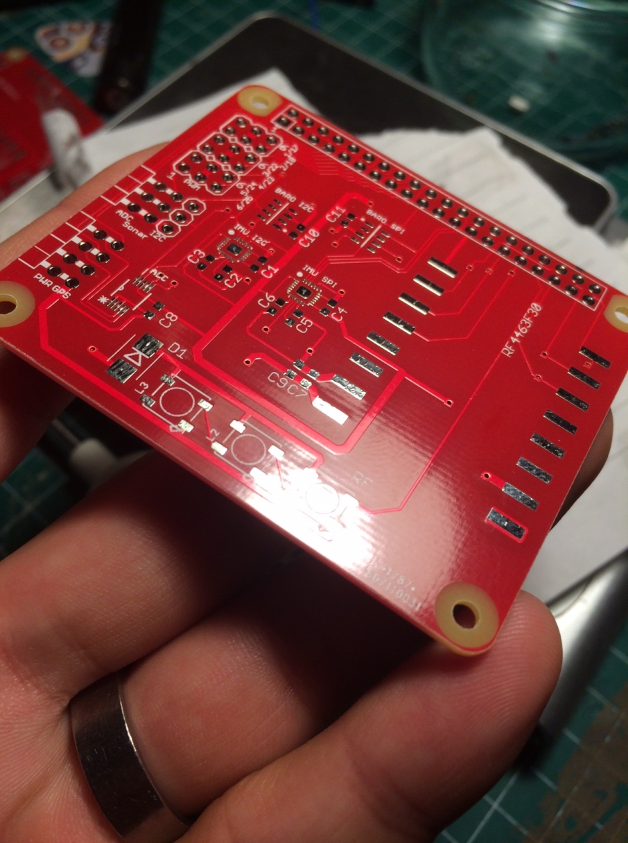
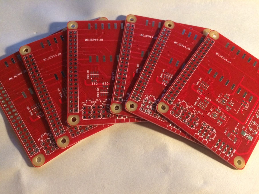
I started working on a custom FC board for silkopter and soon I will receive the first PCBs.

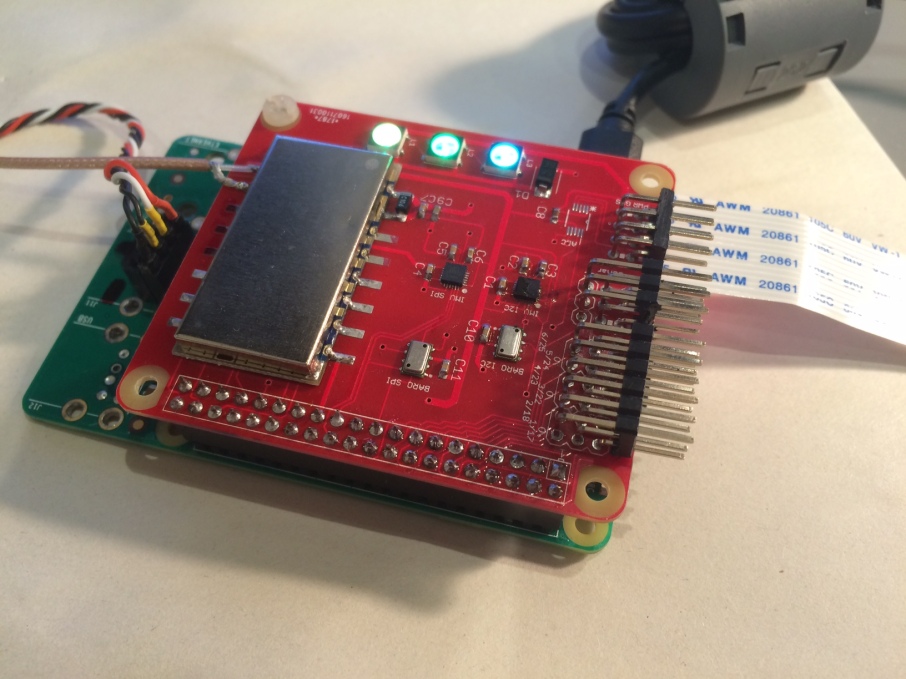
It's meant to be used as a Raspberry PI HAT and all the software (silkopter) runs on raspbian.

The board is 2 layout and can be printed (I hope, still didn't receive them yet) using DirtyPCB for ~30e for 10 boards. It was developed with the free version of eagle (hence the 2 layer limitation) in the past week.

Eagle schematic and PCB layout are on github 

My goal with this board is to have solid, long range RF integrated into the board, add sensor redundancy and experiment with SMD as a side quest.
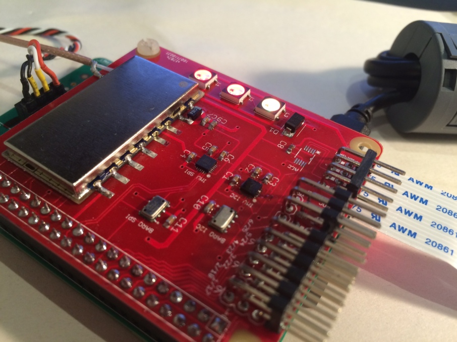
Sensors:

- Dual MPU9250 9-axis IMU, one on SPI and one on I2C. They will both perform @1Khz

- Dual MS5611 barometer, one on SPI and the other on I2C @100Hz for both

- ADS1115 16bit ADC for current/voltage sensing

- Input for a serial GPS like any ublox (3.3V signal)

- Input for a serial sonar like MaxSonar. Works both with UART and RS232 signals (normal or inverted, 3.3V both)

RF:

- Either a RF4463F30 board (-126dBm sensitivity, 1000kbps, 30dBm power)

- Or a RFM22B board (-126dBm sensitivity, 256kbps, ~20dBm power)

Outputs:

- 6 PWM. I plan 4 motors and 2 for gimbal

- 3 RGB leds (NeoPixels or WS2812b)

A skilled developer could adapt Arducopter to support this board in 1-2 weeks. The trickier part would be the RC part to make it use the RF board instead of a classic RC receiver.

I'm also developing a custom RC system with a Raspberry PI, a touchscreen for FPV digital video (800x480 resolution, 2000kbps), a 3 axis gimbal for yaw/pitch/roll and a motorized slider for thrust control.

I'm working now on the component selection and schematic.

The build log is  here.

Feedback is welcome, it's my second PCB ever and my first one with SMD and especially a QFN package.

Read more…

Silkopter - creating a FC in 8 minutes

I've been working on silkopter FC for almost an year and this is the 3rd iteration. The core idea is to model a multirotor as a signal processing device that takes sensor input streams and a RC stream and outputs a PWM stream.

Each processing unit is modeled as a node with zero or more inputs and output streams, each with its own sample rate.

More details here:
https://jeanleflambeur.wordpress.com/

Read more…