Patrick Poirier's Posts (9)

Sort by

jnIcA3G8M0jyU9jvhvkSxOk1acsBJKWox_OyAhGxwRbQWbxAEG2sLuEnOIk_YmKK0Bj1EX38P177JGRC1rJ18Dut9aDmmZ-As_xx1yKWLKgLauTvRpqBjfuv9JVBu6eFZ1P3_avI (1289×720)

As part of a Google Summer Of Code (GSOC). I have the privilege to Mentor a talented PhD Student of the Nanyang Technological University of Singapore, named Thien Nguyen.

Since the beginning of this project , Thien has delivered a series of Labs to serve not only as milestones for the project but also a step-by-step guideline for anyone who wishes to learn about using the power of computer vision for autonomous robot to follow. The labs include:

  1. Lab 1: Indoor non-GPS flight using AprilTags (ROS 2-based)
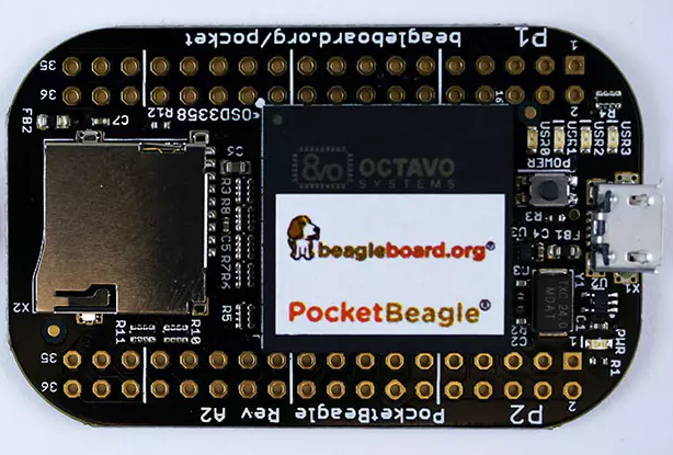
  2. Lab 2: Getting started with the Intel Realsense T265 on Rasberry Pi using librealsense and ROS
  3. Lab 3: Indoor non-GPS flight using Intel T265 (ROS-based)
  4. Lab 4: Autonomous indoor non-GPS flight using Intel T265 (ROS-based).
  5. Lab 5: MAVLink bridge between Intel T265 and ArduPilot (non-ROS).
  6. Lab 6: Calibration and camera orientation for vision positioning with Intel T265.

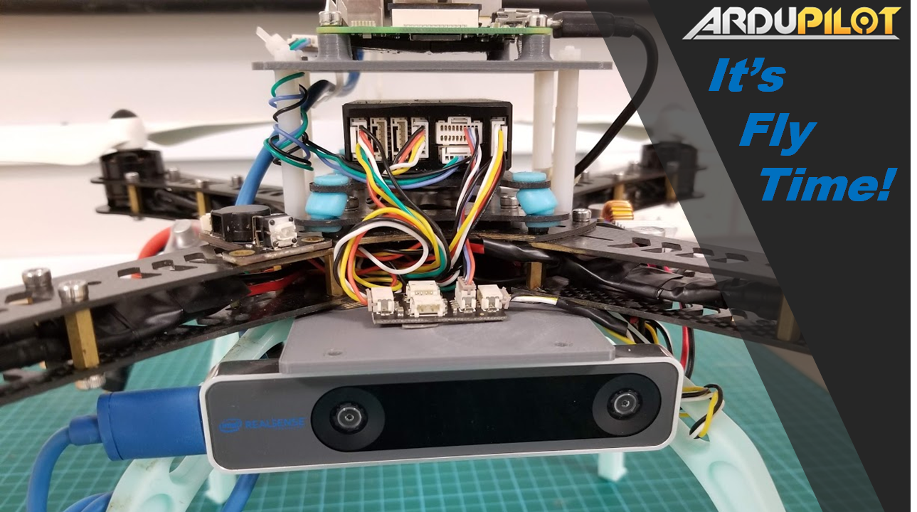
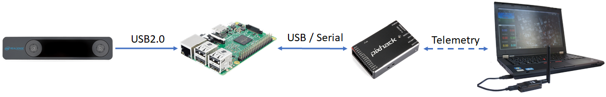
I invite you to read about this series of well detailed  experimentations and  instructions on how you can implement the  RealSense T265 tracking camera system :

https://discuss.ardupilot.org/t/gsoc-2019-integration-of-ardupilot-and-vio-tracking-camera-for-gps-less-localization-and-navigation/42394

Here is a video showing autonomous indoor flight using the system in ROS-Mavros environment  (this is part of Lab 4):

Lab 5 shows how to fly using a Python Scrit sending MavLink Message Vision_Position_Estimate directly to Flight Controller.

ymaV7i3iFv6rqoejJzsXfmAd-QnZRU9XPfQl5wp0IKQUyaVVZFvSS0AWF5y7vP1Klup7cSEpNBo1bs_02FAAt7dfNVAWq4APUo4ld1MYajCWAnRD1eeLkE12SRdRccKR3s8gaGH9

You can read the underlying principles of how to incorporate a VIO tracking camera with ArduPilot using Python and without ROS. After installing necessary packages, configuring FCU params, the vehicle can integrate the tracking data and perform precise navigation in GPS-less environment. Pose confidence level is also available for viewing directly on GCS to quickly analyse the performance of the tracking camera.

Thanks to Thien for this amazing project, experiments can now be carried on the T265 with different Flight Controllers and stacks compatible with the Vision_Position_Estimate  MavLink Message.

Read more…

image.png?width=750

Ahhh... Winter in Canada ...
While the kids play hockey outside with sticks and a puck , I play inside with sticks and a POC !!


A few month ago I started experimenting with the Avoidance Library:
http://ardupilot.org/dev/docs/code-overview-object-avoidance.html

And I designed The POC : Proximity Obstacle Collision avoidance system based on an Arduino Pro Mini and VL50LX0 TOF rangefinders. This unit works pretty well, the only drawback is that it is shortsighted. This inexpensive Laser device is limited to a range of 1,7 Meter and it makes it hard to implement a fully functional Avoidance System.

17cb06ec-0d57-11e7-8245-d0cd93f2208d.png?width=750

Then came the Benewake TFMINI RangeFinder, that offers indoor range up to 12 Meter (6M Outdoor) for a price that makes the POC concept a reality. Some of you might have seen a previous Blog explaining how to make this RangeFinder talk I2C with the use of an Arduino:
https://discuss.ardupilot.org/t/how-to-make-the-tfmini-rangefinder-talk-i2c/24403


Configuration of the TFMINI-POC:
The actual prototype is using 4 TFMINI
One looking UP
3 Looking @ -45 Forward + 45
TFMINI are Serial devices and its quite difficult to multiplex serial without buffering.
I did some test with a Teensy 3.5 that offers 6 serial ports, but without handshake (hardware or software) its is quite difficult to have a stable unit, that can work in a variety of configuration and speeds (baudrate).

This is why I opted to ''transform'' the TFMINI into a I2C device. With the Use of Attiny85 we can read the serial flow @ 115200 and do all sorts of signal manipulation and store results in registers, ready to be consumed by the I2C bus. The controler is an Arduino Pro Mini that sequentially read the I2C devices and transmits over serial on a MavLink DISTANCE SENSOR message http://mavlink.org/messages/common#DISTANCE_SENSOR

image.png?width=750

ARDUINO CODE

You can download the code here:
https://github.com/patrickpoirier51/TFMINI-POC

To make a system set the I2C address for each ATtiny and you assign the corresponding vector to the I2C Address:
https://github.com/patrickpoirier51/TFMINI-POC/blob/master/TFMINI_I2C_MAVLINK/TFMINI_I2C_MAVLINK.ino#L147

SETTINGS
On Mission Planner you set Proximity and Avoidance (as per Avoidnce wiki above) and you can set the avoidance enabling using a transmitter switch, I used ch7 = 40 for Object Avoidance.

And this is how it goes in Alt-Hold Mode:
I use the transmitter to ''push'' the quad against the garage door and the avoidance system makes it ''bounce'' back. The harder we push , the harder it bounce back... just like a hockey puck....


I would like to thanks the development team and more specifically Randy Mackay for this excellent library that makes me play like a kid in these cold winter days ;-)

Read more…

image.png?width=750

**There is a new puppy in the family !!**

**PocketPilot** is a smaller versions of the BBBmini (https://github.com/mirkix/BBBMINI), designed for use with PocketBeagle (https://beagleboard.org/pocket, a small version of BeagleBone Black). It provides a very small & light-weight open-source ArduPilot based autopilot / flight controller for quadcopter drones & robots.

image.png?width=750

**Summary of Technical Specifications**
Processor: Octavo Systems OSD3358 1GHz ARM® Cortex-A8
512MB DDR3 RAM integrated
Integrated power management
2×32-bit 200-MHz programmable real-time units (PRUs)
ARM Cortex-M3
72 expansion pin headers with power and battery I/Os, high-speed USB, 8 analog inputs, 44 digital I/Os and numerous digital interface peripherals
microUSB host/client and microSD connectors

image.png?width=750

For test and initial developments, I have build a prototype using through-hole components & connectors, with sensor modules soldered directly on the breadboard. Since it doesn't need any SMD components, this is relatively easy to build, for an experienced builder by following this schematic:

image.png?width=750


Please note that there is no ESD protection for USB1 on the prototype, so be very carefull if you plan to use it. We will implement proper protection on a PCB release.


The initial flight test was performed on a 450 class quadcopter == Youtube video
Please note this is flying indoor using optical flow (Lidar Lite V3 and PX4FLOW)

**Integration on a 180 size quadcopter**

In order to reflect the compactness of the PocketPilot , I have integrated the prototype into a KingKong 188 (Aliexpress) quadcopter with these components:
4 x Multistar 1704 and DYS20 A ESC (Blheli)
5 Amp UBEC
Micro Flysky PPM receiver
900 Mhz Telemetry radio with Pigtail Spring Antenna
3S Battery 1800 MAh
VL53LX0 TOF RangeFinder

There is no special instructions for the build but you need a good UBEC with a steep voltage rising curve in order to get the PocketBeagle starting becauses of the power/battery management unit.

This is one of the first test on the KingKong, its flying Alt-Hold using the 7$ VlL53L0X TOF RangeFinder

**LINUX and SOFTWARE**
A special thanks to **Mirko Denecke** for having adapted the BBBMINI ArduPilot code to the PocketPilot and **Robert C Nelson** for making the OS Images including: Linux Debian, Kernel with RT patch and the uboot overlays; allowing to define the IO using a configuration file, making the BeagleBone such a powerfull Linux Embedded Computer.

You can read the instructions here:

https://github.com/PocketPilot/PocketPilot/blob/master/PocketInstructions.md

**MORE TO COME:**

For anyone interested, we are planning to release a complete sensor cape for the PocketBeagle so stay tuned :slight_smile:

Read more…

Future of On-Demand Urban Air Transportation

3689703290?profile=original

On-demand aviation has the potential to radically improve urban mobility, giving people back time lost in their daily commutes. Uber is close to the commute pain that citizens in cities around the world feel. We view helping to solve this problem as core to our mission and our commitment to our rider base. Just as skyscrapers allowed cities to use limited land more efficiently, urban air transportation will use three-dimensional airspace to alleviate transportation congestion on the ground. A network of small, electric aircraft that take off and land vertically (called VTOL aircraft for Vertical Take-off and Landing), will enable rapid, reliable transportation between suburbs and cities and, ultimately, within cities.

Read the full text here:   https://medium.com/@UberPubPolicy/fast-forwarding-to-a-future-of-on-demand-urban-air-transportation-f6ad36950ffa#.gkptt7fho

Read more…

One of the world’s first automated inspections by an intelligent drone with deep learning capabilities was demonstrated at the GPU Technology Conference Europe today by Aerialtronics, a Dutch manufacturer of technologically advanced drones, Neurala, a pioneer in deep learning software, and NVIDIA®, the world leader in GPU-accelerated computing.

This new “intelligent drone” identifies objects and their condition in flight, which dramatically increases the efficiency and accuracy of documenting assets, lowering costs, and making it easier for frequent inspections. It adds to the use of commercial drones to help businesses access difficult and dangerous areas, such as cell towers and turbines.

Aerialtronics and Neurala collaborated to make the demonstration on the Altura Zenith UAS, which incorporates the NVIDIA Jetson™ TX1 module. The resulting system can visually inspect a cell tower and recognize the equipment mounted on the mast. This is the first step required to start automating the documentation of assets, and assessing the mechanical functionality and condition of the cell tower to identify rust and other defects..

The real-time processing of the data stream is made possible by combining Aerialtronics unmanned aerial system and their smart dual camera payload with Neurala’s deep learning neural network software, which is capable of finding and recognizing objects in flight, using the NVIDIA Jetson TX1 platform.

“The Jetson platform features high-performance, low-energy computing for deep learning and computer vision, making it ideal for products such as drones,” said Serge Palaric, vice president of EMEAI sales and marketing of embedded and OEM at NVIDIA. “These drones can handle complex or dangerous tasks without risking human life, which is game changing for many industries.”

source: http://www.aerialtronics.com/2016/09/ai-powered-drone-inspections-unveiled-aerialtronics-neurala-nvidia/

Read more…

Source:  https://www.qualcomm.com/news/onq/2016/09/06/paving-path-5g-optimizing-commercial-lte-networks-drone-communication

As a leader in 4G LTE technology, Qualcomm and its engineers did not hesitate to jump at the opportunity to test LTE-controlled drones in real-world scenarios. We were eager to analyze how, and if drones could operate safely and securely on today’s commercial 4G LTE networks.

Today’s cellular networks are designed to serve smartphones and other ground mobile devices, so the first thing we wanted to find was how cellular networks can serve drones which operate at higher altitudes. Conventional wisdom says that current cellular deployments can’t provide coverage for drones at higher altitudes because antennas on cell towers point down to serve mobile devices on the ground.

We also wanted to study how to support safe drone operation in real-world environments without impacting terrestrial network operation. Our findings from this research would not only help us optimize LTE networks for safe drone operation, but also inform positive developments in drone regulations and 5G specifications as they relate to wide-scale deployment of numerous drone use cases.

To begin, Qualcomm Technologies worked with the U.S. Federal Aviation Administration (FAA) on a certification of authorization allowing for drone testing below 400 feet around the company’s San Diego headquarters. Our FAA-authorized Unmanned Aerial Systems (UAS) Flight Center not only provided ideal proximity to extensive Qualcomm R&D facilities, but it also allowed for testing inside Class B Controlled airspace because of its location near Marine Corps Air Station (MCAS) Miramar — a very active military air station. In addition, our flight center is surrounded by the very real-world conditions autonomous drones must one day navigate, including commercial zones, populated residential areas and large swaths of uninhabited areas. Combined, these areas make our flight center’s location one of the most challenging real-world testing environments possible.

Read more…

Combined with Intel’s Existing Assets, Movidius Technology – for New Devices Like Drones, Robots, Virtual Reality Headsets and More – Positions Intel to Lead in Providing Computer Vision and Deep Learning Solutions from the Device to the Cloud

Computer vision is a critical technology for smart, connected devices of the future. (Credit: Intel Corporation)

Source:https://newsroom.intel.com/editorials/josh-walden-intel-editorial/

With the introduction of RealSense™ depth-sensing cameras, Intel brought groundbreaking technology that allowed devices to “see” the world in three dimensions. To amplify this paradigm shift, they completed several acquisitions in machine learning, deep learning andcognitive computing to build a suite of capabilities that open an entirely new world of possibilities: from recognizing objects, to understanding scenes; from authentication to tracking and navigating. This said, as devices become smarter and more distributed specific System on a Chip (SoC) attributes will be paramount to giving human-like sight to the 50 billion connected devices that are projected by 2020.

With Movidius, Intel gains low-power, high-performance SoC platforms for accelerating computer vision applications. Additionally, this acquisition brings algorithms tuned for deep learning, depth processing, navigation and mapping, and natural interactions, as well as broad expertise in embedded computer vision and machine intelligence. Movidius’ technology optimizes, enhances and brings RealSense™ capabilities to fruition.

We see massive potential for Movidius to accelerate our initiatives in new and emerging technologies. The ability to track, navigate, map and recognize both scenes and objects using Movidius’ low-power and high-performance SoCs opens opportunities in areas where heat, battery life and form factors are key. Specifically, we will look to deploy the technology across our efforts in augmented, virtual and merged reality (AR/VR/MR), drones, robotics, digital security cameras and beyond. Movidius’ market-leading family of computer vision SoCs complements Intel’s RealSense™ offerings in addition to our broader IP and product roadmap.

Computer vision will trigger a Cambrian explosion of compute, with Intel at the forefront of this new wave of computing, enabled by RealSense™ in conjunction with Movidius and our full suite of perceptual computing technologies.

Read more…

I finally received my Raspberry Pi Zero,  just in time to get into the DIY challenge of building a smart drone with the Pi Zero and APM under 100$. I called this project: MINI-Zee

3689684951?profile=original

How this can be done?

Well first of all, thanks to Victor and the team at Erle Robotics for releasing the plans and software of their PXFmini.  This is a real inspiration for building my own board, because all the parts are available at a cheap price and are relatively easy to assemble and interconnect using through-hole breadboard, providing you are very experienced with this type of build.  Thanks to Mirko as well, for having introduced a real DIY autopilot project that allows us to experiment with a fully working and well supported BeagleBone  based  ArduPilot  Cape called the BBBMINI.


3689684972?profile=original

Bill of Material (US$ - Transport & taxes excl.):

Raspberry Pi Zero                                      5.

MPU 9250 (SPI 9 dof IMU)                         8.

MS 5611 (SPI Baro)                                   9.

PCA 9685 (16 channel PWM Servo Driver)  5. 

3.3 v. regulator                                          1.

BEC 3 amps                                             3.

Breadboard, Resistors, Connectors, Misc.   7.

                                               AutoPilot:  38.

HobbyKing Spec FPV250 V2 Quad Copter

ARF Combo Kit - Mini Sized FPV         60. 

                                                     Total:  98.

*This is Banggood price; I had an ADAFRUIT –PWM on hand, and I really recommend going with ADAFRUIT, because of all the effort  they put on making a great tutorial and drivers for this product. Note: Just like Erle , the USB WIFI, GPS and the Radio Control are excluded.

Building:


A) Hardest part: Get a  RASPBERRY PI ZERO (Where is my Zero site)
B) Hardware - See BOM
C) Board Schematics : Erle pxfmini
D) Board Software: Erle pxfmini

E) LOAD LATEST Raspbian-Jessie

Disable serial Login (Allow GPS on serial Port)
Enable , I2C, SPI , Serial
Disable Console = Auto Log on a shell


F) LOAD RT-PREEMPT
http://www.frank-durr.de/?p=203
Load Test Result: TEST: T: 0 ( 1136) P:80 I:500 C: 100000 Min: 16 Act: 31 Avg: 32 Max: 157


G) MAKE ArduCopter

Special MINI-ZEE release:
1) The MPU 9250 is mounted on the Z-Axis, so we need to change : 

CONFIG_HAL_BOARD_SUBTYPE == HAL_BOARD_SUBTYPE_LINUX_PXFMINI
, _default_rotation(ROTATION_YAW_270)  = to ROTATION_NONE

2) The PCA9585 has no external clock, and the ESC are connected to ports 1-2-3-4, so we need to change: 

static RCOutput_PCA9685 rcoutDriver(PCA9685_PRIMARY_ADDRESS, true, 3, RPI_GPIO_27);      -to-

static RCOutput_PCA9685 rcoutDriver(PCA9685_PRIMARY_ADDRESS, false, 0, RPI_GPIO_27);

H) Fly the MINI-ZEE == Add these to /etc/rc.local

#wait till network is up and DHCP assigned address

while ! ifconfig | grep 192.168.2. >> /home/pi/bootlog; do
echo “no network, waiting…” >> /home/pi/bootlog
sleep 5
done
echo “Starting ArduCopter” >> /home/pi/bootlog

sudo /home/pi/ardupilot/ArduCopter/ArduCopter.elf -A udp:192.168.gcu-address:14550  -B /dev/ttyAMA0 > /home/pi/startup_log &

exit 0

I) FIRST FLY LOG:

3689684898?profile=original

Thanks to the damping platform, the vibration level is within specs. Video is available for anyone interested..;-)

Conclusion:

This project took about 20 hours to complete. As you can see, I really enjoyed  doing some hardcore DIY to demonstrate that it is still possible to build your own flight controller from a Linux Based system.  I do not recommend to try this as a first project, but if you are interested, get a BBBMINI, this is the best introduction to DIY  and if you want to fly a Raspberry Pi Zero, it is much  easier to buy a PXFMINI.

Read more…

Take a look under the hood

ADAS , will this be the next generation of autopilot ?


ADAS.jpg


The next step toward fully autonomous  UAV systems is based on acquiring and processing in real-time, information from visual (and/or other spectrums) surrounding space around the vehicle, and  sending  steering commands to the flight control unit so that navigating across an obstructed and ever changing environment without any external intervention might be feasible.


Real-time performance of embedded vision system is  a real challenge, as there is no single hardware architecture that meets perfectly the requirement of each processing level. We can categorise the different processing levels in computer vision as; Low-level processing that is characterized by Millions of repetitive operations on pixels on every seconds; Intermediate-level, is focused on certain regions of interest that meet particular classification of Thousands of objects on every seconds;  and the High-Level on which  object recognition , sensor fusion, decision making and application control are processed at a rate of hundred of operations per second.


At the current state of development, new generations of Systems On Chip - SoC-  that are tightly integrating Arm processors with Programmable Logic are particularly well suited to meet these requirements (1)(2). Multiples camera signals can be processed in parallel and with a very low latency within the programmable logic fabric of these Soc and the Intermediate and High level can be share between the FPGA, DSP, LUT and Arm processors within the chip. High level libraries and tools -like OpenCV- can be synthesized in programmable logic to build a customized accelerator that can be implemented with both higher performance and at much lower power consumption than a similar GPU-CPU model. Other technologies for this type of processing are available.  ASICs are highly integrated chips designed and built for a specific application. They offer high performance and low power consumption but manufacturing cost makes them unaffordable for low volume application. DSPs are very attractive for embedded vision systems, their capacity to do single cycle multiply and accumulation operations, in addition to parallel processing capabilities and integrated memory blocks.


A new generation of DSP, engineered specifically  for Advanced Driver Assistance Systems - ADAS in the automotive industry are now available. These families of SoC incorporate a heterogeneous, scalable architecture that includes a mix of DSP cores, vision accelerators, ARM Cortex-A15 MPCore and dual-Cortex-M4 processors. Texas Instrument and Toshiba have just released their own set of SoCs dedicated to this emerging market(3)(4). As an example, TI TDA2x SoC incorporates a heterogeneous, scalable architecture that includes a mix of fixed and floating-point TMS320C66x digital signal processor (DSP) generation cores, Vision Acceleration Pac, ARM Cortex-A15 MPCore and dual-Cortex-M4 processors. The integration of a video accelerator for decoding multiple video streams over an Ethernet AVB network, along with graphics accelerators for rendering virtual views, enable a 3D viewing experience. And the TDA2x SoC also integrates a host of peripherals including multi-camera interfaces (both parallel and serial) for LVDS-based surround view systems, displays, CAN and Gig Ethernet.


The TI Vision Software Development ToolKit  is complete with more than 200 optimized functions for both Embedded Visual Engine and DSP libraries, providing developers with the building blocks to jump start development and reduce the time to market. Additionally, both libraries are available for low-to-mid- and high-level vision processing. Integral image, gradient, morphological operation and histograms are examples of low-level image processing functionalities; HOG, rBRIEF, ORB, Harris and optical flow are key functions as a mid-level and Kalman filtering  and Adaboost are high-level processing functions.


Future development on these platforms can be implemented with OpenVX framework(5). OpenVX is an open, royalty-free standard for cross platform acceleration of computer vision applications. OpenVX enables performance and power-optimized computer vision processing, especially important in embedded and real-time uses cases such as face, body and gesture tracking, smart video surveillance, advanced driver assistance systems (ADAS), object and scene reconstruction, augmented reality, visual inspection, robotics and more.


So, next time you’ll search for an advanced autopilot to control your UAV, take a look under the hood.


References:

(1)http://www.xilinx.com/products/silicon-devices/soc/zynq-7000/silicon-devices.html

(2)https://www.altera.com/products/soc/portfolio/cyclone-v-soc/overview.html

(3) http://www.ti.com/lit/wp/spry260/spry260.pdf

(4)http://toshiba.semicon-storage.com/ap-en/application/automotive/safety-assist/image-recognition.html

(5) https://www.khronos.org/openvx/


Read more…