Hi all,
Maybe of interest for some of you, the Swiss national TV channel 1 (TSR1) broadcast a short doc on military drones, in french.
Happy watching and cheers
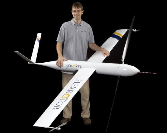
 See demo video hereIf anybody has experienced that airframe, please let us know.
 I had some regular e-mail contact with LocoSys since I bought my 5Hz LS20031 GPS board from Sparkfun.LocoSys informed me that in June or July, they are going to propose an upgrade applicable to the LS20031. The GPS will then be able to have a 10Hz update rate.I'll post more information when available. in the meantime, here's the latest LocoSys product table for those interested: 2009DM.pdf
 While testing my setup, it often disturbed me that the Xbee Pro doesn't have a led somewhere to show it's powered up.Since I mount it onto a ply through an Xbee breakout board like the one on the picture, I just soldered a small red led between the VCC and GND. Now I know when it's powered ok without having to setup all Xbee transmission line.Of course, the led doesn't tell me if the Xbee is transmitting/receiving.
FMA CoPilot thermopile sensor
Soldering breakout cable to dismantled FMA CoPilot
CoPilot with breakout cable
Locosys LS20031 GPS board with 4 pin male header
Plugging GPS board into turret
Adding some foam pad between GPS and CoPilot
Plugging CoPilot and inserting into turret
Turret back view with inserted devices
Turret side view
![]()