Story
About year back, I found OpenLRS. When looked on schematics I discovered it's really simple. I checked local parts supplier and found out 433Mhz and 868Mhz RFM22B modules to be about 9$ Then calculated that price would be half if I do it myself. So I ordered 433Mhz (868 was not in stock) ones and started to copy Flytron's schematic.
In summary there were three reasons for me to do my version
- wanted 868Mhz version as using 433MHz in EU is legal only with low power of 10mW
- price, about 20$ for Rx and 25$ Tx even with board from pool service
- native JR module, no stupid JR<>Futaba converter
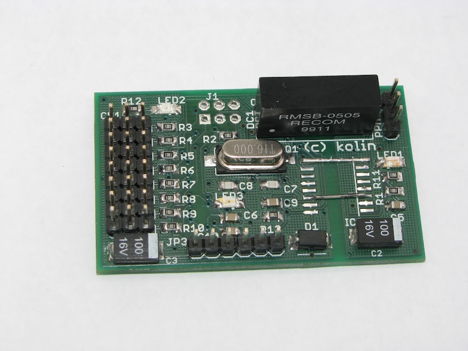
Hardware design
Schematic of receiver is very same as original Flytron's one. I only used bigger 0805 passives, different regulator, added ISP and so. Parts are chosen to be obtainable in local store here in Czech.
Transmitter board was designed for the original FlySky 9x transmitter module case. Just remove original PCB and put this one in case. There is also selectable inverter of input PPM signal to be compatible with JR (was not tested yet). Someone on flytron's forum recommended me to add serial telemetry for 9x as many has done for Frsky modules. So in 1.1 it's there, selectable by solder jumper.
Every component can be bought at TME
Prototype
First batch of one Tx and two RX has been made in end of may 2012. These modules were 433Mhz and there was a bug in Tx module wiring, there were compatible with olrs firmware only after mod. They work well, I flown them for many hours. Never made it public. First version can be seen here https://picasaweb.google.com/m.kolinsky/KolinSRCDev
New revision was finished yesterday. I ordered 868Mhz modules, did simple hack in software and they work!
Software
For the first prototype I used original flytron FW, only changed IO mapping to suit my board.
For second one I started with thUndeadMOD4. Only needed change in software was to load different registry values for base frequency.
Real life tests
With first prototype I was really brave (or stupid) to put this to my greatest, most expensive and most labour intensive plane ever, UltraMaxiSwift (will show it in another blog post) and everything worked well, it has about one hour in the air. Also many hours with Twinstar2 FPV with 2.4GHz/500mW video transmitter.
Second prototype (now 868Mhz) was tested yesterday on RC car. In low power range test mode (1mW output power) range was about 100m before glitches. This was with 1/4 lambda wire antenna. Seems to be OK. Due to weather, real life test to be done.
I checked real output of modules by receiving transmission with popular RTL-SDR. Channels are exactly were they should be. Looks nice
Legality
Here in Czech (and probably rest of EU) authorities allow to transmit 500mW of power with 10% duty cycle in 869.400–869.650 MHz band. Base frequency and hopping channels in my SW are selected to fit in this band. Duty cycle requirement is not fully satisfied, but modules are transmitting only 100mW, so it should be acceptable. Certainly less unlawful than using 433MHz band here.
How to get
If you are interested you can:
- download eagle files, order PCB, parts and do it yourself
- buy Flytron's one and replace RFM22 or write Melih to do it for you
- buy hobbyking's version and replace RFM22
- contact me, I would order more PCB's
Conclusion
I want to thanks Melih from Flytron for great idea of making such simple and effective RC system and for making it opensource.
I probably would not buy new Frsky 2.4Ghz receivers anymore as these are cheap and reliable. With hobbyking's clone of OpenLRS, there will be much more attention for this project.
Download
Here you an download eagle files and modified firmware.kolrs868-fw-hw.zip
P.S. excuse my English ;)