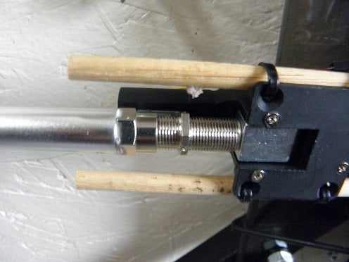
Test run using bamboo skewers to hold the retracts aligned in place

I've been working on this and decided I need to find someone to produce the main plate for mounting of the gimbal and servos, or at least a render file for me to find a fabricator at a reduced price
Unless I can arrange a group order for plates somehow
The design is quite simple and parts are easily found to build one, besides the mounting plate itself
It requires:
2 - Retract servos http://www.hobbyking.com/hobbyking/store/uh_viewItem.asp?idProduct=23483
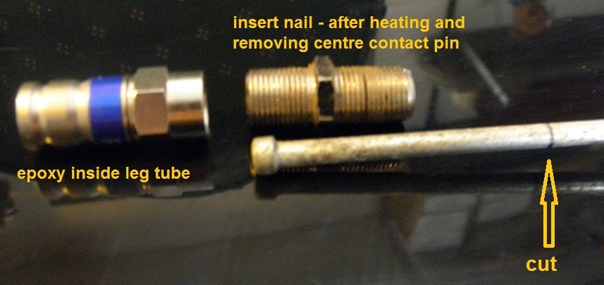
2 - Coax Connectors http://www.ebay.ca/itm/151079759256
2 - Coax Couplers http://www.ebay.ca/itm/321206494080
2 - 4mm diameter nails
2 - 12mm OD x 10mm ID 200mm Long Tubing http://www.ebay.com/itm/111176377084
Epoxy & CA Glue
Tools required involve Something to cut the nail & Tubing to the needed lengths
A hot air gun or something to heat the coupler to melt the inside and remove the centre pin Maybe a hammer or vice, A hacksaw
I started by heating & removing the centre from the couplers and inserted the nail while the coupler was still pliable inside
measured the needed nail after the coupler to replace the stock retract pins and cut the extra off
Made a notch in the nail shaft to match the set screws on the retracts
the tubes only involved epoxying the coax connectors in one end and cutting to the desired lengths
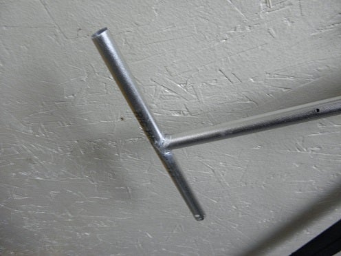
shaping the leg end to join the foot tube to provide a uniform joint with the curve of the foot tube
I used some spare aluminum tail tubes like these as my gear and epoxied them together to form the "T"
26" Double Horse Helicopter Tail Booms http://www.ebay.ca/itm/321102071864
The gimbal I'm using and designed the mounting holes from:
Gimbal Mount http://www.ebay.com/itm/171136254422
Gimbal Motors http://www.ebay.com/itm/121185850081
my idea is to make the top plate rubber anti vibe mount holes in the finished retract and gimbal plate thus the need for the top plate on the original gimbal mount will be omitted and the rubbers would be attached to the new plate instead
Comments
I had to add aluminum plates to provide a stop point for the leg servos
if these changes in the design were done, the retract plate itself would provide the stop itself
Thanks,
I still need a cf version, this one is painted lol
I have to find a good supplier for cf plate still, been busy tho
Assembled with adapters and 16mm tubes
closeup
adapters
A 3D Printed adapter made for a test solution over the aluminum one
another update...
Need to produce some other adapters to suit the larger inner diameter tubes
-
1
-
2
-
3
-
4
-
5
of 5 Next