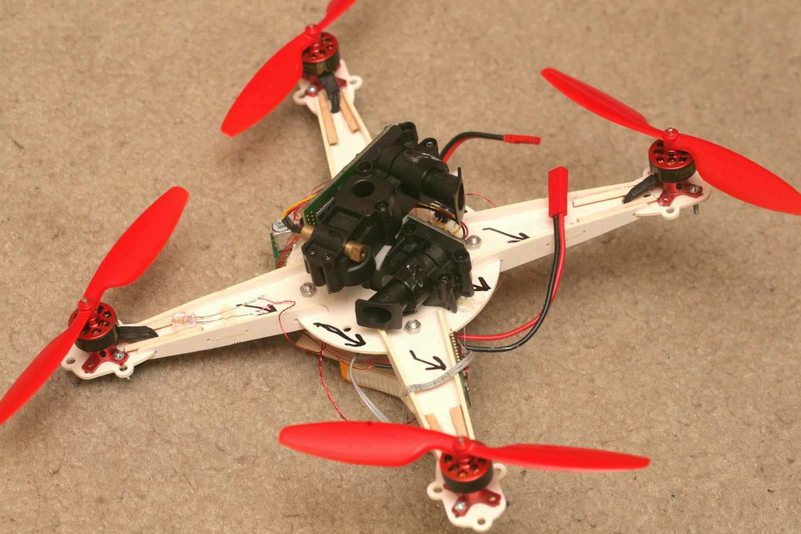

The journey begins with 3 XV-11 lidar modules.

Random bits of information about the XV-11 lidar:
http://xv11hacking.wikispaces.com/
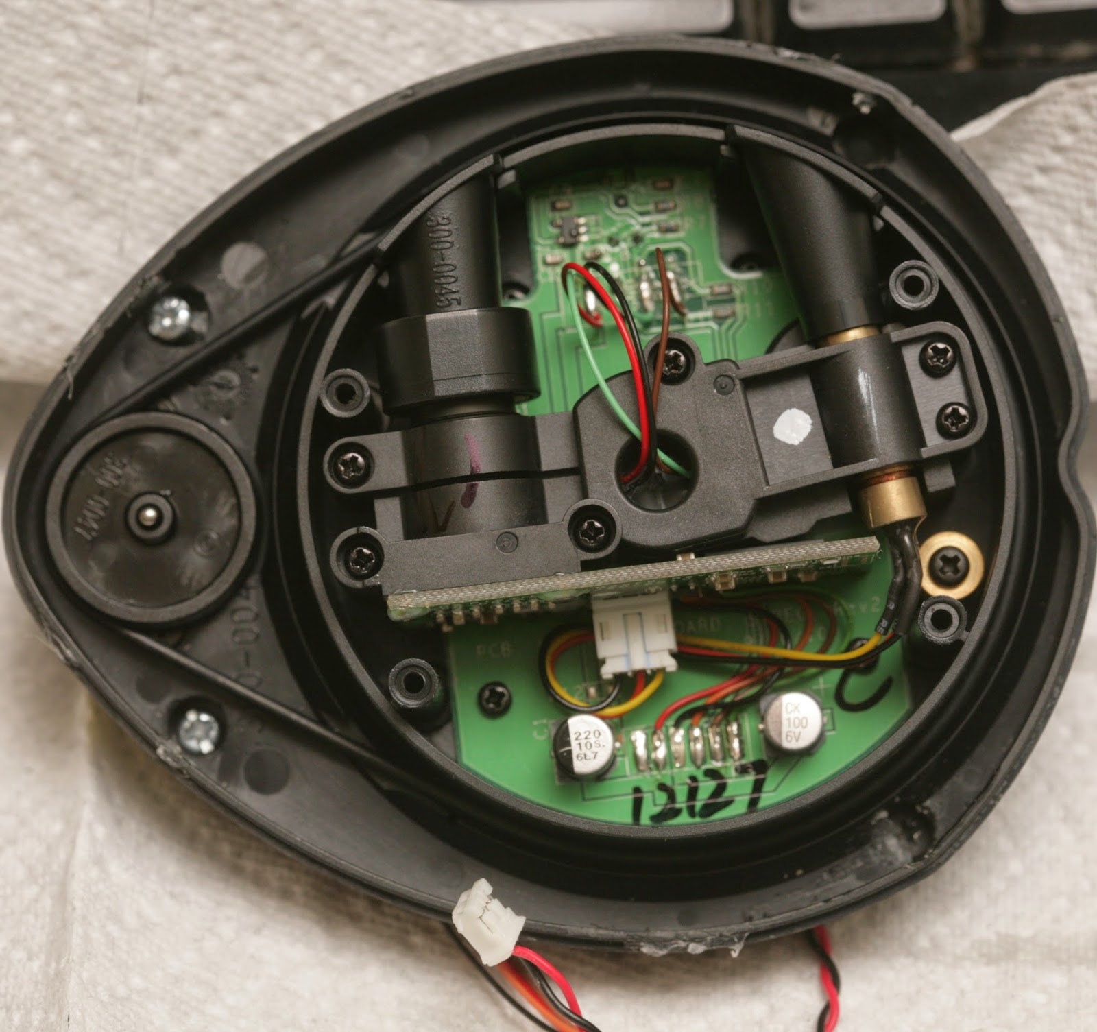
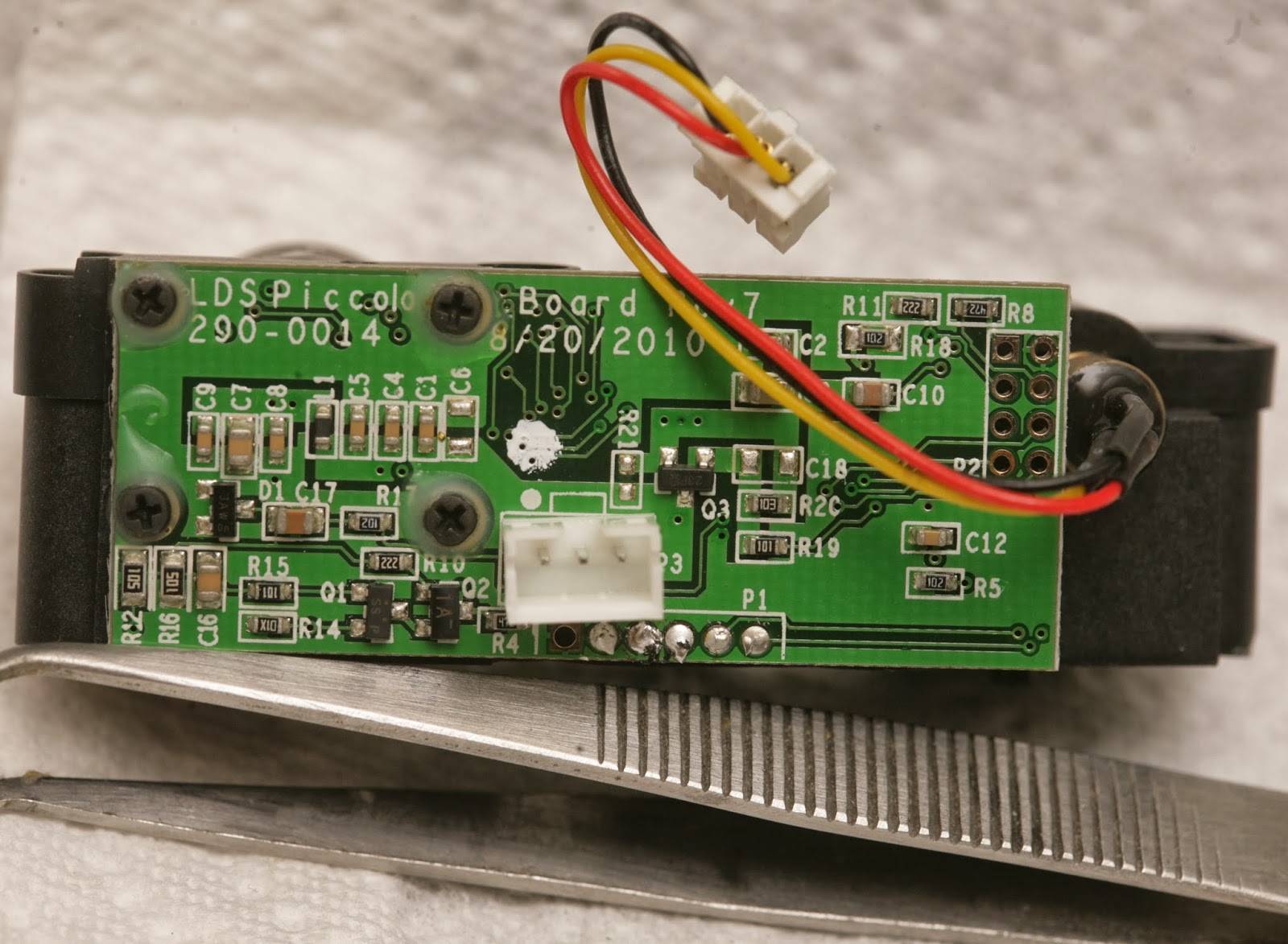
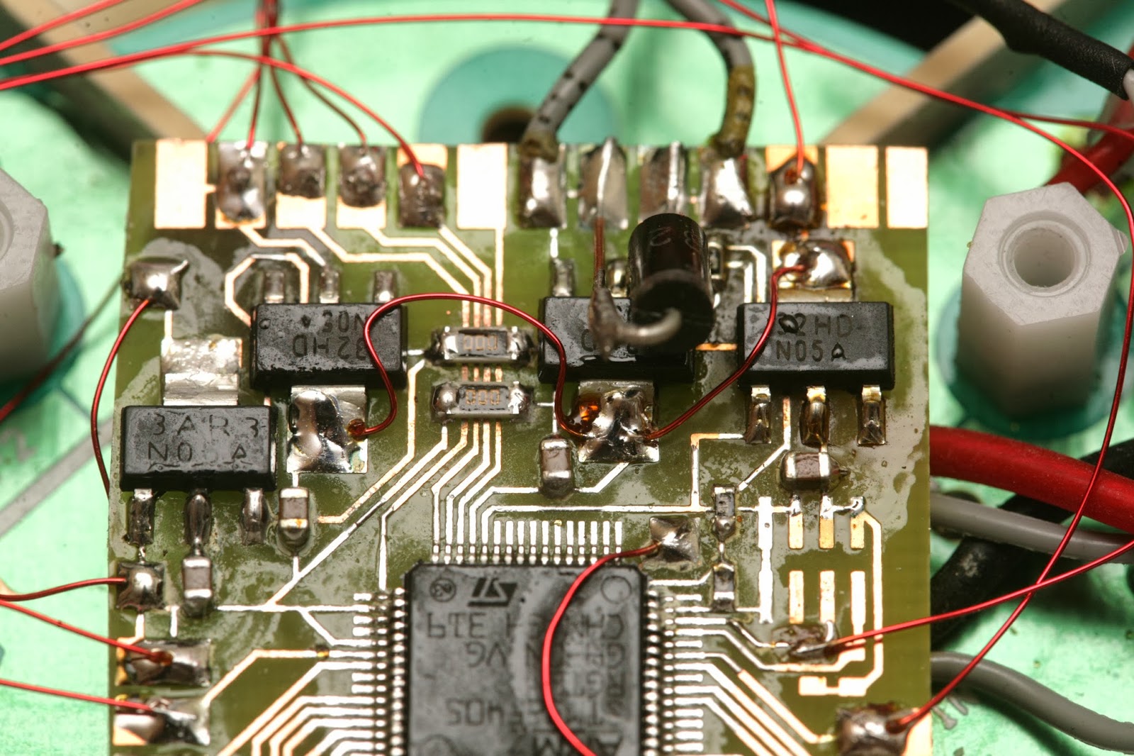
It's definitely a Silicon Valley startup product. There's no emphasis on miniaturization. It's loaded with unnecessary, cosmetic plastic. The PC board is 1/16" thick. It uses 1990's era 0603, 0805 components, full size JST connectors. The laser & camera are giant. It's bare minimum set top box parts repurposed for lidar.
The sensors came from fully assembled vacuum cleaners, since they still had the screws with threadlock.
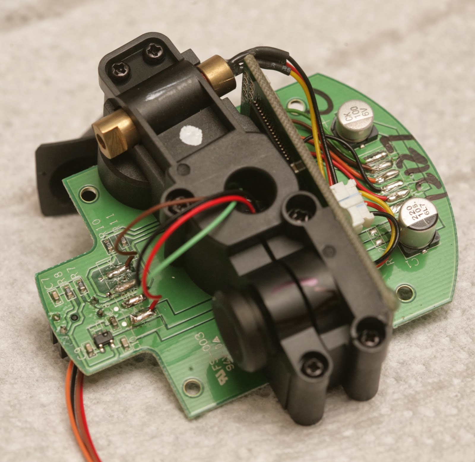
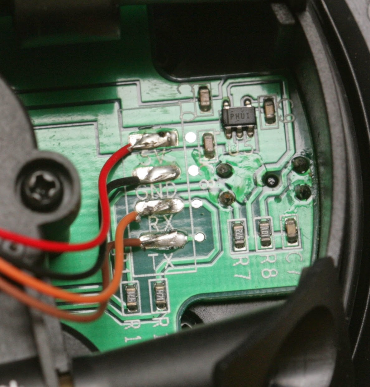
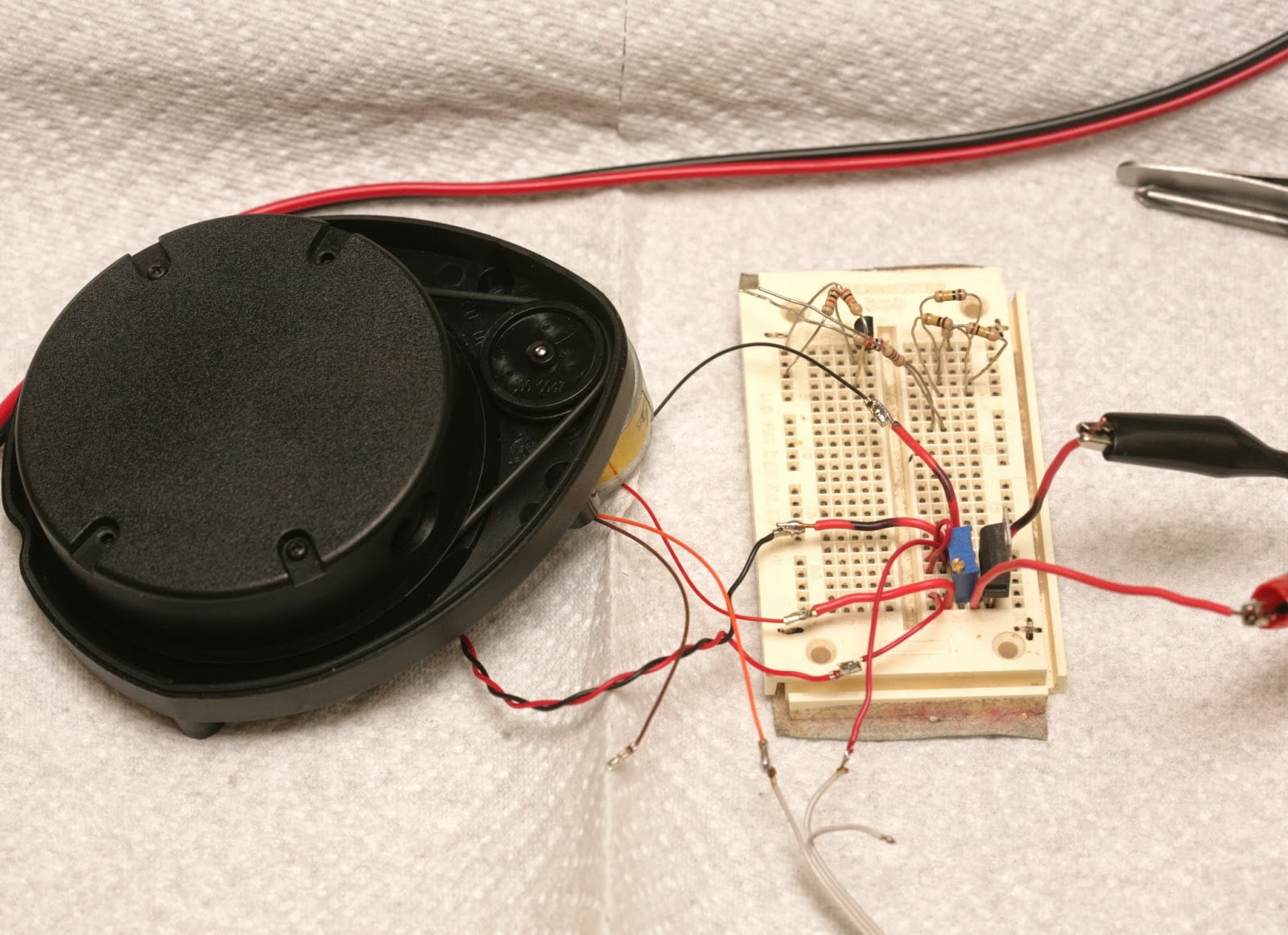
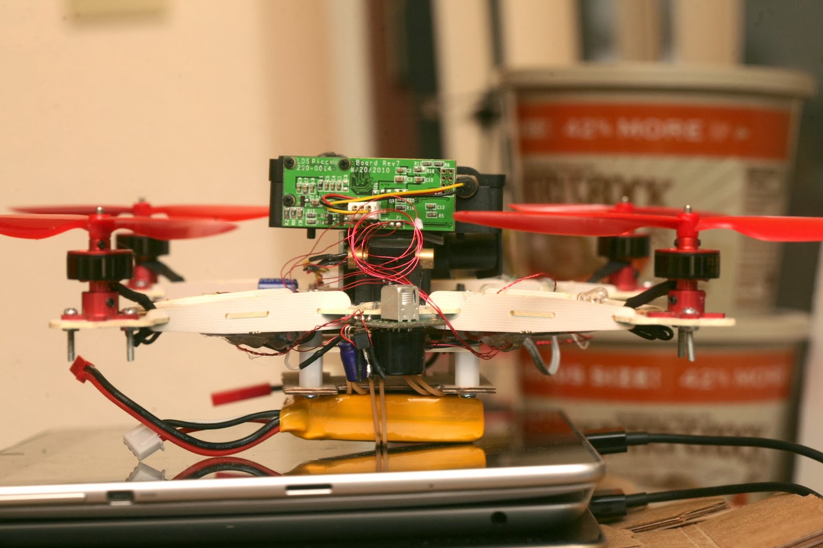
Since it clearly was too heavy to fly in its spinning form, it was time to extract the bare ranging element. The ranging element weighs 30g. The PX4flow weighed 17.5g. The board has 5V labeled, but it's converted to 3.3V by an LDO.
red: 3.3V
black: GND
orange: photodiode output
3.3V when interrupted 0V when clear
brown: TX data going into device
green: RX data going out of device
In true silicon valley H1B worker fashion, the TX & RX labels were reversed. TX on a device normally means signal going out of the device, but the sensor has it meaning signal going into the device.
A 220uF cap filters the 5V power. A 100uF cap filters the 3.3V power. The UART signals have 4.7k resistors.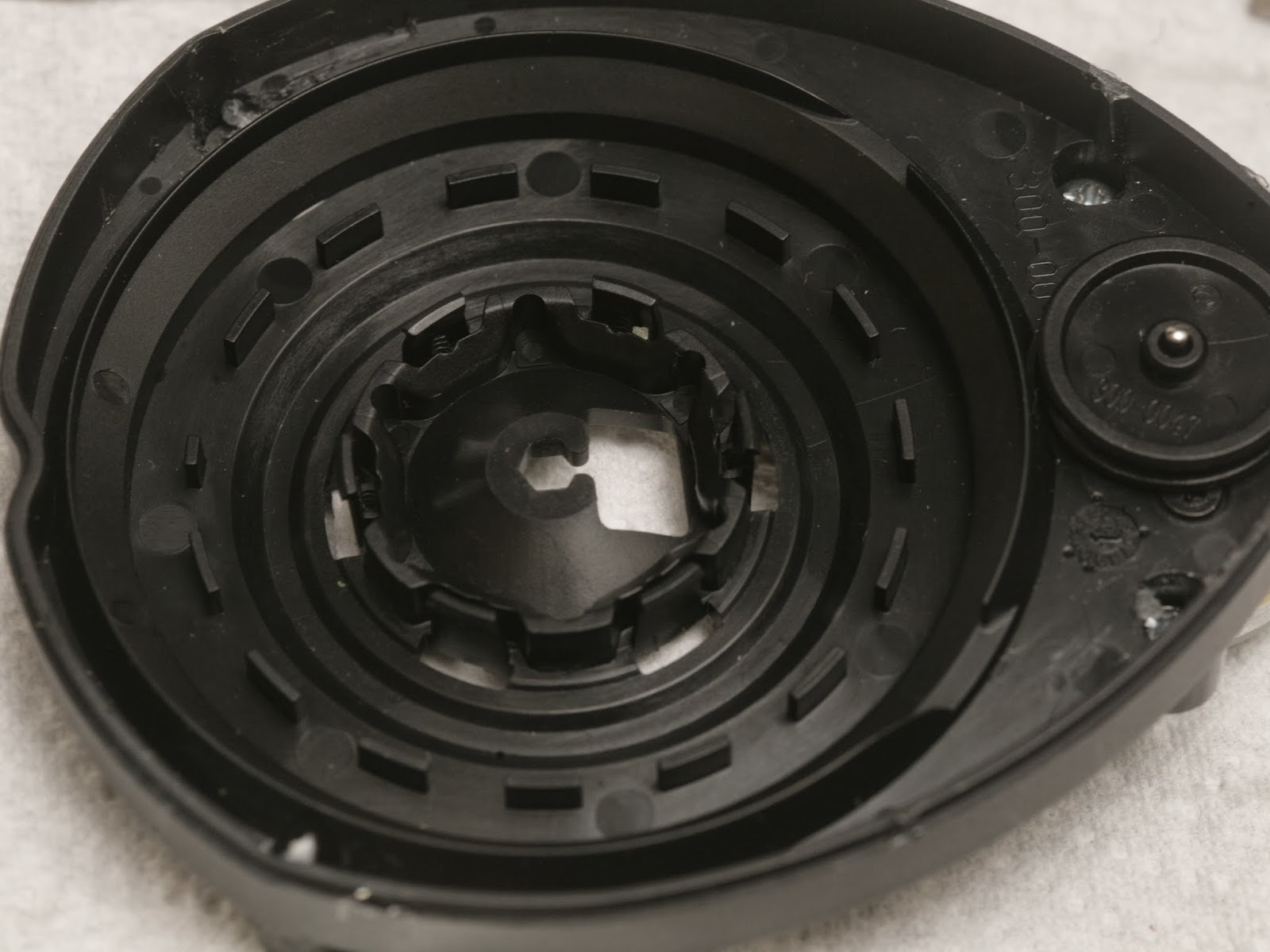
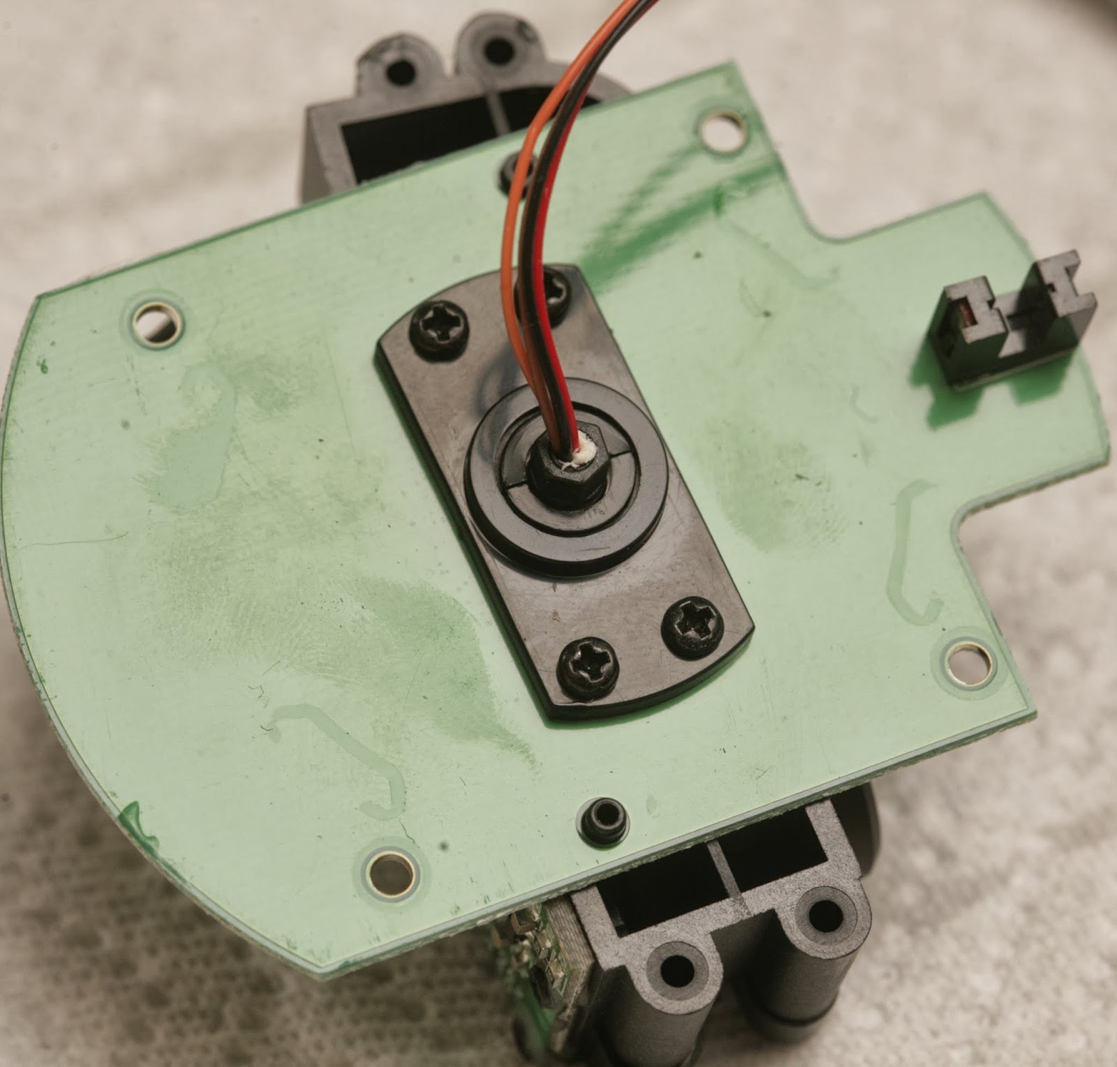
The photo interrupter pattern has 15 interruptions per revolution with a shorter one to tell it where the azimuth is.

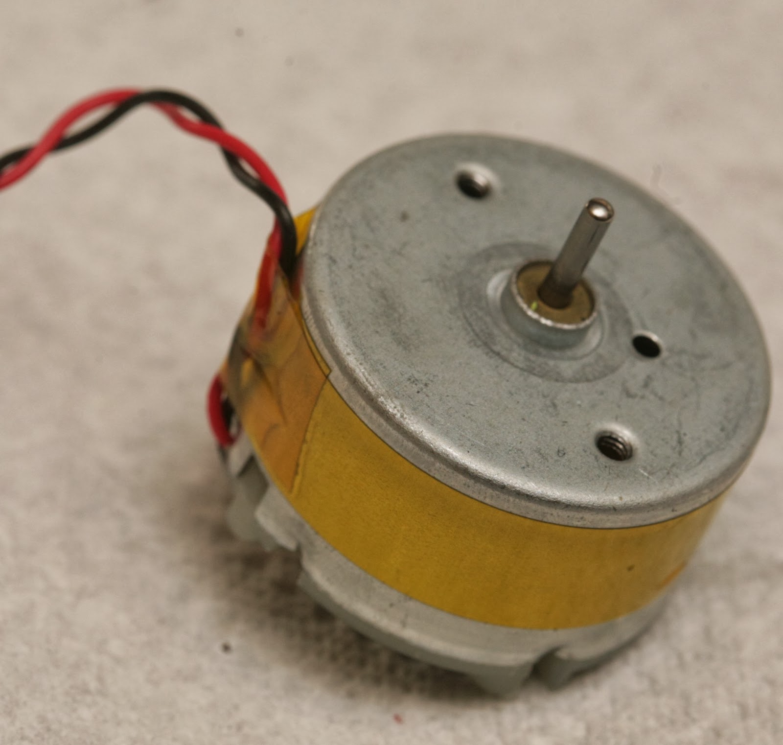
There's a decent quality bearing & brushed motor.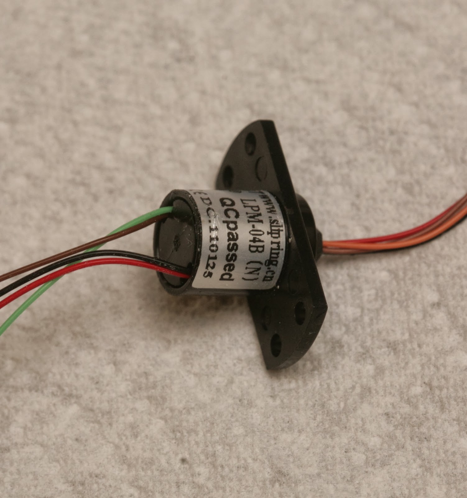
The slip ring would be very useful if you're into synthetic aperture radar & have a way to drill perfectly aligned holes.
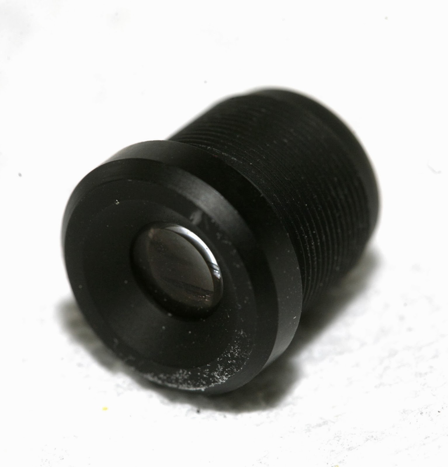
The lens is variable focus with 1 screw clamping it down. Once unscrewed, it becomes lose. There's no way to focus it without an unknown debugging mode.
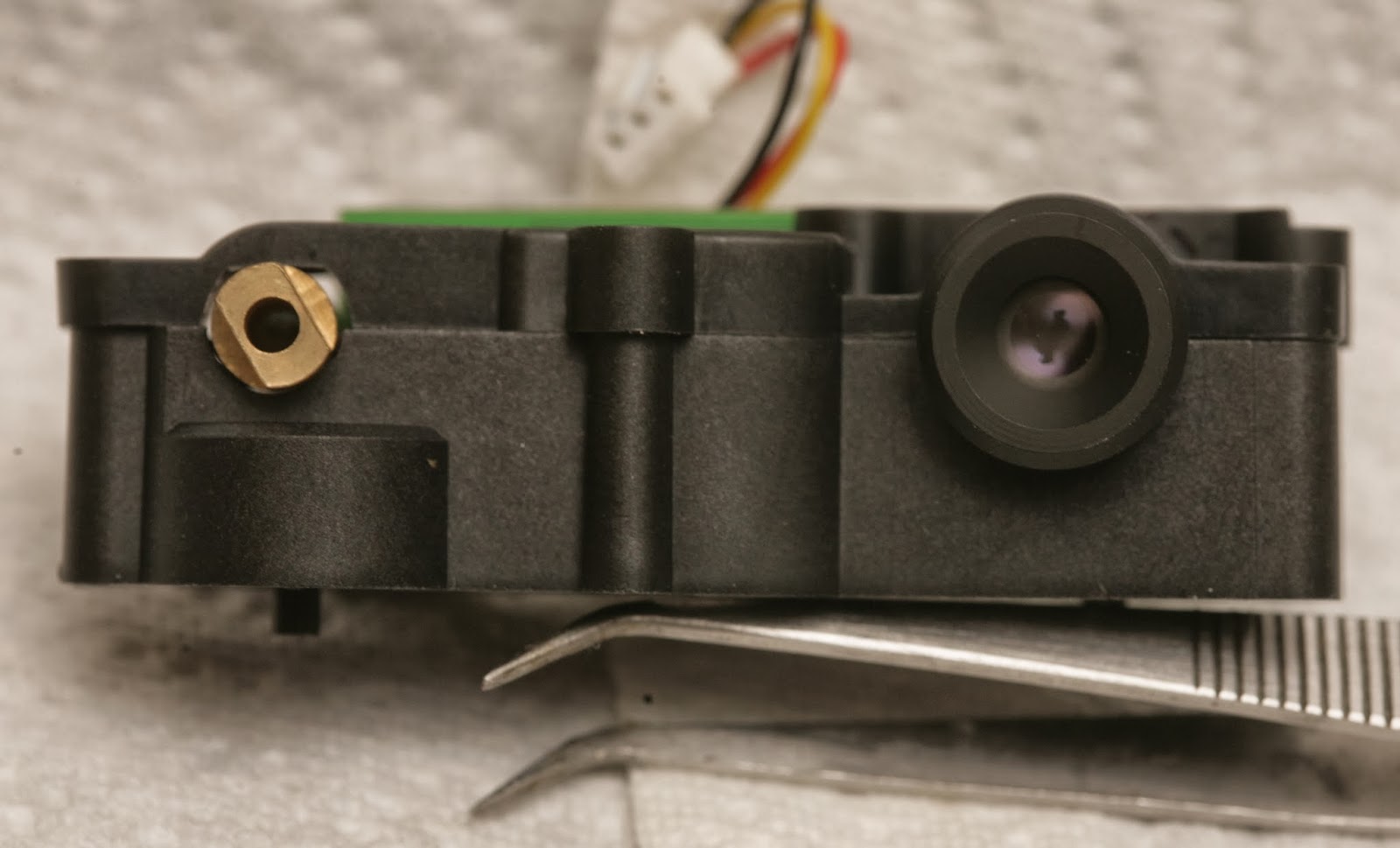
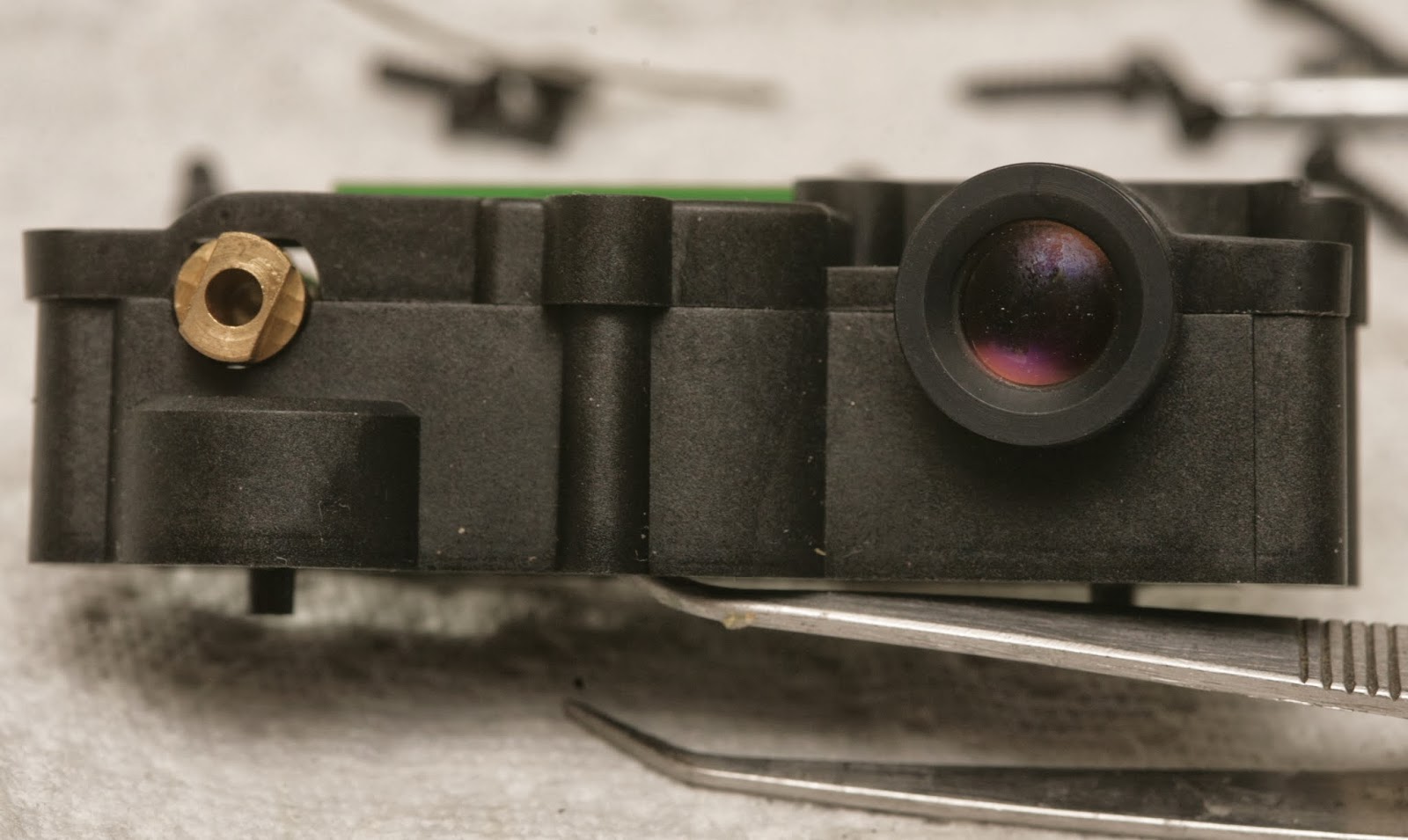
2 of the modules had smaller lenses. 1 had a larger lens.
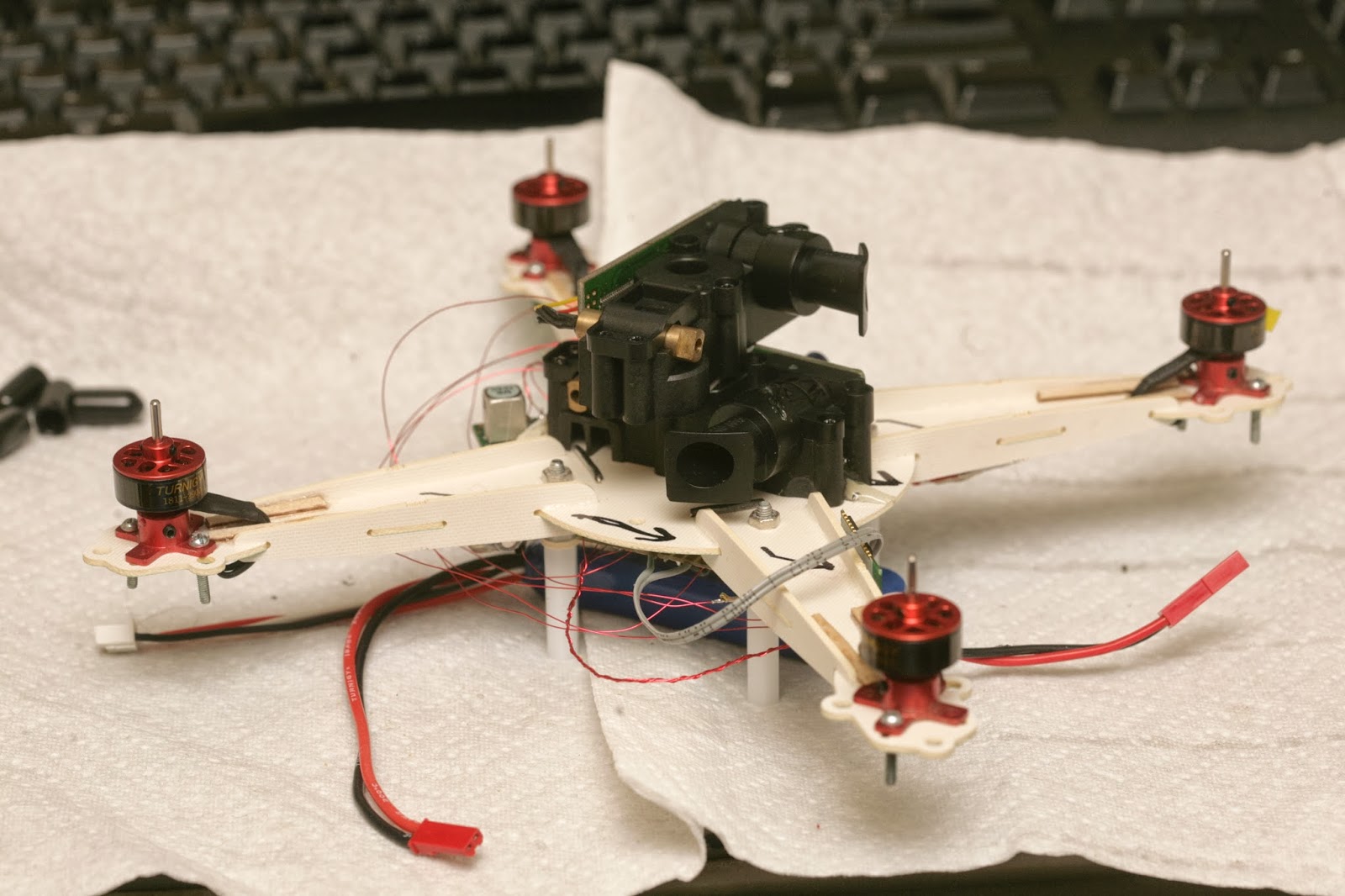
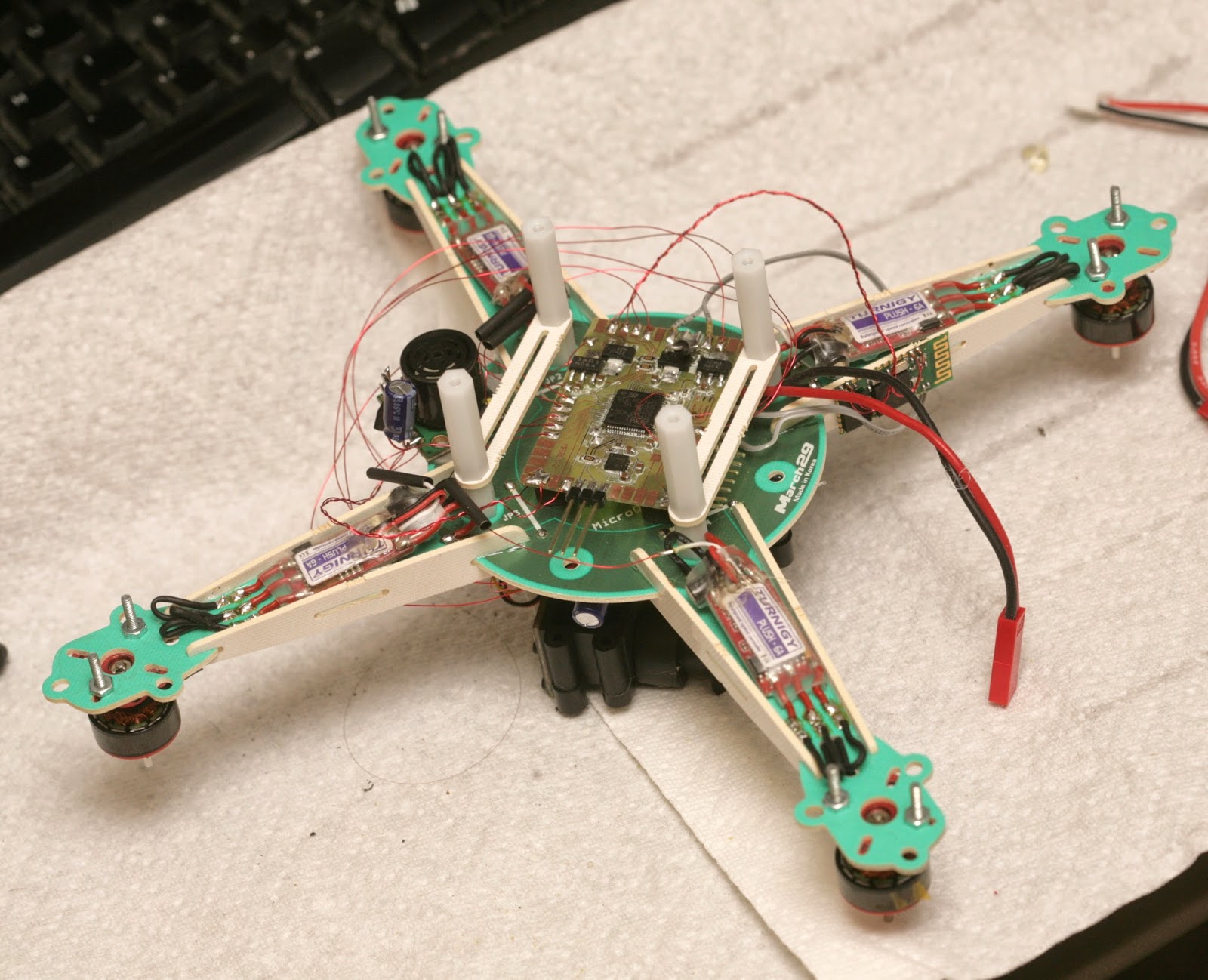
A 1st attempt at attaching everything led to a huge brick. It's going to be really slow. There's no durable way to attach the 2 LIDAR modules.
After a day of getting only error codes from the XV-11, the problem narrowed down to the rotation sensor. Then it became clear that it needed a very very specific signal from its rotation sensor.
Lacking any meanings for the error codes, the key was reading the rotation rate encoded in the packets. The internet claimed a very narrow range of 180-360 rpm being required. There was no way it could do more than 6 scans per second.
Even with a stock sensor that still spins, with the RPM perfectly dialed in, most of the readings were error codes. The stock motor needed to be down to 2.8V before it was slow enough. Then, there was routing the stock rotation sensor through the TX pin to capture it.
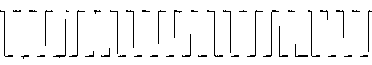
That revealed the exact direction of rotation & azimuth code, 14 pulses of 50% duty cycle & 1 pulse of 25% duty cycle. The 25% pulse needs to come after a 75% delay. It doesn't work if the pulse comes before the 75% delay. There definitely wasn't any margin in the software for any anomalies.

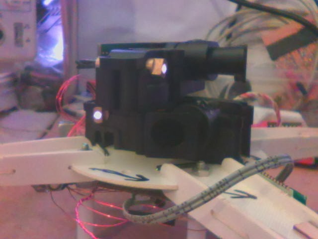
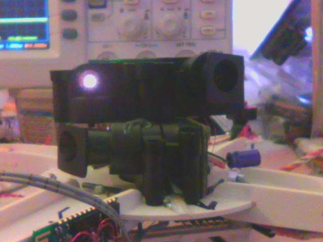

A crusty webcam reveals the IR laser. It would be bad to look at it. It's actually correlated to the rotation speed. It doesn't turn on if there's no rotation. It's very faint if the RPM is too high or too low. It's only fully on inside the narrow RPM range.
So hacking it to stay on with no rotation & using it as a horizontal range finder is a dangerous application of something that's safe in its normal application. You definitely need laser goggles.

RPM out of range

RPM in range
1 of the sensors failed. Tried focusing it, but it wouldn't detect farther than 1m.
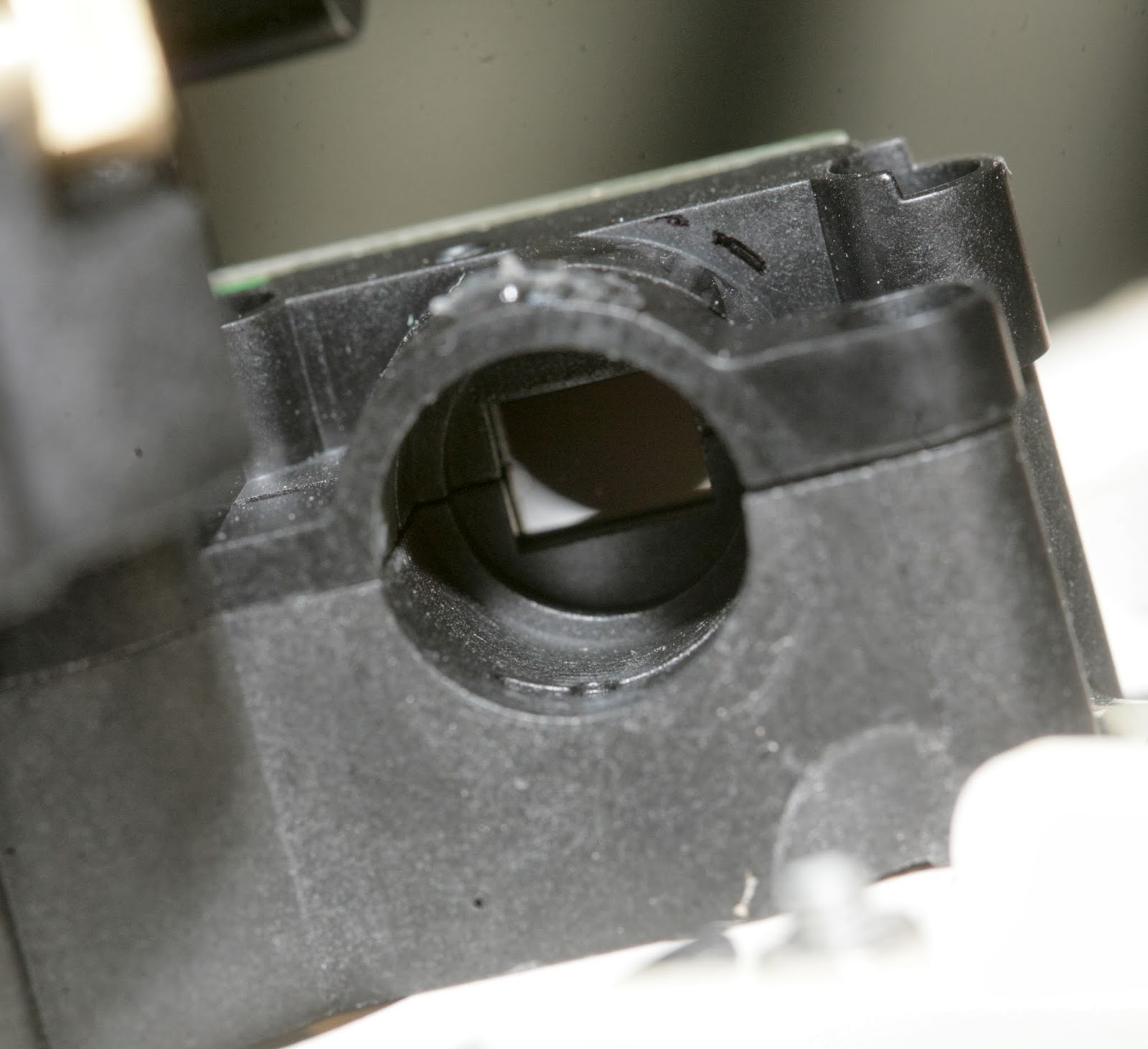
It doesn't have any focusing threads. It just slides in & out.
Tried bridging all the 3.3V regulators to cool off the board. It was melting off the standoffs from only 0.2A.
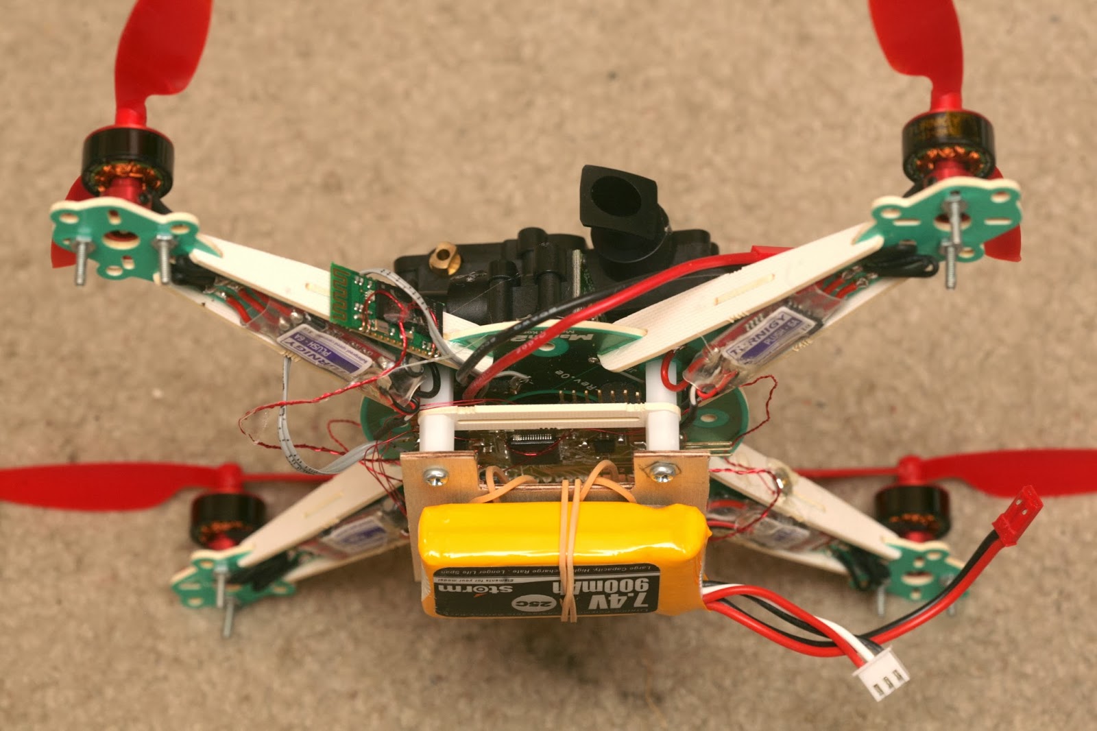
After a full day of replacing the sensor, the complete stack briefly flew manually. It took nearly full power. IMU drift was too high to fly more than a minute. 2 PWM pins were swapped.
The only way for the coordinates to work was to assume it was always pointing north. The calibration has to face the direction it's going to point when flying. Rotating the lidar output to point in any arbitrary direction caused massive glitches, every time it slightly rotated.
The video has several attempts to hover, several attempts at a waypoint mission. The waypoints failed because of an unknown software bug. The final flight was an attempt to hover, with the PID gains converging in on decent values. The testing ended when an arm broke, despite all the double layer wood.
Altimeter was all over the place. Seemed to be power distribution interfering with the cable routing or having the mane board under the frame.
Flight time was 2 minutes & maneuvering was real lousy. It definitely moved like a single female, very overweight & unwieldy.
It had to stay far from the walls to prevent crosstalk, yet be close enough to prevent detecting the floor. Didn't have any obvious floor detection at 1.5m from the walls & 0.3m altitude.
Velocity needed to be updated at 10Hz to have any success.
Absolute position was excellent. There was no more drifting.
Would recommend wearing laser goggles.
IMU drift made it drift. Would need to start over on the vibration problem, with the new board arrangement.
Comments
I had a version of this running for a little while. Beyond 3 feet all I saw was noise and I eventually gave up. I curious if the next ten model which was just released will be better?
You are really amazing Jack,
To do this on one of those tiny little quads, especially with a Laser scanner out of a vacuum cleaner is something I am sure no one else on the planet would even imagine attempting to undertake.
And to achieve the success you did - incredible.
Thank you for sharing this with us, my photo may have wiki ninja under it yours really should have mad scientist.
Best Regards,
Gary
Nice work Jack, thanks for sharing.
@gary - i'm interested in skywriting, is that something that is generally considered unfeasible at this point?
@Jack,
Nice presentation of the logical reverse engineering of this lidar for a new purpose!
Regards,
TCIII Admin
nu zan
That is very cool! I imagine this basic idea will be greatly miniaturized and added to our Multirotor inventory. Perhaps mounted on a high antenna.
Will there be quality skywriting though?
Brilliant - thanks for sharing and good luck in sorting your issues. Please keep us posted on your progress.