All Posts (14038)
Sort by
"...how to power those wings to beat 120 times per second? To keep this 60-milligram robot (the weight of a few grains of rice) with a 3-centimeter wingspan to a minimal size and weight, Wood says, you can’t simply use a shrunken version of the heavy DC (direct current) motors used in most robots. So he and his team settled on a simple actuator: in this case, a layered composite that bends when electricity is applied, thereby powering a micro-scale gearbox hooked up to the wings. Wood says the actuator works even better than its biological inspiration. The power density—a measure of power output as a function of mass—of a fly’s wing muscles is around 80 watts per kilogram; Wood’s wing design produces more than 400 watts per kilogram.
The first takeoff occurred late one evening last March, as Wood worked alone in his office, his colleagues gone for the evening. As the fly rose, Wood jumped up in celebration, quickly verified that his camera had captured the flight, and let out a sigh of relief."
Video:
- Part 1 About Curt and the basics of using an open source flight simulator for UAV simulation
- Part 2 (hardware notes, not really part of the interview)
- Part 3: GPS simulation
- Part 4: More advanced UAV simulation
- Part 5 (more hardware notes)
Basically, if you want to make a Propeller-based autopilot, Jason's done most of your work. No excuses now!
BTW, there are lots of other goodies in the Parallax object library, such as math libraries, floating point subroutines and PID routines.
- ArduPilot, a very low-cost navigation-only autopilot
- BlimpDuino, an Arduino-based autonomous blimp
- Quadrino, an Arduino-powered quadcopter (discussion thread here)
- ArduCopter, a helicopter autopilot project
- MikroQuad, an arduino-based quadcopter project
- Wash UAV, an Arduino-based autopilot for the Blade CX2 helicopter
- LEGO UAV, including autopilot code. Version 2, with a full 5 DoF IMU.
- Another NXT UAV, using a full IMU with gyros and accelerometers and GPS
- Overview of Basic Stamp UAV
- A step-by-step autopilot tutorial series can be found here
- Autopilot discussion
- AttoPilot, a powerful and inexpensive commercial autopilot
- OughtToPilot: A prize-winning Propeller-based fixed wing autopilot with full source code and documentation.
- OctoPilot: Propeller processor-based autopilot..
- Spyder, a Propeller-based quadcopter.
- Paul Hubner's PNav project: another Propeller-based autopilot
- Autopilot discussion
- IMU code
- Autopilot code
- UAV development board version 1 by Bill Premerlani
- UAV development board version 2 by Bill Premerlani
-
The ARM7 (using the Philips LCP214x chip) is the core of the open source Paparazzi project:- Paparazzi project home page
- Our Paparazzi "getting started" tutorial
- Our interview with one of the project leaders
- NG UAVP, a ARM7-based quadcopter project, based on the LPC2148 version of the chip.
- SparkFun tutorial on getting started with the LCP214x chip
ARM7 on SparkFun development board:
GumStix (Intel+Linux):
Ground-based controller:- Quadcopter with sensors onboard but autopilot running on a ground-based laptop
- Aerial imaging software for the N95 series
You can also see him interviewed in our PBS segment. It's fascinating to watch an ace engineer wrestle with some of the same issues that we find difficult, and because he's so focused on DIY and low-cost solutions, it's very appropriate for this site.
[UPDATE: We no longer recommend this GPS module, since it's incomptible with GPS simulators. The module we do recommend, the EM406, is described here.]
I had a little trouble when I first tried to get the Parallax GPS working, so this tutorial will help you avoid my mistakes.
First, DON'T place the GPS board right on your development board's breadboard. For some reason the GPS reception is terrible there, due to noise from other components. Instead, use another female-to-female servo connector cable (at least ten inches long; one of these is fine) and with it connect the three GPS pins other than /RAW to one of the dev board's servo ports that you're not using, as I've show in the picture.
Second, you're going to have to modify the demo code for the particular BASIC Stamp chip you're using. This took me forever to discover and it's definitely a shame that neither the manual or demo code mention this. You'll see in the code that there is this line:
T4800 CON 188
It tuns out that that 188 is just for the BS2, BS2e, and BS2pe chip. If you've got one of the other chips (I've got the BS2p) you need to change it. For the BS2sx and BS2p the number should be 500. For the BS2px it should be 813. (This info is buried in the BASIC Stamp Editor's help file in the SEROUT entry)
Also, change this line:
Sio PIN 15
To reflect whichever pin you've actually connected the GPS's SIO pin to.
Once you've made those modification the demo should run and you'll be able to copy the relevant code from that to your autopilot program.
If you're finding that this GPS just doesn't give you reliable enough performance, you may want to upgrade to a more advanced GPS module based on the 20-sat SIRFIII chipset. A good choice is this one from SparkFun, which is $10 cheaper than the Parallax module but offers much better reception. It's a bit trickier to interface with the Basic Stamp chip, so that's what we'll look at in the next tutorial.
Previous posts in this series:
Tutorial 1 -- Servos
Tutorial 2 -- Reading the Rx
As usual, I had the urge to design and build a new UAV airframe in one day. I woke up this morning and the gears in my head began turning about a new simple airframe design, so I started like I usually do with a sketch. I then moved on to cutting the basic shape out of a sheet of blu-core foam, making 2 pieces total then glueing them together with some gorilla glue. I also created a elevator and rudder using 1/4 in. foam board. Next I sanded the fuselage to make it more round and added the elevator, rudder, and balsa motor mount with outrunner motor. I also cut out the areas for the flight equipment. After all of that I added the neccessary radio equipment and wing mounting hardware to complete the building process.....just have to set the trim and wait for a good day to conduct a test flight.
When I conducted the test flight It turned out to be very slow and stable. I came to the conclusion that it was definately underpowered so I replaced the small 20-30oz outrunner to a electrifly rimfire outrunner 30-35-1250 which is capable of flying aircraft up to around 4 lbs which is right at my max allowable weight. I also upgraded to a 10x6E folding prop with a 55mm hub by APC and 50mm aeronaut spinner. I redesigned the motor mount to allow the motor to actually mount on the inside. I also made an air scoop just below the motor mount to help with cooling the motor/esc/battery.
Air Intake front view
Air Intake Batt. compartment view
Since the original post I have also put the PicoPilot into it own enclosure which makes mounting the reciever a little easier and also helps isolate and protect the autopilot.
I have also finally installed the Data Transceiver. I used a pair of Aerocomm CL4790-1000-232 transceivers, one removed from its enclosure for the UAV and one still enclosed for the base-station. I chose the Aerocomm data transceivers because of their ease of use and the already integrated RS-232 serial port, which made a plug and play interface for the GPS.
Data Transceiver and antenna
The GPS receiver was embedded in the top of the wing and covered with strapping tape, as is the majority of the bottom side of the wing and the fuselage for added strength and durability. The final weight minus imaging/video equipment came in at 2lbs 6.75oz
SPECS.
Name: MRASV-3 (Medium Range Aerial Surveillance Vehicle / Ver. 3)
Wingspan: 48''
Length: 33"
Weight RTF: Under 4lbs
Autopilot: UNAV Picopilot NA (32 WP Navigation / ALT hold)
Duration: 30min @ 30mph cruise speed (just below 1/2 throttle)
The code here will test your hardware and see if it's working. The aileron stick on your RC transmitter should drive the servo (it's a little jerky, due to processor delays, but nothing too serious). When you flip the gear switch (channel 5) on your transmitter, the board will go into "autonomous mode" and move the servos itself. Flip the switch back and you're back in manual control.
Next, we'll connect the GPS in this post.
Previous posts in this series:
--Getting started with servos
First, let's just set up the board to control a single servo with the FT639 chip on the Parallax development board (later on I'll show you how to do it using the Parallax servo controller board, if you prefer that). The single FT639 chip has the advantage of being small and easy to integrate into a single-board autopilot, but it's not the greatest servo controller in the world and doesn't handle high-speed applications well (we're just using it on the rudder, so it's fine for our purposes).
In this case I've connected the FT639's serial-in pin to the Stamp's pin 8 (yellow wire), and the FT639's servo 1 output pin to the signal pin to servo connector p15 (blue wire). The black and red are ground and power, of course. Couldn't be easier.
Here's the code that just tests this servo in several position. Once you get this working, the next step will be to read the R/C receiver input signals and pass them through to this servo. Go to this next post here.
Curtis Olson, best known as the creator of the open-source FlightGear flight simulator, has done the best work of building on the Crossbow code. He's recently released the source code to his Microgear autopilot, which uses the Crossbow IMU hardware and replaces the Crossbow processor unit, known as Stargate, with a much more powerful Gumstix Linux single-board computer. He's also released the groundstation software (shown), which naturally works with FlightGear. He describes the project well here.
This is a little out of our league at DIY Drones, both in price and complexity, but for those you who want to go deeper on autopilot theory, a browse through Curtis's source code is very instructive. He's written it in C++ and done a pretty good job with comments, so it's not too hard to parse. The Kalman filter is still a little over my head, but I thought the waypoint handling was very clear.
If you're interested in learning more about the Crossbow (often known as Xbow) hardware and software, Tony Truong Giang Le has some good tutorials here and here.
New rules from the DOT concerning airtravel and LiPo batteries. Thank goodness we have reliable Plastic Bags to protect us!!
;-)
Paul
First I must thank Jeffrey Johnson who posted a set of images of the Cularis he is building for photo mapping. He has made a really neatmodification by moving the rudder and elevator servos from the stockposition in the cockpit, to tail mounting in the fuselage. Not onlydoes this free up space in the cockpit area, which will make it easierto enlarge to take the camera, but it also moves some 35gm of weightto the rear. This should greatly help in balancing the plane withoutadding too much lead.
I have also now read some 670 posts in the Cularis building thread on the rcgroups forum. There is a wealth of good stuff there, includinga number of modifications to the stock kit to improve performance and ease of use. Specifically, I now plan to do the following.
- Extend the travel of the flaps by reversing the control horns, thus allowing for slower landings
- Reverse the direction of one of the flap servos so that if can be connected to the other flap servo with a simple Y lead.
- Remove some 30% of the hinge material from the ailerons and flaps to reduce the load on the wing servos.
- Cut away the stock mountings for the mating connectors in the wing roots and run the cables through to connect by hand. This seems to be amajor cause of poor reliability as if the wing moves a little inflight, the connectors can cease to make contact, leading to loss ofcontrol in the wing.
- Replace the side canopy latches with a single magnetic mount on the rear bulkhead. This also makes it easier to enlarge the cockpit area totake the camera.
- Move the servos for rudder and elevator to the rear.
- Sand the trailing edges of the rear stabilizers a little to reduce drag.
There is one other modification that I am in two minds about and that is a secondary means of fixing the wings. In the stock kit, the wings areheld in place with plastic catches. These are design to open in theevent of a heavy landing so that the wings break away. If wouldseem, however, that some have opened in flight leading to spectacularcrashes. Jeffrey has a a similar modification to several shown inthe thread that involve using a secondary pin through the wing root.While this will certainly keep the wings solidly in place, I am notsure if it is better or worse in the case of a bad landing.
Building a UAV for phot mapping - Previous Posts
Ahh!! CRASH and BURN!!
I had planned to use the Pico-Pilot and Pico-GPS for the autopilot in my UAV, but I have now discovered that since Jan 2007, they have been classed as MILITARY technology and are controlled by US Export License regulations. Specifically theregulations cover,
a. “UAVs” having any of the following:
a.1. An autonomous flight control and navigation capability (e.g., an autopilot with an Inertial
Navigation System); or
a.2. Capability of controlled flight out of the direct visual range involving a human operator
(e.g., televisual remote control).
b. Associated systems, equipment and components as follows:
b.1. Equipment specially designed for remotely controlling the “UAVs” controlled by 9A012.a.;
b.2. Guidance or control systems, other than those controlled in Category 7, specially designed for
integration into “UAVs” controlled by 9A012.a.;
b.3. Equipment and components specially designed to convert a manned “aircraft” to a “UAV”
controlled by 9A012.a.
Note: 9A012 does not control model aircraft.
Despite the last sentence, UNAV, who make the Pico Pilot have now told me that none of the applications for export licenses they have made thisyear have yet been granted. Back to the drawing board.
The other common low cost option for an autopilot seems to be based on the FMA Co-Pilot for flight stability with an additional board suchas the RCAP2 plus a GPS receiver for navigation. While a cheaperalternative, I had already discounted this approach because it isbased on thermopile sensors. For my terrain, I cannot get a clear360degree view of the horizon to calibrate the system before launch.In addition, the various different terrain types , forest, grassland,lakes etc. could give problems in flight, irrespective of thetemperature differences that can occur if different parts of a valleyare in sunlight or shade.
During my initial research into autopilots, I also looked at the Paparazzi project. While there is a wealth of open source stuff there, thecurrent Tiny autopilot still uses thermopile sensors for stability,although it does have an on board GPS unit for navigation. An all singing, dancing IMU with gyro's , mangetometers etc. is under development. Althoughall the designs are published, there is still no commercial source ofassembled units or PCB's.
A recent post on this forum (can't find it now), talked about the the UAV development board from Sparkfun. I had a brief look at this, butinitially discounted as they claim that the firmware is a guidelineonly. It is also written in assembly code and I am far to old tostart writing in assembler again. Still I shall have another look atthis over Christmas, as the board does have a proper IMU with 2 gyrosand a 3 axis accelerometer.
Conclusions and Questions
- I cannot use my prefered autopilot option owing to US export regulations.
- What other, non US manufactured, commercial autopilots are people using?
- Any other suggestions for a home built unit with an IMU rather than thermopiles?
Building a UAV for phot mapping - Previous Posts
In addition, they have only a small fraction of a pro UAV's feature set. I was reminded of this as I was looking at the source code for the Micronav software for the Crossbow hardware (shown), which one of the more sophisticated open source autopilot programs (but is still at the bottom end of the pro autopilot range).
Here are some of the things the Micronav software code has that we don't:
--Full avionics and telemetry data downlinked to the ground.
--A proper custom inertial measurement unit (IMU), using gyros and accelerometers and Kalman filters in software
--Data logging
--Smart ("look ahead") waypoint finding algorithms, that don't just get to a point but get to it efficiently and along a predictable line.
--Corrections for what part of the Earth you're flying over (northern or southern hemisphere).
--Use standard UAV commands for dynamic mission/waypoint changes, such as "loitering" over a target.
--Ground station software
Other autopilots have such features as:
--Automatic adaptation to different airframe platforms after inputting a pre-recorded flight from that aircraft.
--Auto-land and take-off
--Communications between camera and autopilot so you can steer the camera and let the plane steer itself
--Etc...
We'll get some of those feautures someday in our own UAVs, but for now we take all sorts of shortcuts to stay within the reach of amateurs. For instance, we usually don't build our own IMUs. The DIY Drones approach is to let some off-the-shelf hardware handle the tricky job of stabilization and our custom hardware and software just handles the easier 2D job of GPS navigation. We don't have any ground station software for real-time control and communications (just software for post-processing of imagery). You've got to hand-tweak the autopilots for each new airframe. And we let commercial GPS receivers handle the job of data logging.
Anyway, if you want to be reminded of how much math you've forgotten since college, check out the source code. And then be thankful for all we've spared you!
The first image shows the recommended distribution of components for the electric version of the Cularis. (Click for higher resolution). In this configuration, the plane balances at the CGO with 3 weights (supplied in the kit) fixed under the tail plane. The component weight budget is
- Motor/Prop Assemply 225gm
- Multiplex ESC 34gm
- Fight Battery 149gm
- 7Ch Rx 30gm
- Rx Battery 112gm
- Cularis cable set 50gm
- 6 servos 70gm
This gives a total of 670gm. The manufactures claim an all up weight of 1680gm with a wing loading of 30.5g/dm2.
In this image, I have added the Pentax A30 camera and a PicoPilot with PicoGPS. The camera is about 8mm wider than the center opening in the fuselage, so I will have cut back the sides for it to fit. I will also machine out a stepped hole in the base for the extended lens to sit in and see through. If I try to locate the camera further back, then I will have to machine out the two servo openings as well.
The addional weight is
- Pentax A30 with battery and SD Card 150gm
- Pico Pilot and GPS 63gm
However, I think the real problem is not the weight but the COG. A simplified calculation of the moments of the camera, the autopilot and the new position of the Tx about the COG, suggest that I will have to add about 70gm to the tail in order to bring the plane back into balance. So the total additional weight will be in the order of 283gm. This will increase the all up weight to 1963gm with a 16% increase in wing loading to 35.6g/dm2.
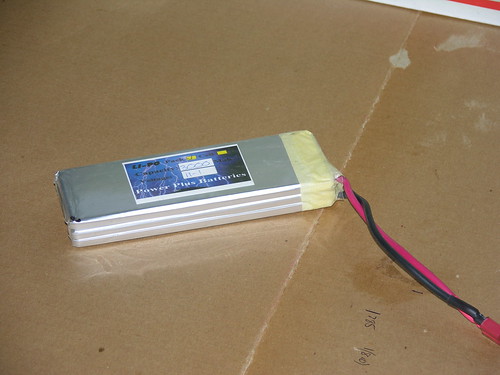
Although it may be standard practice, I am not really happy about have separate Fight and RX batteries. There are two things to charge and check before each flight and it just seems more elegant to have a single power source with a switch mode SportsBEC. With some searching, I found a DuraMax UltraPro 3s 3600mA Li-po with a flat form factor. The dimensions are 145mm x 50mm x 16.2mm. With a small amount of machining, this will fit in the space previously occupied by the Rx battery. The weight at 280gmplus a Sports BEC is only 35gm more than the previous batteryconfiguration. The real gain is in the balance, as the new heavierbattery is behind the COG.
By moving the Rx and autopilot back as shown, the balance weight reduces to 25gm, so in all this solution is a little lighter than the previous one and I get more battery power
Conclusions and Questions
- With some careful cutting, I can fit the camera and PicoPilot into the Cularis airframe.
- What will happen to the performance of the plane with a 16% increase in wing loading?
- Is it a good idea to use a single battery with a SportsBEC? How about noise on the 5V power for the autopilot and GPS?
Building a UAV for phot mapping - Previous Posts
our bird the A-3
yamaha R-MAX flown by georgia tech
taken with 7mgp camera and own design foamy
marymoor rc park
sweet uav !!