In this project, I will go through the process of designing and making a flight controller board from scratch for a micro-quadcopter. This board will be based on the ATMega328 microcontroller and will be used to control four coreless DC motors. The whole PCB making process from designing of the schematic to gerber viewing is done using EasyEDA. The main idea while designing the flight controller board was to keep it small, lightweight while still making it easy enough to solder at home. Therefore I chose to use as many SMD components as was feasible to solder. The ATMega328 chip and MOSFETs are the SMD components used on this board. Though in hindsight I have also used 1206 SMD resistors and capacitors as they are easy to solder even for hobbyists.
1. Designing the schematic and PCB
If you are interested in the circuit project, you could access circuit and PCB project for the micro-quadcopter . The schematic designing process was very smooth and intuitive on the EasyEDA environment. Anyone with previous experience in other circuit design tools would easily adapt to it. I found it much more preferable than dealing with messy etchant used for making home-brew PCBs. The circuit schematic is as image showed and could be edited Here: https://easyeda.com/editor#id=d26e0216b68649e0b102da0a51664bef
Using the Convert To PCB option the blank PCB and component footprints were generated. All the component footprints used were available in the EasyEDA Component Library. In case you cannot find the component, EasyEDA also has a handy custom component creating tool. The PCB outline, dimensions, hole dimensions, silk screen color can all be customized using the useful right-hand side menu on the screen. Screenshots of the PCB design screen below and can be edited Here: https://easyeda.com/editor#id=b6e2e30d14264213aea6a2ebbdde2108

2. Custom PCB and prepare compents for the Quadcopter
Once the PCB was designed and finalized, you can finalize the number of copper layers you need, the PCB thickness, copper weight, and even the PCB color from the checkout menu. There is also a handy option of downloading your Gerber File on the PCB order page and seeing the Photo View of your PCB (i.e. how it will turn out). And you also could custom circuit board with JLCPCB.
Then prepare main components used in this board are:
- ATMega328 TQFP32 Package with 16MHz Crystal x 1
- Si2302 MOSFETs x 4
- 78L33 LDO Voltage Regulator x 1
- NRF24L01 Transceiver Module x 1
- MPU6050 Acc/Gyro Module x 1
- Coreless Motors x 4
3. Soldering and Final Build
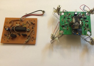
After all components on boards is soldered and the quadcopter is well built, I can quickly go on to the coding and testing of the project. I have included some pictures of the final quadcopter build that I made using these boards. Also, I have included a picture comparing a home-made board to a professionally made PCB and you can see the improvement in quality. Hope you will enjoy this project.