All Posts (11072)

Sort by

Step by Step Assembly Guide: Freewing F 35C 110 mm EDF Jet (PNP Gyro Version, Item FJ50111PG)

Freewing F-35C 110mm EDF jet manual(2026 new)

Freewing F-22 Raptor v2 90mm edf jet manual(2026 new)

This build follows the official factory workflow, optimized for the 1/9.6 scale 110 mm F 35C with QUICK II tool free quick release wings, pre installed servos, 6 axis EG01 gyro, sequenced electric retract landing gear, LED navigation/afterburner lights, and a factory mounted 110 mm in runner EDF + 130 A HV ESC (12S power).
Air Force
Pre note: Most electronics (EDF, ESC, gyro, landing gear servos, LED wiring, fuselage servos) are pre installed in factory. Only airframe assembly, wiring plug ins, radio binding, battery fitting, control linkage tuning and CG setup are required.
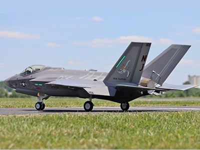
Freewing F-35C Lightning II Super Scale 110mm EDF Jet


Freewing F-35C Lightning II Super Scale 110mm EDF Jet

Discover more
Drones & RC Aircraft
RC Electronics
Shipping Services



Freewing K-8 Karakorum 80mm EDF PNP Jet


Freewing K-8 Karakorum 80mm EDF PNP Jet


Tools you need

Phillips head screwdriver (1.5 mm 3 mm)
 
Tape (to protect EPO foam from scratches)
 
Zip ties (for cable management)
 
Double sided hook and loop tape (battery mounting)
 
Digital scale + balancing stand (for CG check)
 
12S Li Po battery (6 000�C8 000 mAh, 60C�C100C discharge rating)
Electricity
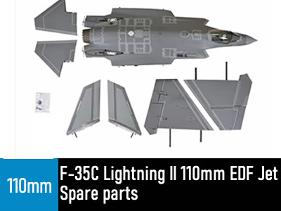
Freewing F-35C Lightning II 110mm EDF Jet Spare parts

Freewing F-35C Lightning II 110mm EDF Jet Spare parts


All Spare Parts are available in stock.

1. Send email to us,our e-mail is sales@freewing-model.com

we will reply message within 24 hours.

2.Live Chat Online in the following,


Discover more
Physics
Defense Industry
Boats & Watercraft


This Product is available in stock,we will ship the package box within 48 hours after the buyers pay money via paypal.


Spare parts For Freewing F-35C Lightning II 110mm EDF Jet Spare parts
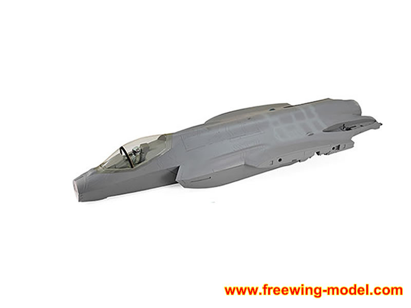
Parts NumberDescriptionImage
FJ5011101Freewing F-35C Lightning II 110mm EDF Jet FuselageFreewing F-35C Lightning II 110mm EDF Jet Fuselage
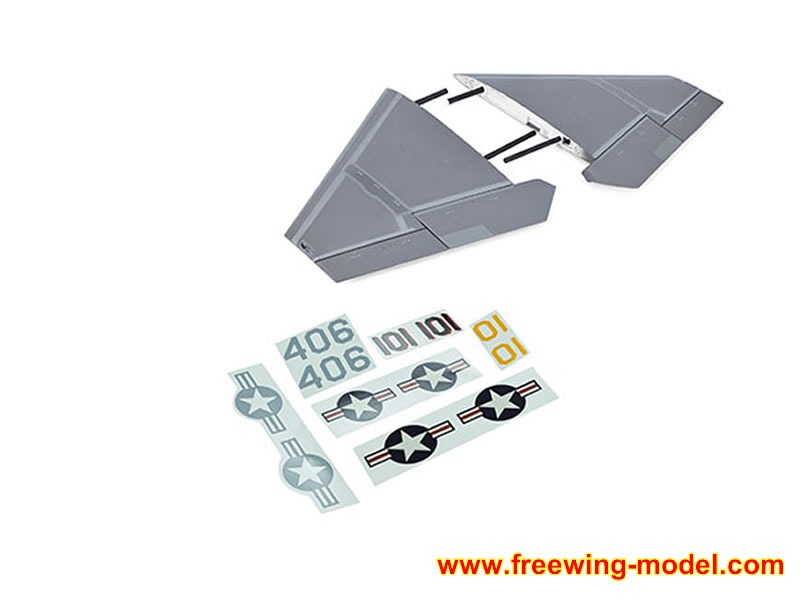
FJ5011102Freewing F-35C Lightning II 110mm EDF Jet Main wingFreewing F-35C Lightning II 110mm EDF Jet Main wing
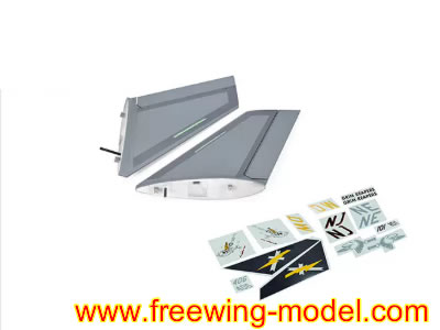
FJ5011103Freewing F-35C Lightning II 110mm EDF Jet Vertical StabilizerFreewing F-35C Lightning II 110mm EDF Jet Vertical Stabilizer
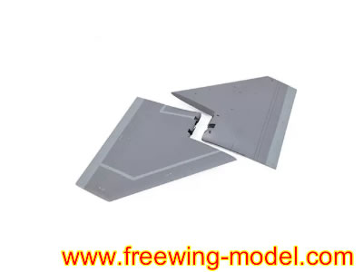
FJ5011104Freewing F-35C Lightning II 110mm EDF Jet Horizontal Stabilizer SetFreewing F-35C Lightning II 110mm EDF Jet Horizontal Stabilizer Set
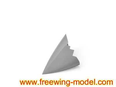
FJ5011105Freewing F-35C Lightning II 110mm EDF Jet Nose ConeFreewing F-35C Lightning II 110mm EDF Jet  Nose Cone
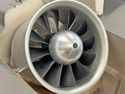
110mm EDFFreewing 4678-680KV Inrunner Motor 110mm 12-blade EDF 6S Power SystemFreewing F-35C Lightning II 110mm EDF Engine Power system
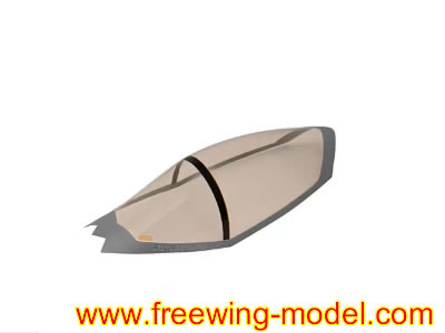
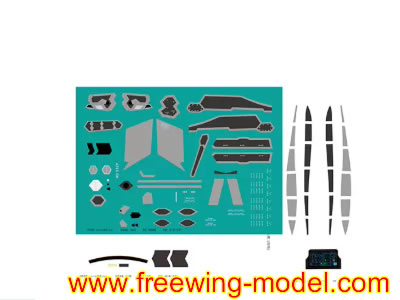
FJ50111061Freewing F-35C Lightning II 110mm EDF Jet CockpitFreewing F-35C Lightning II 110mm EDF Jet Cockpit
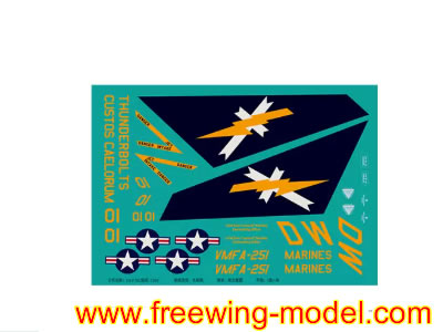
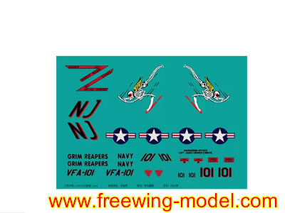
FJ50111071Freewing F-35C Lightning II 110mm EDF Jet Decal AFreewing F-35C Lightning II 110mm EDF Jet Decal A
FJ50111072Freewing F-35C Lightning II 110mm EDF Jet Decal BFreewing F-35C Lightning II 110mm EDF Jet Decal B
FJ50111073Freewing F-35C Lightning II 110mm EDF Jet Decal CFreewing F-35C Lightning II 110mm EDF Jet Decal C
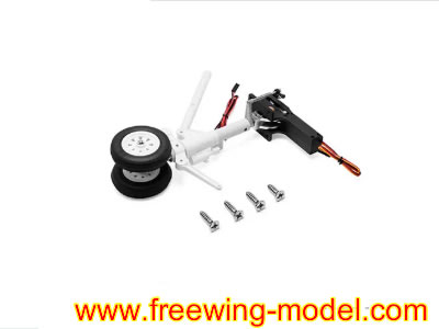
FJ50111081Freewing F-35C Lightning II 110mm EDF Jet front Landing set Strut and Wheel with RetractFreewing F-35C Lightning II 110mm EDF Jet front Landing set Strut and Wheel
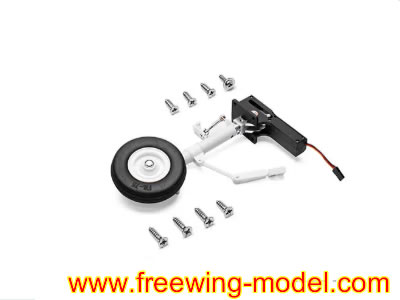
FJ50111087Freewing F-35C Lightning II 110mm EDF Jet Left Landing set Strut and Wheel with RetractFreewing F-35C Lightning II 110mm EDF Jet Left Landing set Strut and Wheel with Retract
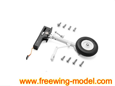
FJ501110812Freewing F-35C Lightning II 110mm EDF Jet Right Landing set Strut and Wheel with RetractFreewing F-35C Lightning II 110mm EDF Jet Right Landing set Strut and Wheel with Retract

All Spare Parts are available in stock.

Radio Control & Modeling
Discover more
Model Rockets
Radio Control Drones
Propeller Airplanes
 

1. Send email to us,our e-mail is sales@freewing-model.com

we will reply message within 24 hours.

2.Live Chat Online in the following,

Stage 1: Horizontal stabilizer (Elevator) installation (tail first)

  1. Align the plastic adapter lugs on each left/right horizontal stabilizer into the pivot slots on the rear fuselage tail boom.
  2. Plug the elevator servo extension wire from each horizontal tail into the matching fuselage servo plug.
  3. Center the elevator surface perfectly, then secure the two side horizontal tail mounts with FA3��8 mm machine screws (4 total). Do not over tighten; over torque will strip EPO foam threads.
  4. Check free elevator travel: full up/down motion without binding or cable snagging. Secure loose wiring with zip ties inside the fuselage tail cavity.

Stage 2: Twin canted vertical stabilizers (Rudders) assembly

  1. Route vertical tail servo wires through the fuselage vertical fin mounting holes. Connect each rudder servo plug to the fuselage extension harness one by one.
  2. Seat each canted vertical fin fully down onto the fuselage rear mounting bosses.
  3. Fasten using 4�� FA3��8 mm screws to lock the vertical stabilizers in position.
  4. Manually test rudder left right movement; confirm wiring is not pinched between stabilizer and fuselage frame.

Stage 3: Main wing installation (QUICK II tool free plug and lock system, signature for this 110 mm F 35C)

This model uses a carbon fiber main spar plus push button quick lock latches (no wing mount screws required for field assembly):
Aviation Industry
  1. Slide the thick main carbon fiber spar fully through the fuselage wing root tunnel, spanning left to right wing sockets.
  2. Unlock the wing latch buttons on both fuselage sides (press the button down to release the lock mechanism).
  3. Plug the aileron flap servo plugs from each main wing into the corresponding fuselage harness connectors. Double check polarity (pin alignment) to avoid reversed servo operation.
  4. Slide left right main wing wing root lugs onto the carbon spar, push the wings flush against the fuselage shoulder.
  5. Release the latch buttons. The spring loaded latches will pop up and mechanically lock the wings firmly onto the airframe. Gently tug each wing to confirm zero play.
For long term static display: Optional set screws can be tightened for extra wing rigidity; leave loose for easy transport disassembly.

Stage 4: Nose section, cockpit canopy and intake duct fit up

  1. Fit the plastic cockpit tub/pilot detail piece into the forward fuselage cockpit cavity.
  2. Clip the clear canopy hatch onto the fuselage nose cockpit hinge points; confirm the canopy latches shut securely.
  3. Install the nose cone; ensure the intake air duct channel inside the nose perfectly aligns with the front inlet leading to the 110 mm EDF unit. Any gaps will reduce EDF thrust performance. Seal minor intake gaps with thin foam tape if there is air leakage.

Stage 5: Landing gear & sequenced gear door pre check (factory pre mounted electric retracts)

All landing gear servos, shock absorber struts, gear door servos and sequencing wiring are pre installed:
  1. Connect the landing gear harness plug to the main gyro/central electronics board inside the fuselage.
  2. Power the system on (via temporary battery) and cycle landing gear up/down on your radio transmitter.
  3. Verify the gear doors open first, struts extend, then doors close (scale sequenced operation). Adjust servo linkage set screws if doors bind, stay ajar or jam.
  4. Check nose gear steering movement matches your transmitter rudder input.

Stage 6: LED & afterburner light wiring connection

  1. Locate the navigation light plug (wing/fuselage formation lights) and afterburner LED plug (exhaust nozzle) inside the rear fuselage.
  2. Plug both into the dedicated LED port on the Freewing EG01 6 axis gyro unit.
  3. Test: Navigation lights turn on when the radio system powers up; the afterburner LED illuminates under high throttle input (factory pre programmed).

Stage 7: Radio system wiring, gyro setup and transmitter binding

  1. Plug these components into the EG01 gyro input ports:
    • ESC signal wire
    • Aileron, elevator, rudder servo main harness lead
    • Landing gear servo harness
    • LED lighting harness
  2. Bind your 2.4 GHz receiver to your radio transmitter, then plug the receiver into the gyro��s receiver input port.
  3. Gyro baseline setup (critical for this large jet):
    1. Place the jet on a perfectly flat, level surface, keep the aircraft stationary.
    2. Power on the radio first, then plug in the 12S flight battery to power the jet.
    3. Hold the trim sliders neutral while the gyro auto calibrates (LED flashes solid once calibration finishes).
    4. Set gyro gain on your transmitter (start at 50 60% for maiden flight; increase for smoother high speed flight, reduce if the jet oscillates/wobbles).

Freewing F-35C Lightning II Super Scale 110mm EDF Jet


Freewing F-35C Lightning II Super Scale 110mm EDF PNP Jet
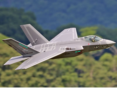


Freewing F-35C Lightning II 12S 110mm ARF Plus jet


Freewing F-35C Lightning II 12S 110mm ARF Plus jet


Stage 8: Battery installation & Center of Gravity (CG) tuning (most critical flight step)

  1. Open the top fuselage battery hatch behind the cockpit. Secure the 12S Li Po battery using hook and loop tape on the battery tray.
  2. Official CG datum for the Freewing 110 mm F 35C: 110�C115 mm back from the leading edge of the main wing root (fuselage wing shoulder).
    • Move the battery forward if the nose pitches up (tail heavy, unstable).
    • Shift the battery rearward if the nose dives sharply (nose heavy, sluggish turns).
  3. Once CG is correct, secure excess battery power wiring with zip ties to prevent loose wires from hitting the 110 mm EDF fan.

Stage 9: Final pre flight control surface check

  1. Double check all control surface directions:
    • Aileron: Right stick right next right aileron dips down
    • Elevator: Right stick back next elevator deflects upward
    • Rudder: Left stick left next vertical tail rudder moves left
  2. Reverse servo direction in your radio menu if any surface moves backwards.
  3. Cycle landing gear, test flaps, check all wiring is clear of moving parts and the EDF inlet/exhaust.
  4. Inspect the 110 mm EDF fan; ensure zero debris inside the fan shroud before the maiden flight.

Quick assembly order recap (field setup version for flying field fast build up)

  1. Attach horizontal tails . 2. Attach vertical stabilizers . 3. Install carbon spar + lock on main wings next 4. Plug in all servo/LED plugs next 5. Mount battery next 6. CG balance next 7. Gyro recalibrate next 8. Pre flight check next Fly

Freewing K-8 Karakorum 80mm EDF PNP Jet
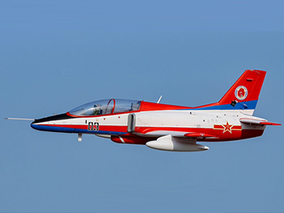
Freewing K-8 Karakorum 80mm EDF PNP Jet


Freewing K-8 Karakorum 70mm EDF PNP Jet

Freewing K-8 Karakorum 70mm EDF PNP Jet


3.Freewing F-35 110mm EDF jet

Air Force
Freewing F-35C Lightning II Super Scale 110mm EDF Jet with Gyro RC Airplane

Read more…

EFT N680: Entry Level DIY Drone Platform

Published: 9, 24, 2026 , | Written by Louis, Technical Department Manager

Programmable drones on the market generally fall into two categories. The first includes block based programming toys that are affordable and well suited for short term, hands on experiences. However, these systems are essentially closed “black boxes.” Once students want to explore the underlying logic behind flight control decisions, they offer limited opportunities for deeper technical learning. 


The second category consists of high performance, open source research platforms. While these platforms provide extensive development capabilities, they are often expensive, delivered as bare bone kits, and require a relatively high level of technical knowledge. This creates a steep learning curve for students who are just beginning to explore drone development. coding drone

The EFT N680 is designed to bridge this gap.

As an entry level open source drone development platform, the N680 enables new students to progress from basic hands on training to real flight testing, while giving graduate students and advanced learners a practical platform for algorithm research and academic projects. Its flight control architecture is open at the core, while its modular design allows students to inspect, maintain, and replace individual components themselves.

With comprehensive technical documentation and supporting software, instructors can integrate the N680 into existing courses without having to redesign the entire curriculum.

 31268874897?profile=RESIZE_710x

What Is the EFT N680?

The EFT N680 is a 680 mm wheelbase quadcopter open source drone development platform. Unlike closed educational drones that rely primarily on simplified demonstration applications, the N680 is a professional experimental platform designed to combine stable flight performance with hands on, in depth learning.

Its unified airframe and open source flight control system make it particularly suitable for universities, vocational schools, STEM program leaders, and drone developers. education drone The platform is open and easy to maintain, allowing for repeated use in teaching across academic years. 


Design and Configuration

The N680 adopts a fully modular architecture. Its main frame uses a high strength, one piece injection molded nylon structure, combined with carbon fiber arms and landing gear. The fuselage provides ample internal space and reserved mounting points for payloads and peripherals, allowing students to integrate cameras and other equipment for experiments such as aerial imaging and visual navigation.

Featuring a modular design, components such as the arms, motors, ESC/PDB, propellers, snap-fit sealed battery compartment, and flight controller can be replaced independently, facilitating assembly, setup, and maintenance. entry level drone

This modular approach is particularly valuable in classroom environments. If a component is damaged during a test flight, students can replace the affected module instead of replacing the entire aircraft. This helps minimize downtime and keeps practical training on schedule. 

A single N680 can support multiple educational experiments covering flight principles, propulsion systems, embedded control, and complete aircraft assembly.

Open Source Flight Control and Development

The aircraft is equipped with the N1 mini open source flight controller, built around a high performance STM32H7 processor.

It features a built in high precision magnetic compass and can be paired with an external GPS compass to provide redundant heading sensing and improve positioning stability.

The flight controller provides a broad range of peripheral interfaces, including 8 motor output channels and 4 servo channels, with reserved expansion buses for CAN, serial, and I2C devices.

The N680 natively supports ArduPilot open source firmware and the MAVLink communication protocol, allowing students and developers to work within a mature open source ecosystem supported by extensive documentation and community resources.

A Progressive Learning Path

The N680 is designed around a progressive learning path.

At the beginner level, students can use ArduPilot to configure and test flight modes, parameters, and waypoint missions. This allows them to understand fundamental drone control concepts through direct interaction with a real aircraft rather than relying solely on simulation or block based programming.

At the advanced level, users can connect an onboard computer and deploy ROS nodes, with access to attitude, position, and velocity control commands. This creates opportunities for projects involving machine vision, autonomous navigation, and other advanced drone applications.

The onboard computer is an optional accessory, while the flight controller includes reserved expansion interfaces for integration.

EFT N1 Assistant Software

The N680 is supported by EFT N1 Assistant, a lightweight parameter tuning application designed to make configuration and debugging more approachable for beginners.

The software provides real time access to attitude data, EKF status, GPS signals, and RC channel data. It also supports flight parameter configuration and log playback, giving students and instructors the ability to review flight data after class.

This makes the same software suitable for both introductory training and more advanced secondary development.

RC Lite Remote Controller

The N680 comes standard with the RC Lite remote controller, featuring an industrial, minimalist design and high precision Hall effect joysticks for smooth and responsive control.

It uses two removable 18650 batteries, supporting direct charging and quick battery replacement.

With 16 output channels, the controller provides the basic channels required for flight control while leaving additional channels available for customized control of expansion payloads such as cameras and deployment devices. This makes the system suitable for a wide range of student innovation and engineering projects.


Flight Performance and Power Characteristics

The N680's flight performance specifications are calibrated by EFT's inhouse R&D team rather than being theoretical figures intended only for product display.

Its power reserves allow the platform to maintain stable and controllable flight while carrying payloads. The airframe can directly accommodate gimbals, thermal imaging modules, and customized sensor kits without requiring structural modifications.

The platform is equipped with a 6S 8000 mAh lithium ion battery, providing approximately 18-27 minutes of flight time under standard operating conditions. Exact performance depends on payload weight and flight mode settings.

The battery supports quick installation and removal. When paired with the included 300 W high power charger, it takes approximately 45 minutes to recharge from empty to full, helping reduce charging downtime during classroom experiments effectively.


Application Scenarios

Drone Beginners

The kit includes the essential hardware required to build the aircraft. Its modular architecture helps reduce the learning curve and allows students to develop a practical understanding of the complete drone system through hands on assembly and training. 

DIY Development Enthusiasts

The N680 combines high quality hardware with a proven industrial grade structure, providing a stable and reliable flight platform while giving users the opportunity to learn through assembly, configuration, testing, and debugging.

College Students and Research Developers

Native compatibility with the ArduPilot, MAVLink, and ROS ecosystems makes the N680 suitable for university courses, laboratory experiments, and research projects involving flight control algorithms, machine vision, autonomous navigation, and related technologies.

Industry Innovators

With extensive expansion interfaces and available payload capacity, the N680 can also serve as a practical platform for rapidly validating prototypes for applications such as aerial imaging, surveying, and inspection.

 colleague education drone

31268875272?profile=RESIZE_710x

What's Included in the Kit

The N680 is available in three configurations to meet different laboratory and training requirements:

  1. PNP Kit Includes the N680 frame, 4 E4 motors, 4 30A ESCs, and 4 15 inch folding propellers. This configuration is suitable for laboratories that already have compatible flight controllers and remote control equipment.
  2. RTF Kit Includes all components of the PNP kit, plus an N1 mini flight controller, GPS module, RC Lite remote controller, EB608 6S 8000 mAh battery, and 300W charger.
  3. RTF Flight Case Kit Includes everything in the RTF kit, plus an aviation transport case for moving equipment between classrooms and outdoor flight test locations.

All components are also available separately as replacement parts. Importantly, all kits are delivered as unassembled components. Users are required to complete the aircraft assembly and parameter tuning themselves. The EFT N1 Assistant tuning software provides guided tutorials, while the assembly and tuning process itself forms an important part of the handson training experience.  beginner friendly drone


Specifications

N680 Drone Platform

Item

Specification

Wheelbase

680 mm

Frame Weight

2.5 kg

Maximum Takeoff Weight

4.7 kg

Unfolded Dimensions

867 × 860 × 316 mm

Propeller Size

15 inch

Rotor Count

4

Motor Model

4214

Supply Voltage

6S

KV Rating

380 rpm/V

ESC Model

4-6S/30A

N1mini Flight Controller

Processor

STM32H743

Accelerometer & Gyroscope

ICM-42670-P

Electronic Compass

QMC5883P

Barometer

SPA06-003

Operating Voltage

5V

Dimensions

45 x57.1 mm

RC Lite Remote Controller

Dimensions

275.05 x 178.1x 98.65 mm

Battery

2 x 18650 Batteries

Operating Frequency Band

2.4GHz

Control Range

1km

Charging Port

USB-C

Weight

1.5kg

Battery Runtime

5-7h

RF Output Power

20 dBm

Operating Temperature

-10°C to 55°C

External Ports

USB-C, Headphone Jack

Battery

Specifications

6S 8000 mAh

Weight

1.2kg


Charger

Input Voltage

110/220V

Output Voltage

1-30VDC

Charging Current

16 Ax 2 Channels

Max. Combined Output

23 A

Charging Voltage

6S

Weight

530g


Frequently Asked Questions

Can I test fly the N680 right out of the box? 

No. The N680 cannot be flown immediately after unpacking. The kit includes the required hardware—including the flight controller, GPS, radio link, and power system—but users must complete the aircraft assembly, calibration, and parameter tuning themselves. This process is also an integral part of the practical training experience.

Do I need programming experience to use the N680? 

No. The learning path starts with manual flight and simple waypoint missions. EFT N1 Assistant guides users through initial setup and parameter tuning before they progress to ArduPilot configuration and ROS development.

What software and firmware can the N680 run? 

The included N1mini flight controller runs ArduPilot opensource firmware and natively supports the MAVLink protocol. ROS algorithm nodes need to be deployed on an external onboard computer. The onboard computer is not included with the kit and must be purchased separately.

Is the N680 suitable as a STEM drone for middle school students? 

The N680 is better suited for upper grade middle school STEM courses. It is a laboratory grade development platform rather than a small educational toy. With a 680 mm wheelbase and a 2.5 kg frame weight, it is designed for more advanced practical training in aerospace engineering and drone systems. With the accompanying technical documentation and EFT N1 Assistant software, students can independently complete practical exercises such as aircraft assembly and parameter tuning.

Is the N680 suitable for research as well as teaching? 

Yes. The platform can be used for research involving autonomous navigation and sensing technologies. It supports a payload of up to 1 kg and features an open architecture computing module, providing a practical, cost-effective flight platform.However, it is not intended to replace heavy load industrial grade flight platforms.

Can spare parts be purchased separately? 

Yes. The arms, motors, ESC boards, propellers, batteries, flight controllers, and GPS modules can all be purchased separately. This allows the platform to remain in service across different student cohorts and academic years.

Which N680 configuration should I choose? 

If you wish to select compatible flight controller, remote controller, charging equipment, choose the PNP version. If you want the flight control system and major electronic components included so that the platform can be assembled and configured upon arrival, choose the RTF version. If the drone needs to be transported frequently between classrooms and outdoor flight test locations, the RTF Kit with Flight Case provides a practical transport solution. 

If you haven’t found the information you’re looking for, or if you need to review the syllabus, selection recommendations, or bulk purchase quotes, please feel free to contact EFT team.


Read more…

A camera gimbal gives a drone something very useful: a stabilized view of the world.

But a camera alone does not always answer a simple engineering question:

How far away is the object I'm looking at?

For aerial inspection, surveying, search and rescue, infrastructure monitoring, and other payload applications, the difference between seeing a target and measuring the target can be significant.

One approach is to add a compact laser distance sensor or laser rangefinder directly to the UAV payload. Instead of treating the rangefinder as a separate sensor mounted somewhere on the aircraft, it can be integrated into the same stabilized gimbal as the visible or infrared camera.

This creates a relatively simple concept:

Camera + stabilized gimbal + laser distance sensor = visual identification + direct distance measurement.

The idea sounds straightforward, but getting useful measurements from a moving UAV requires more than simply attaching a sensor next to a camera. Mechanical alignment, optical geometry, vibration, communication, power, and measurement timing all need to be considered.

Here is how I would approach the integration.

1. Why Put the Laser Sensor on the Gimbal?

A common UAV configuration places a downward-facing laser sensor on the aircraft body for altitude measurement.

That is useful for applications such as terrain following, low-altitude flight, and landing assistance.

However, a payload gimbal has a different purpose.

A stabilized gimbal can point toward a specific object while the aircraft continues to move. If the laser distance sensor follows the same line of sight, the system can measure the distance to the object currently being inspected.

For example, imagine an inspection drone looking at:

  • a transmission tower
  • a bridge structure
  • a building facade
  • a wind turbine
  • a cell tower
  • a large tree
  • a rock face
  • an industrial structure

The camera tells the operator what the object is.

The laser sensor provides the distance to the object.

That combination can be more useful than either sensor operating independently.

2. The Basic Payload Architecture

A simple payload architecture could look like this:

                 UAV                  │          ┌───────┴───────┐          │ Flight Control │          └───────┬───────┘                  │             Payload Power                  │          ┌───────▼────────┐          │  2/3-Axis Gimbal│          │                 │          │  Camera   LRF   │          │    │       │    │          └────┼───────┼────┘               │       │               ▼       ▼           Video     Distance           Stream     Data

The gimbal stabilizes both sensors mechanically.

The camera provides the visual image.

The laser rangefinder measures the distance along its optical axis.

Depending on the application, the measurement data can then be sent to a companion computer, payload controller, telemetry system, or ground station.

The important point is that the rangefinder does not necessarily have to become part of the flight-control loop.

In many inspection applications, it can simply act as an additional measurement channel.

3. The Most Important Mechanical Issue: Optical Alignment

This is probably the first problem I would solve when building such a payload.

The camera and laser sensor do not necessarily need to be physically coaxial, but their optical axes should be known and stable.

Consider a camera and rangefinder mounted a few centimeters apart.

At a short distance, the difference between their viewing directions may be relatively small.

At a long distance, however, even a small angular offset can cause the laser spot to land somewhere different from the center of the camera image.

This becomes important when the operator is trying to measure a small target.

For example, the camera may be aimed at an electrical insulator while the laser is actually measuring the structure behind it.

That produces a perfectly valid distance measurement — but it is the wrong measurement.

A practical approach

During payload assembly, define a reference axis for the camera.

Then align the laser sensor as closely as practical with that axis.

After mechanical installation, perform a calibration procedure at a known distance.

The calibration does not necessarily need to be complicated.

A large flat target can be placed at several known distances. The operator can compare the laser measurement with the center of the camera image and determine whether an angular correction is required.

The important thing is to treat the camera-to-laser offset as a measurable parameter rather than assuming the two sensors are automatically pointing at the same location.

4. Gimbal Movement Changes the Geometry

There is another reason why gimbal integration is interesting.

A fixed sensor mounted directly to the drone has a relatively simple relationship with the aircraft body.

A gimbal does not.

The payload may continuously rotate in pitch, yaw, or both.

Therefore, the laser measurement needs to be interpreted together with the gimbal orientation if the final objective is more than simply obtaining a raw distance value.

For example:

Drone Position      │      │      ▼   Gimbal    angle      │      ▼Laser distance      │      ▼Target position

If the payload controller knows:

  • UAV position
  • gimbal yaw
  • gimbal pitch
  • laser distance
  • camera orientation

it becomes possible to estimate where the measured point is located relative to the UAV.

This is where a relatively simple distance sensor can become part of a much more useful measurement system.

5. Choosing the Right Laser Technology

Not every laser distance sensor is suitable for a gimbal payload.

This is one area where it is easy to select a sensor based only on its maximum range.

For a UAV gimbal, I would consider at least five parameters:

Measurement range

How far does the sensor actually need to measure?

A sensor designed for 30–100 m applications is very different from one intended for several hundred meters or more.

Do not select a long-range sensor simply because the specification looks impressive. The required range should come from the actual target and flight scenario.

Measurement frequency

A gimbal-mounted sensor does not necessarily need the highest possible measurement frequency.

For a target-distance measurement payload, a stable measurement at a few readings per second may be more useful than extremely high-frequency data.

On the other hand, if the measurement is being used for dynamic control or fast-moving targets, response time becomes much more important.

Accuracy

The required accuracy depends on the application.

For example, measuring the approximate distance to a large building may not require millimeter-level accuracy.

A dimensional inspection application has very different requirements.

Target characteristics

Laser ranging performance can depend strongly on the target.

Dark, reflective, transparent, textured, or highly angled surfaces may behave differently.

A range specification should therefore be evaluated together with the intended target type.

Physical size and weight

This is especially important for small UAVs.

A theoretically excellent sensor may not be practical if it adds too much weight or requires a large optical assembly.

For a gimbal payload, compactness can be just as important as measurement range.

6. Communication: Keep the Payload Interface Simple

The laser sensor does not necessarily need to communicate directly with the flight controller.

A common architecture is:

Laser Sensor     │ UART / RS232 / RS485 / USB     │     ▼Payload Controller     │     ├── Camera     ├── Gimbal     ├── Telemetry     └── Companion Computer

The exact interface depends on the sensor and payload electronics.

For a small custom payload, UART or TTL serial communication can be convenient because the hardware is simple.

For longer cable runs or electrically noisy environments, RS485 can be attractive because it provides a more robust differential communication link.

The important design principle is to separate measurement acquisition from flight control unless there is a specific reason to connect them.

A payload can first collect reliable distance measurements.

Once that works, the data can be integrated into the broader UAV software architecture.

7. Power and EMI Should Not Be an Afterthought

A laser rangefinder may be a small component, but the payload still has to operate in a fairly electrically noisy environment.

A UAV may contain:

  • brushless motors
  • ESCs
  • high-current power wiring
  • video transmitters
  • radios
  • GPS
  • companion computers
  • servos or gimbal motors

Poor power distribution or grounding can introduce unexpected communication problems.

For a prototype payload, I would first test the laser sensor independently from the gimbal motors.

Then operate the gimbal while monitoring the distance data.

Finally, test the complete system with motors and other high-current equipment operating.

This staged approach can help identify whether a problem comes from the sensor itself, the serial connection, the gimbal electronics, or the aircraft power system.

8. A Useful Application: Inspection Distance Measurement

One particularly interesting application is infrastructure inspection.

Imagine a drone approaching a tower.

The operator uses the camera to identify a component that needs inspection.

Instead of estimating the distance visually, the operator points the stabilized payload toward the target and activates the rangefinder.

The system returns:

Distance: 126.4 m

The operator can now associate the visual target with a measured distance.

If the UAV and gimbal orientation are also available, the measurement can potentially be converted into a spatial point relative to the aircraft.

This can be useful when documenting inspection data.

The same concept can be applied to:

  • bridge inspection
  • power-line infrastructure
  • wind turbine inspection
  • building inspection
  • forestry
  • geological surveys
  • search and rescue
  • industrial facilities

The camera remains responsible for visual interpretation, while the laser provides an additional geometric measurement.

9. Search and Rescue Is Another Interesting Use Case

A gimbal-mounted laser rangefinder can also be useful in search-and-rescue payloads.

Suppose a drone identifies a person or object from the air.

The camera provides the visual confirmation.

A directional laser measurement can provide the distance between the UAV and the target.

This can help an operator understand the spatial relationship between the drone and the observed target.

It can also be useful when the payload is looking toward a hillside, cliff, building, or other uneven terrain where simple altitude information from a downward-facing sensor does not describe the distance to the actual target.

This is an important distinction:

Altitude is not the same thing as target distance.

A downward-facing rangefinder measures approximately along the downward direction.

A gimbal-mounted rangefinder measures along the direction in which the payload is pointing.

These are different measurements for different applications.

10. Don't Confuse a Gimbal Rangefinder with a LiDAR Mapping System

It is also worth clarifying the role of a single-point laser rangefinder.

A compact laser distance sensor typically provides a distance measurement along one measurement direction.

A LiDAR mapping system may collect many measurements across a field of view and generate a point cloud.

These are not interchangeable systems.

For example:

Single-point laser rangefinder

Drone  \   \    ● Target

One measurement direction.

Scanning LiDAR

        \  |  /         \ | /      ---- UAV ----         / | \        /  |  \

Multiple measurement directions.

If the objective is simply to determine the distance to a selected inspection target, a compact rangefinder may be much simpler than installing a complete 3D scanning payload.

This distinction can help keep the payload lightweight and easier to integrate.

11. What I Would Prototype First

If I were building this payload from scratch, I would not start by integrating everything into the UAV.

I would build the system in four stages.

Stage 1 — Bench test

Connect:

  • laser distance sensor
  • power supply
  • serial interface
  • computer

Verify measurement stability and communication.

Stage 2 — Camera alignment

Install the camera and laser sensor on a rigid bracket.

Measure a large target at several distances.

Adjust the optical alignment.

Stage 3 — Gimbal test

Install the bracket on the gimbal.

Move the gimbal through its normal pitch and yaw range.

Verify that vibration and movement do not interrupt the distance measurements.

Stage 4 — Flight test

Only after the payload works reliably on the bench and gimbal should it be installed on the aircraft.

During flight testing, log:

  • UAV position
  • gimbal orientation
  • laser distance
  • timestamps
  • camera frame or image reference

This data can later be used to evaluate the complete measurement chain.

12. The Bigger Idea: Camera + Distance Is More Useful Than Camera Alone

The interesting part of this integration is not the laser itself.

It is the additional information it provides to an existing camera payload.

A camera answers:

What am I looking at?

A laser distance sensor answers:

How far away is it?

A gimbal answers:

Which direction am I looking?

And the UAV navigation system provides:

Where am I?

Combining these four pieces creates a much more informative payload.

For many UAV projects, this does not require a complicated sensor suite.

A compact laser rangefinder, a stabilized camera, a gimbal controller, and a suitable communication interface can already provide a useful foundation for distance-aware aerial inspection.

Conclusion

Integrating a laser distance sensor into a UAV gimbal is not simply a matter of adding another sensor to a drone.

The real engineering challenge is making the camera, laser, gimbal, and aircraft work as one measurement system.

For a practical build, I would pay particular attention to:

  1. Optical alignment between the camera and laser
  2. Gimbal orientation and measurement geometry
  3. Required measurement range and accuracy
  4. Sensor weight and physical dimensions
  5. Communication interface
  6. Power and EMI
  7. Timestamping and data synchronization

The result can be a useful transition from a traditional camera payload to a measurement payload.

For UAV builders working on inspection, surveying, SAR, or other directional sensing applications, a compact laser distance sensor can be an interesting addition when the mission requires not only seeing a target, but also knowing its distance.

If anyone here has integrated a laser rangefinder into a 2-axis or 3-axis gimbal, I'd be interested in hearing how you handled camera-to-laser alignment, communication with the payload controller, and measurement synchronization during flight.

Read more…

Operating agricultural drones across scattered small plots has long been a major headache for professional pilots. Traditional workflows often require frequent takeoffs and landings, leading to massive amounts of wasted transit time, higher battery depletion, and sharply reduced overall efficiency. If you are struggling with fragmented farmland, there is a smarter way to work.

The Solution: EFT Multi-block Work

31251496269?profile=RESIZE_710x

https://www.youtube.com/shorts/74s3Qppvt3g

By tapping the Multi-block Work feature in the EFT Flight Assistant App, operators can seamlessly link multiple distinct plots into a single automated mission. This eliminates redundant manual interventions, drastically reduces transit downtime, and significantly boosts operational efficiency across complex landscapes.

Step-by-Step Guide to Multi-block Operations

To get started and maximize your spraying efficiency, follow this detailed workflow directly from your app interface:

  1. Plan & Save Blocks: First, map out and save each target plot individually within the app boundary settings.

  2. Mark Obstacles: Pay close attention to surrounding barriers or obstacles between plots. Be sure to mark them in advance during the planning stage for safe navigation.

  3. Enable Multi-block Work: Once block editing is complete, toggle on the Multi-block Work option in the block list or on the main map. You can select up to 10 blocks per mission.

  4. Preflight Route & Parameters: Tap preflight to edit flight routes for each block in sequence. Configure block parameters (such as application rate, speed, and height) either individually or uniformly across all selected blocks.

  5. Autonomous Execution: Upload your customized flight routes, slide to start the task, and watch your drone operate automatically. The drone will seamlessly fly to the next block upon finishing the previous one.

Ready to scale up your agricultural efficiency? Follow us for more professional drone training guides and tips: https://www.store.effort-tech.com/

#EFTDrone #flightassistantapp #agriculturaldrone #agriculturalUAV #multiplotoperation #CropProtection #precisionaguav #sprayingdrone #agtech #agdrone #AgriculturalProtection #dronepilot #LowAltitudeEconomy #AerialProtection

Read more…

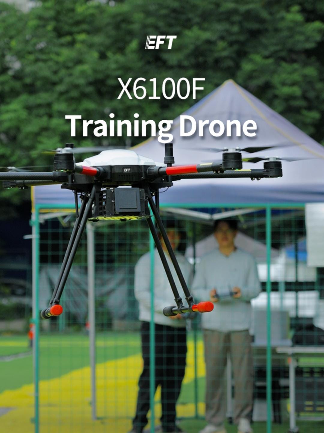
When 14 m/s Winds Hit, the X6100F Doesn’t Blink

Most training drones look great in a calm parking lot. The real question is what happens when the wind picks up mid-lesson — because on a real training field, it always does. That’s exactly why we put the EFT X6100F through full wind-tunnel testing before it ever reached a trainee’s hands.

https://www.youtube.com/shorts/XY-QPz1Q0qM

Inside the tunnel, the numbers tell the story. The minimum safe wind-resistance benchmark was set at a steady 7.9 m/s (Level 4 wind) — the point at which an inexperienced pilot, without a stabilized platform, would already start losing confidence and control. The X6100F didn’t just meet that bar; testing pushed the aircraft all the way to 14 m/s, Level 7 wind, with the drone holding a stable hover in front of the tunnel gate the entire time. That’s the kind of margin you want between “textbook conditions” and “the actual weather on training day.”

What makes that possible isn’t luck — it’s the hardware underneath. The X6100F is built around our brand-new N1 flight controller, tuned specifically for fast, precise stability corrections in gusting conditions, paired with the powerful E5 motor system that delivers the thrust reserve needed to fight crosswinds without sacrificing control response. Together, they turn wind resistance from a spec on a page into something a trainee can actually feel — a platform that stays predictable exactly when it matters most.

Why does this matter so much for training specifically? Because a training drone has one job above all else: build good habits under realistic conditions, safely. A airframe that panics or drifts the moment a breeze picks up doesn’t just slow down the lesson — it teaches the wrong instincts. Instructors need a platform that behaves consistently flight after flight, student after student, so every hour in the air is actually building skill rather than fighting the machine. That’s the standard the X6100F was engineered to hit, and the wind tunnel data backs it up rather than just claiming it.

It’s also worth saying plainly: rock-solid engineering doesn’t have to come with a rock-solid price tag. For flight schools and training academies running fleets across multiple students and multiple sessions a day, the X6100F is built to be one of the best cheap drone options in its class — validated performance without the premium markup, so scaling up a training program doesn’t mean stretching the budget thin.

This kind of testing rigor isn’t a one-off for us. As an industrial drone manufacturer, every airframe we release — whether it’s built for agricultural spraying, industrial inspection, or pilot training — goes through the same demanding validation process before it’s approved to leave the factory. We’d rather find the limits in a controlled wind tunnel than have a customer find them in the field. That commitment to real, verifiable testing is part of why operators and training academies looking for the best drone company to partner with keep coming back to us: not for marketing claims, but for data they can actually check.

For flight academies, agricultural service providers, or enterprise operators building out a training pipeline, the X6100F offers exactly what that first stage of pilot development needs — predictable handling, strong wind tolerance, and hardware tough enough to handle repeated training cycles without performance drop-off. It’s a platform instructors can trust and trainees can learn on with confidence, wind or no wind.

Ready to see the full spec sheet or get a quotation for your training fleet? Send us a message — we’re happy to walk you through configurations that fit your program size and budget.

📩 Message us for full specifications & quotation.

#EFTDrone #X6100F #DroneTraining #PilotAcademy #IndustrialDrone #TrainingDrone #EnterpriseDrone #InspectionDrone #WindTunnelTesting #WindResistance #BestCheapDrone #BestDroneCompany

Read more…

There is a reason aerial video has become such a powerful part of modern content creation. A camera drone can take an ordinary location and instantly give it a sense of scale. A winding mountain road becomes a cinematic line through the landscape. A quiet beach turns into a sweeping coastal scene. Even a simple road trip can feel like the opening sequence of a travel film when viewed from above.

But owning a drone does not automatically guarantee better footage.

Good aerial video comes from the combination of a capable camera, stable flight, thoughtful composition, smooth movements, and knowing when to let the landscape do the work. This is where the IZI Brephos Mini can make a meaningful difference.

Built to make aerial photography and videography more approachable, the Brephos Mini gives creators a compact platform for exploring aerial storytelling. Its combination of camera capabilities, portability, intelligent flight assistance, and user-friendly operation makes it suitable for beginners while giving more experienced creators plenty of creative freedom.

So, how exactly can the IZI Brephos Mini help you capture better aerial videos?

Let’s look at the elements that make the biggest difference.

Start With a Better Perspective

The clearest advantage of a camera drone—and its greatest strength—is the unique perspective it delivers.

A traditional camera keeps you close to the ground. You can change lenses, move around your subject, climb to a viewpoint, or use a tripod, but your perspective is still limited by where you can physically stand.

A drone changes that completely.

With the IZI Brephos Mini, you can move vertically, horizontally, and diagonally through the scene to find perspectives that would be impossible with a handheld camera.

Imagine filming a road through a mountain valley. From the ground, you might capture the road itself. From above, you can show the entire route cutting through the landscape.

That difference in perspective can turn a normal clip into an establishing shot that immediately tells viewers where they are.

Smooth Flight Creates Better Footage

Aerial footage can look impressive even when the subject itself is relatively simple. However, shaky or unpredictable drone movements can quickly ruin an otherwise beautiful shot.

Smooth movement is one of the foundations of cinematic aerial video.

The IZI Brephos Mini is designed to provide a stable and controlled flying experience, helping you maintain smoother movements while recording. For a new pilot, this can be particularly valuable because you can concentrate on framing instead of constantly correcting the aircraft.

Start slowly.

Instead of pushing the controls aggressively, make gradual movements. A slow forward flight toward a subject can feel much more cinematic than rushing toward it. Similarly, slowly pulling away from a location can create a dramatic reveal.

The drone provides the capability, but your control inputs determine the final look.

Use the Drone for Storytelling, Not Just Aerial Shots

One of the easiest mistakes to make when starting with a drone is filling a video with aerial footage simply because it looks cool.

The better approach is to ask yourself what the shot contributes to the story.

Suppose you are making a travel video about a hill station.

You could begin with a close-up of your luggage, cut to footage of the journey, show yourself arriving at the destination, and then use the IZI Brephos Mini for a wide aerial reveal of the mountains.

The aerial shot now has a purpose.

It establishes the environment and gives viewers a sense of scale.

The same principle works for real estate videos, wedding films, outdoor adventures, promotional videos, and documentaries.

A drone should enhance your story rather than distract from it.

Make the Most of Wide Landscapes

The IZI Brephos Mini becomes especially useful when your subject is larger than what a traditional camera can comfortably capture.

India offers countless locations where aerial perspective can add tremendous visual value.

Mountain ranges, beaches, lakes, forests, deserts, agricultural landscapes, waterfalls, and winding roads all benefit from a camera that can move above and around them.

When shooting these environments, avoid trying to include everything in one frame.

Instead, look for a strong visual anchor.

It could be a person standing near a viewpoint, a vehicle moving along a road, a boat crossing a lake, or a building surrounded by open landscape.

Then use the drone's movement to gradually reveal the environment around that subject.

This creates a sense of discovery.

Try the Classic Reveal Shot

The reveal is one of the easiest cinematic drone techniques to learn.

Start with your camera focused on a nearby subject. Slowly move the drone backward or upward, allowing more of the landscape to appear in the frame.

The result is simple but effective.

A person standing on a cliff suddenly becomes part of a much larger mountain landscape. A building is revealed as part of an entire property. A beach gradually expands into a sweeping coastline.

The IZI Brephos Mini makes this type of shot approachable because you do not need advanced piloting skills to begin experimenting with controlled movements.

Once you understand the basics, you can combine vertical and backward movements to create more dynamic reveals.

Experiment With Orbit-Style Shots

Another popular aerial technique is an orbit.

Instead of flying directly toward or away from a subject, the drone moves around it while keeping the subject within the frame.

This can create an engaging sense of movement and depth.

For beginners, it is best to start slowly and use an open environment. Choose a clear subject and maintain a safe distance from obstacles.

An orbit can work beautifully around people, vehicles, buildings, viewpoints, and natural landmarks.

With practice, you can make the movement smoother and more consistent, giving your videos a much more polished appearance.

Golden Hour Can Transform Your Footage

Good equipment helps, but lighting remains one of the biggest factors in photography.

The IZI Brephos Mini can give you a new perspective, but choosing the right time to fly can make that perspective dramatically better.

Golden hour, shortly after sunrise or before sunset, is particularly useful for aerial photography.

The low angle of the sun creates longer shadows, warmer tones, and greater depth across the landscape. Mountains develop more visible textures, buildings catch warmer light, and landscapes can appear more dimensional.

Early morning can also offer quieter locations and softer light.

If you are planning a dedicated shoot, consider checking the sunrise and sunset timing beforehand and reaching the location early enough to prepare.

Sometimes the difference between an average drone shot and an exceptional one is simply the time of day.

Keep Your Movements Deliberate

Fast drone movements can be fun to perform, but they are not always effective on camera.

Aerial filmmaking generally benefits from deliberate movement.

Try moving at a consistent speed rather than constantly accelerating and slowing down. Avoid sudden changes in direction unless the shot specifically requires them.

You can also use pauses.

For example, let the drone hover briefly before beginning a slow reveal. This gives the viewer a moment to understand the frame before the movement begins.

Think of the drone as a moving camera rather than an aircraft you are simply trying to steer.

That mindset can significantly improve your footage.

Use Foreground Elements to Add Depth

Aerial videos can sometimes look flat because everything is far away.

One way to solve this is by introducing foreground elements.

Trees, rocks, buildings, walls, roads, or other objects can sit between the camera and the main subject. As the drone moves, the foreground passes through the frame while the background remains visible.

This creates depth and makes the footage feel more three-dimensional.

The compact nature of the IZI Brephos Mini gives creators plenty of flexibility when finding these compositions.

Instead of always flying high above everything, experiment with different heights and distances.

You may be surprised by how cinematic a relatively low-altitude shot can look when the composition is right.

Use Movement to Reveal Scale

One of the greatest strengths of aerial filming is the ability to show scale.

A person standing beside a mountain is visually different from a person standing within a huge mountain landscape.

The drone allows you to gradually transition between these perspectives.

Start relatively close to your subject and slowly move away.

As the drone retreats, the surrounding landscape begins to dominate the frame. The viewer understands not only what the subject looks like, but where the subject exists within the environment.

This technique works particularly well for travel content.

A single pull-back shot can communicate the scale of a destination far more effectively than several ground-level clips.

Don't Always Fly High

There is a common assumption that the best drone footage comes from flying as high as possible.

That is not necessarily true.

High-altitude shots are useful for establishing scale, but lower shots can provide stronger visual detail.

Try flying at different heights and see how the composition changes.

At a lower altitude, you might capture road textures, architectural details, waves, trees, or moving subjects more clearly.

At a higher altitude, the same location may become an abstract pattern.

The best height is the one that serves the shot.

Use Intelligent Features as a Creative Starting Point

For new drone users, manually controlling every movement can be challenging.

Intelligent flight features can help simplify the process and give beginners an opportunity to experiment with cinematic movements.

The IZI Brephos Mini provides flight assistance and smart features designed to make aerial filming more accessible.

Instead of treating these features as a replacement for piloting skills, think of them as a learning tool.

Use them to understand how different movements affect your footage. Once you become comfortable, begin recreating similar shots manually.

Over time, your understanding of drone movement will naturally improve.

Plan Your Shots Before You Take Off

Battery life is limited, and good lighting windows can be even shorter.

Planning your shots before launching the drone can make your filming session significantly more productive.

Think about three things:

Where should the drone start?

Where should it finish?

What should the camera reveal during the movement?

You can even visualize the sequence before taking off.

For example, you might decide to start behind a building, rise slowly above it, and reveal a mountain range in the background.

Once you know the shot, flying becomes much easier.

This is particularly useful when you are traveling and only have a few minutes at a location.

Capture More Than One Version of a Shot

Even experienced filmmakers rarely rely on one take.

If time and battery allow, capture variations.

Try the same movement at different speeds. Change your altitude slightly. Experiment with the camera angle. Try moving in the opposite direction.

You may discover that the shot you originally imagined is not the best version.

Because the IZI Brephos Mini is designed to be easy to carry and quick to deploy, it can be particularly convenient for capturing multiple creative options during a travel or outdoor shoot.

Think About the Editing Before You Fly

Better aerial video is not just about what happens in the sky.

Think about how your drone footage will connect with your other clips.

A wide aerial establishing shot can work beautifully at the beginning of a sequence. A slow reveal can transition from a close-up to a landscape. A top-down shot can create a visual break between two locations.

You can also match movement.

If your handheld camera moves from left to right, consider using a drone shot with a similar direction. Small details like this can make the final edit feel more intentional.

The drone gives you another camera angle. Editing determines how effectively you use it.

Keep the Composition Simple

Aerial scenes can contain enormous amounts of visual information.

That does not mean your frame needs to contain everything.

Look for clean shapes, strong lines, symmetry, patterns, and clear subjects.

Roads, rivers, coastlines, bridges, fields, and buildings can all create natural leading lines.

If there is a single subject you want viewers to notice, give it enough visual space.

A clean composition often looks more impressive than a complicated one.

Why the IZI Brephos Mini Makes Aerial Filming Easier

The real advantage of the IZI Brephos Mini is that it brings several useful elements together.

Its compact design makes it convenient to carry. Its camera gives creators the ability to capture aerial perspectives for photography and video. Its flight assistance makes the learning curve more approachable, while intelligent features provide additional creative possibilities.

That combination makes it suitable for a wide range of users.

A beginner can use it to learn the fundamentals of drone flying.

A travel creator can use it to add establishing shots to a vlog.

A photographer can experiment with new compositions.

A small business can incorporate aerial footage into promotional content.

An experienced creator can use it as a lightweight addition to an existing camera setup.

The common thread is flexibility.

Aerial Video Is About Technique as Much as Technology

A professional drone can make the process easier, but great footage still comes from the person behind the controls.

Learn to fly smoothly.

Pay attention to light.

Think about composition.

Plan your shots.

Use movement with purpose.

Most importantly, do not be afraid to experiment.

Your first few flights may not produce cinematic masterpieces. That is completely normal. The more you fly, the more naturally you will understand how altitude, speed, direction, camera angle, and light interact.

The IZI Brephos Mini gives you a practical platform on which to build those skills.

Final Thoughts

Capturing better aerial videos is not about flying higher, moving faster, or using every feature available.

It is about seeing the world differently and using movement to communicate that perspective.

The IZI Brephos Mini makes that process more accessible by combining a compact design with capable imaging, stable flight, intelligent assistance, and a straightforward user experience.

For beginners, it provides an approachable way to learn.

For travelers, it adds a powerful camera to the backpack without making the setup unnecessarily complicated.

For content creators, it opens up new possibilities for storytelling.

And for anyone interested in aerial photography, it provides something even more important: the freedom to experiment.

Once you stop thinking of the Brephos Mini simply as a drone and start treating it as a flying camera, its creative potential becomes much clearer. A road, a mountain, a beach, a city, or even an ordinary neighborhood can become an entirely different story when you find the right angle from above.

Read more…

At the WAIC 2026 expo, nearly every embodied AI robot demonstrating real-world tasks was enclosed within a protective barrier. Safety personnel kept their eyes glued to the same vulnerable spots: feet, flanks, and arm trajectories.

These three areas share a fundamental flaw—they all lie outside the FOV of the head-mounted primary camera, occluded by the robot’s own body.

This is not a limitation of AI model capacity. Even the most advanced end-to-end model cannot infer spatial physics in areas occluded by the robot’s frame. This is a geometry problem. Yet, for a robot to walk autonomously among humans, it must first master this 5cm-to-1m proximity zone: Is there a drop-off under its feet when stepping forward? Is there a human beside its body when turning around?


The industry currently offers multiple approaches, each with distinct trade-offs.

Industry leaders like Tesla and Figure place vision, multimodal AI, and end-to-end learning at the core of their control architecture, attempting to use a unified neural network to handle all sensing and execution. While this approach offers indisputable value in scene understanding and generalizability, it fails to address two critical bottlenecks: body-occluded blind spots, and the massive compute overhead required for high-frequency, low-semantic spatial judgments (“Is an object nearby, and how far is it?”).


Thus, the architecture shifts toward a division of labor: The AI model handles high-level understanding and task planning, while an independent ranging pipeline guards the safety baseline at close range. Based on this deterministic input, low-level controllers handle real-time deceleration, evasion, or emergency stops.

This independent safety pathway features a shorter execution loop, predictable response latency, and easily quantifiable failure modes—making it vastly easier to benchmark, validate, and certify for mass-production acceptance.

Read more…

Modern drones are becoming increasingly autonomous.

From precision landing and terrain-following flight to industrial inspection and mapping missions, UAV systems require accurate environmental perception to make reliable decisions.

While GPS, barometers, optical flow cameras, and ultrasonic sensors are commonly used for altitude and positioning, each technology has limitations in certain environments.

For many drone applications, a laser rangefinder sensor provides a practical solution by delivering fast, accurate, and non-contact distance measurements.

This article explains:

  • Why UAV systems need laser distance measurement
  • How laser rangefinder sensors work
  • How to choose the right distance sensor for drones
  • Key considerations when integrating a sensor with ArduPilot or PX4 systems

Why Do Drones Need Laser Rangefinder Sensors?

A drone's flight controller relies on multiple sensors to estimate position and movement.

Common sensors include:

SensorAdvantagesLimitations
GPSLong-range outdoor positioningLimited accuracy near obstacles or indoors
BarometerSimple altitude estimationAffected by weather and pressure changes
Optical FlowGood for low-altitude stabilizationDepends on ground texture and lighting
Ultrasonic SensorLow costLimited range and environmental adaptability
Laser RangefinderAccurate distance measurementRequires proper target conditions

For autonomous UAV applications, knowing the exact distance between the drone and surrounding objects is critical.

Typical applications include:

  • Autonomous landing
  • Low-altitude hovering
  • Terrain-following flight
  • Obstacle detection
  • Industrial inspection
  • Drone mapping

Unlike GPS, which estimates absolute position, a laser rangefinder directly measures the physical distance between the sensor and a target surface.

This makes it especially useful when drones operate close to the ground or in environments where GPS signals are unreliable.


How Do Laser Rangefinder Sensors Work in UAV Applications?

Most drone laser distance sensors use one of two measurement principles:

1. Time-of-Flight (ToF) Measurement

Time-of-Flight technology calculates distance by measuring how long a laser pulse takes to travel to an object and return to the receiver.

The basic principle is:

Distance = Light Speed × Flight Time ÷ 2

Because the speed of light is extremely fast, precise timing circuits are required to measure very small time differences.

ToF technology is commonly used for:

  • Long-distance UAV measurement
  • Outdoor applications
  • Target ranging
  • Autonomous navigation

For example, Meskernel's TS1224 laser rangefinder module uses pulse ToF technology and provides long-distance measurement capability with a compact form factor.

The module supports:

  • 5–1500m / 2000m / 2500m measurement ranges
  • ±1m accuracy
  • UART / RS485 / RS232 communication interfaces

This type of sensor is suitable for UAV platforms requiring long-range distance measurement with lightweight integration.


2. Phase-Shift Measurement

Phase-based laser distance sensors calculate distance by analyzing the phase difference between transmitted and received laser signals.

Compared with pulse ToF sensors, phase measurement is often used when applications require:

  • Higher precision
  • Stable short-to-medium distance measurement
  • Industrial automation integration

Compact phase laser modules are widely used in robotics, automation equipment, and UAV payload systems where accurate distance feedback is required.

Meskernel phase laser distance modules support compact integration and multiple communication interfaces including UART, RS485, RS232, and Modbus options depending on the model.


Key UAV Applications of Laser Distance Sensors

1. Precision Drone Landing

Automatic landing is one of the most common applications for drone rangefinder sensors.

During landing, GPS accuracy may not be sufficient to determine the exact height above the landing surface.

A downward-facing laser rangefinder can continuously measure:

  • Distance to the ground
  • Landing height
  • Descent speed

The flight controller can then adjust:

  • Motor output
  • Descent speed
  • Hover position

This improves landing reliability, especially when operating on uneven terrain or near obstacles.


2. Terrain Following Flight

Terrain-following drones must maintain a stable altitude while flying over changing landscapes.

Examples include:

  • Agricultural monitoring
  • Mountain inspection
  • Forest surveys
  • Infrastructure inspection

A laser distance sensor provides real-time feedback between the UAV and the ground.

The flight controller can automatically compensate for:

  • Rising terrain
  • Slopes
  • Uneven surfaces

This allows drones to maintain a consistent flight height and improve data collection quality.


3. Drone Mapping and Survey Applications

Mapping drones require stable flight paths and accurate altitude control.

Small variations in flight height can affect:

  • Image overlap
  • Measurement accuracy
  • 3D reconstruction quality

A laser rangefinder can provide additional altitude information to improve mission consistency.

For engineering applications, lightweight laser modules are often preferred because payload weight directly affects:

  • Flight time
  • Battery consumption
  • Overall system efficiency

How to Select a Laser Rangefinder Sensor for a Drone

Choosing a UAV distance sensor requires more than simply selecting the longest measurement range.

Engineers should consider several factors.


1. Measurement Range

Different UAV applications require different distance ranges.

ApplicationTypical Measurement Requirement
Indoor dronesShort range
Precision landingSeveral meters to tens of meters
Industrial inspectionTens to hundreds of meters
Long-range observationHundreds of meters or more

For example:

  • Short-range phase laser sensors are suitable for altitude control and automation systems.
  • Long-range pulse laser rangefinders are better suited for outdoor UAV applications.

Meskernel provides different laser ranging solutions covering compact short-range modules and long-distance UAV rangefinder modules.

Some pulse laser modules support:

  • 100m+
  • 400m+
  • 700m+
  • 1000m+ measurement distances

depending on the model.


2. Weight and Size

Weight is a critical factor for UAV applications.

A heavy sensor can reduce:

  • Flight duration
  • Payload capacity
  • Energy efficiency

Compact laser modules are preferred for drones because they can be integrated into limited installation spaces.

For example, the TS1224 module features:

  • Compact size
  • Approximately 10g weight
  • Low power consumption design

making it suitable for lightweight UAV payload integration.


3. Communication Interface

A UAV distance sensor must communicate reliably with the flight controller or onboard computer.

Common interfaces include:

  • UART
  • I2C
  • RS485
  • CAN

Different UAV platforms may require different protocols.

For example:

  • UART is commonly used for direct flight controller communication.
  • RS485 is useful for industrial UAV systems requiring longer cable distances.
  • CAN is preferred in some distributed robotic systems.

When selecting a sensor, engineers should confirm:

  • Communication protocol
  • Baud rate
  • Data output format
  • Integration requirements

Meskernel provides laser distance modules supporting interfaces such as UART, RS485, RS232, I2C, and Modbus depending on the product model.


Laser Rangefinder vs LiDAR for UAV Applications

Many drone developers compare laser rangefinders with LiDAR systems.

Although both technologies use laser light, they serve different purposes.

 Laser RangefinderLiDAR
Measurement typeSingle distance measurementPoint cloud scanning
System complexityLowerHigher
CostLowerHigher
Integration difficultyEasierMore complex
Typical UAV useAltitude, landing, distance feedbackMapping, 3D environment scanning

For applications such as:

  • altitude measurement
  • landing assistance
  • distance monitoring

a single-point laser rangefinder may provide a simpler and more cost-effective solution.

For applications requiring:

  • 3D mapping
  • environmental reconstruction
  • object recognition

LiDAR may be more suitable.

A detailed comparison of these technologies can be found here:

Laser Rangefinder vs LiDAR:
https://meskernel.net/en/laser-distance-sensor-vs-lidar/


Integrating a Laser Rangefinder with ArduPilot and PX4

For UAV developers, hardware integration is only part of the process.

A typical connection architecture looks like:

 
Laser Rangefinder Sensor          | UART / I2C / CAN          |Flight Controller          |ArduPilot / PX4 System
 

Typical integration steps include:

Step 1: Select the Sensor Interface

Confirm compatibility with:

  • Flight controller
  • Companion computer
  • Communication protocol

Step 2: Install the Sensor

Common installation locations:

  • Bottom of drone frame
  • Front-facing payload mount
  • Gimbal system

Step 3: Configure Parameters

Adjust:

  • Sensor type
  • Communication settings
  • Measurement offset
  • Calibration parameters

Step 4: Validate Flight Data

Test:

  • Altitude readings
  • Response speed
  • Stability during movement

For customized UAV projects, sensor manufacturers with OEM/ODM capability can help adapt:

  • Mechanical dimensions
  • Communication interfaces
  • Firmware requirements

Meskernel provides customized laser ranging solutions for different integration requirements.


Future Trends of Laser Distance Sensors in Autonomous Drones

As drones become more autonomous, distance sensing will continue to evolve.

Future UAV applications will require:

  • Smaller sensor modules
  • Lower power consumption
  • Faster measurement response
  • Better environmental adaptability
  • Easier integration with AI systems

Laser distance sensors will continue to play an important role in:

  • autonomous navigation
  • robotics
  • industrial drones
  • intelligent inspection systems

Final Thoughts

Selecting the right distance sensor is an important decision when designing an autonomous UAV system.

The best sensor depends on:

  • Required measurement range
  • Accuracy requirements
  • Payload limitations
  • Communication interface
  • Operating environment

For drone developers working on:

  • ArduPilot platforms
  • PX4 systems
  • industrial UAVs
  • autonomous robots

a properly selected laser rangefinder sensor can significantly improve:

  • altitude stability
  • landing accuracy
  • navigation reliability

Meskernel develops compact laser distance measurement solutions for UAV, robotics, industrial automation, and smart sensing applications.

Read more…

Hey everyone! If you’re a drone instructor, run a UAV flight school, or are just getting into commercial drone operations, you know how hard it is to find equipment that can withstand the rigors of student pilots while providing a professional experience.📦

https://www.youtube.com/shorts/Y3QVeYWgYmw

We just unboxed the EFT X6100F, and it is engineered specifically for training. Here is a quick look at what makes this kit stand out straight out of the box.

What’s in the Box?

As seen in our latest unboxing video, EFT doesn’t cut corners on the presentation and practicality of their training setups.🛠️

  • Ready-to-Assemble Frame: The X6100F features a robust, foldable hexacopter design with striking red and black arms. The folding mechanism makes transport to and from the flying field an absolute breeze.
  • Dual RC MINI Controllers: This is the game-changer for flight schools. The package includes RC MINI controllers, perfect for dual-operator setups (Instructor/Student mode), allowing the trainer to instantly take control if things go sideways.
  • Quality Assurance: Every unit comes with a rigorous product qualification certificate directly from EFT.

Press enter or click to view image in full size

💡 Why Choose EFT for Drone Education?

Finding the right hardware for your curriculum can be tricky. You want something reliable, but you also need to manage your school’s budget. While many beginners might be tempted to start with a cheap training drone, investing in a purpose-built industrial frame saves you money on constant repairs in the long run.

Whether you are looking for a standard training drone for flight simulation, or you need a heavy-duty drone to teach students about payload management, EFT’s modular ecosystem has you covered.

Many instructors in the commercial UAV space consider the EFT ecosystem to provide the best training drone experience because of how closely the flight dynamics mimic heavy industrial rigs. Upgrading your fleet with a versatile training drone means your students are learning on the exact same platforms they will use in the field. Plus, keeping your fleet in the air is simple because replacing parts on your training drone is straightforward and highly accessible.

Hardware. Software. Everything included. Built for learning.

Let us know what you think of the X6100F! What features do you look for most when choosing hardware for your flight school?

#eftdrone #dronetraining #DroneEducation #droneoperator #dronehardware #DroneSoftware #unboxing #droneinstructor #droneschool #commercialdrone

Read more…


1*Mp-BJgeb6DyIHoaGukZ-Wg.jpeg

https://www.youtube.com/shorts/w8-huwFp16g

Looking for a reliable, rock-solid, and hassle-free drone built specifically for pilot training and flight schools? Look no further than the EFT X6100F, engineered by a leading training drone manufacturer dedicated to advancing professional aviation education!

Unlike modified consumer drones, every single detail of the X6100F — from the flight controller and ground station to the dedicated remote control — is fully in-house developed and engineered strictly for training purposes. If you are searching for a high-performance training drone that delivers unmatched reliability in the field, this is the definitive choice.

🔧 Key Features Shown in Action:

  • Quick & Easy Deployment: As seen in the setup process, the X6100F features a portable, foldable design with secure arm locks and fast propeller installation, making field setup a breeze for instructors and students.
  • Rock-Solid Stability: Engineered with a balanced multi-rotor setup (featuring robust motors and clear CCW/CW markings like the E5 system) to ensure stable hovering and predictable handling.
  • High-Visibility Flight Orientation: Designed with contrasting color accents (sleek black body with high-visibility red arm highlights) to help students easily track orientation during line-of-sight training.
  • Dedicated Remote Control: Comes with a custom-designed, ergonomic remote control featuring responsive joysticks and clearly labeled switches for effortless, fatigue-free flying during long training sessions.
  • Precision Control & Agility: Whether executing tight maneuvers between cones or performing steady aerial positioning, the flight controller delivers smooth and responsive flight dynamics.

🌐 Why Choose the EFT X6100F?

  • 100% In-House Ecosystem: Seamless integration between the drone, flight controller, and ground station from an experienced training drone manufacturer.
  • Built for Endurance: Lightweight yet durable structure designed to withstand the rigorous demands of daily flight school operations.
  • Safe & Beginner-Friendly: Predictable flight behavior helps boost student confidence quickly, making it widely recognized as a hot sale training drone in global markets and consistently rated by instructors as the best training drone for academy environments.

Are you a flight school owner, instructor, or drone training provider looking to upgrade your fleet? Let’s connect in the comments below, or reach out to us to learn more about how the X6100F can elevate your training programs!

#EFTDrone #X6100F #TrainingDrone #DroneCourse #LightweightDrone #DroneManufacturer #DroneFactory #AsiaHotsaleDrone #DroneTraining #FlightSchool

Read more…

In 2022, a smart pool-cleaning robot project was quietly launched on Kickstarter. Back then, no one called smart pool robotics an "industry sector"—it was just a niche, forgotten branch within consumer robotics.

Four years later, in 2026, this product category stands on the precipice of crossing the chasm: mainstream flagship models from leading OEMs ship millions of units annually; the world's first flagship model powered by a 360° underwater LiDAR debuted its mass-production version in late 2025; and the category has taken center stage at major trade platforms like Black Friday (North America), PSP Expo, and CES.

Throughout these four years, Benewake’s underwater LiDAR has never missed a beat. From early crowdfunding exploration to mass-market volume supply, and onto world-first flagship integration—Benewake has partnered with the pool robotics industry through a complete cycle.

This story is about that journey.

I. Three Types of Vendors vs. One Full-Cycle Partner

Across the aquatic robotics sensing market, suppliers generally fall into three categories:

  • Type 1: "Accidental Off-the-Shelf Fit"
  • Type 2: "Opportunistic Hype Followers"
  • Type 3: "Full-Cycle Co-Builders"

These three types represent vastly different capability ceilings. The first delivers a single part with zero customization. The second delivers once, becoming unresponsive when next-gen platforms demand innovation. Only the third category can navigate a complete industry cycle alongside its customers.

Very few suppliers across the global industry can check all four boxes: Pre-Research, Engineering Breakthrough, Mass Production, and Real-World Field Execution.

II. Four Products = Four Milestones of a Full Cycle

This classification is grounded in reality. Laying out Benewake’s roadmap over the past four years reveals a clear, step-by-step trajectory.

Phase 1 · What sensors can actually work underwater? (2022–2024)

Before 2022, pool robots relied heavily on mechanical bumpers and acoustic sensors. However, ultrasonic sensors frequently fail at steep angles or pool corners, while optical vision collapses in murky water. At the time, the entire industry was stuck on a foundational question: Besides sonar, what sensor can survive underwater?

Benewake's strategic thesis was clear: The bottleneck in underwater perception isn't algorithms—it's optoelectronic components. Over the past decade, massive demand for smartphone ToF and automotive LiDAR drove the single-photon avalanche diode (SPAD) chip supply chain to maturity—reaching a consumer-grade mass-production tipping point around 2023.

In August 2024, the first unit of the Benewake TF-Luna Underwater Edition shipped—transitioning underwater LiDAR from "theoretically feasible" to "manufacturable and commercially viable."

Early customer feedback was raw and straightforward: "Can you reach 20 meters? 10 meters? What about at 10 NTU turbidity?"

"Entering a completely uncharted industry, early customers didn't know their exact LiDAR specs. You must first optimize a mature architecture for underwater deployment and bring costs down. Only when they deploy it can feedback flow in, cognitive models iterate, requirements consolidate, and purpose-built underwater generations be solidly engineered."

Phase 2 · How good is "good enough" for real-world deployment? (2024–2025)

In the year following the first shipment, customer feedback poured in: U-shaped pool floors stretched range limits; bright sunlight, low-reflectivity surfaces, mirrored tiles, and murky water presented complex optical challenges on OEMs' testing tables.

Benewake responded by clearing multiple hurdles simultaneously: Performance, Cost, and Mass-Production Yield Stability.

In October 2025, the TF-UW500 entered mass production—delivering the industry's first perception solution capable of full-coverage residential pool mapping.

The ramp-up phase was intense: meeting North American Black Friday delivery windows meant scaling monthly capacity from prototype builds to tens of thousands of units within four months.

"When the UW500 rolled off the line, we realized what flagship customers were really buying. It wasn't just 5 meters in clear water—it was the engineering headroom to eliminate corner cases."

Phase 3 · OEMs entrust us with frontier customization (2025–2026)

Following the mass production of the UW500, customer demands evolved from edge mapping to full-environment 3D mapping. Freeform pools, kidney-shaped layouts, and multi-tier depth transitions required flagship models to construct real-world 3D spatial awareness underwater.

This presented a significant engineering leap: expanding single-point sensing into a 360° omni-directional rotating scan while maintaining long-term waterproof and operational stability underwater. Tier-1 OEMs entrusting this exploratory customization to Benewake was the direct result of trust built over the preceding two years.

Thus, the VLS-H5 was born—the industry's first 360° omni-directional underwater LiDAR integrated into mass-produced pool robots.

A common industry misconception is that the VLS-H5 is simply an "upgraded" UW500. In reality, both lines share a unified platform architecture—the UW500 single-point engine serves as the underlying technology stack for the VLS-H5's rotating assembly. Flagship robots often integrate both to deliver multi-layered perception.

"The VLS-H5 isn't an upgrade to the UW500; it's its sibling. One handles long-range forward perception, the other handles full spatial coverage. OEMs deploy them in tandem based on algorithmic needs."

Phase 4 · Proactive Market Penetration (2026)

Immediately following flagship mass production, Benewake launched its value-tier lineup—a move that defies conventional hardware logic. Most players prefer to maximize margins at the high end before entering price wars. But consumer robotics follows a different rhythm: mainstream market adoption doesn't happen automatically; upstream component makers must deliver cost-optimized solutions first to unlock the market.

Benewake's two value-tier offerings target the two largest segments of the end market:

文章内容
  1. TF-UW300 (3m Underwater Single-Point): Engineered for standard residential pools, freeing mid-tier models from paying a premium for unnecessary 5-meter range redundancy.
  2. TF-UW150 (1.5m Underwater Single-Point): Brings underwater LiDAR to entry-level price points for the first time, empowering budget models to tackle curved pool floors and edge cases that traditional ultrasonics fail to solve.
"The market doesn't mature on its own before we build value models—the market matures because we build value models. Reaching high-end benchmarks proves capability; building what the market needs reflects pragmatism; doing both at scale proves comprehensive strength."

Three years, four products. Over the past year alone, Benewake has shipped over 100,000 single-point underwater LiDAR units to global pool-cleaning robot OEMs. Every entry in today's "Full Portfolio" is battle-tested—built to deliver tangible value to both robot manufacturers and end users.

III. Back to 2022

Looking back at that Kickstarter machine in 2022, no one called smart pool robotics a dedicated industry sector. Today, the category stands at the tipping point of crossing the chasm. Through every step of these four years, Benewake's underwater LiDAR has been an active participant.

Building a "Full Portfolio" was never the ultimate goal—it is simply the tangible proof of years spent deeply rooted in the industry.

"A product portfolio is not a target; it is a result. Looking back, every footprint is a product we built—reflecting our evolving insights alongside our customers at every stage of market maturity. On this journey of exploration, Benewake remains committed to moving forward together with the entire industry..."
Read more…

While consumer robotics frequently make headlines with humanoid form factors and futuristic drones, a quieter revolution is taking place beneath the surface. Pool cleaning robots have quietly emerged as the most commercially mature and steady champions of the consumer robotics race. Today, Chinese solid-state LiDAR pioneer Benewake has unlocked the next generation of underwater mobility with the commercial launch of its VLS-H5—the world's first mass-produced 360° underwater omnidirectional scanning LiDAR designed specifically to bring precise spatial awareness to extreme aquatic environments.

For years, underwater perception has remained a notorious challenge for hardware engineers. Unlike land-based robots, underwater platforms must grapple with intense sunlight reflections at the water’s surface, optical refraction from wave ripples, and severe signal scattering caused by organic debris. By launching the VLS-H5, Benewake directly addresses these physics-bound limitations, allowing pool cleaning robots to transition from blind, randomized scrubbing to highly precise, centimeter-level path planning.

First Commercial Adoption: The MOVA Rover X10

Demonstrating the immediate commercial viability of this technology, robotic innovator Surge Future has integrated the VLS-H5 into its newly unveiled flagship product: the MOVA Rover X10.

Equipped with enhanced vertical propulsion, the Rover X10 operates like an underwater drone, navigating autonomously along three axes—ascending, hovering, descending, and moving horizontally. Powered by Benewake's LiDAR-driven SLAM algorithm, the Rover X10 abandons primitive boundary-following logic. Instead, it generates a comprehensive, real-time spatial map of complex pools, capturing curved steps, variable depths, and sharp corners with accuracy that easily outclasses traditional sonar or camera-only alternatives.

文章内容

Engineered for Extremes: Three Core Capabilities

The VLS-H5 is not a modified terrestrial sensor; it is a ground-up optical solution engineered specifically for harsh underwater environments:

160 KLux Light Immunity: Standard optical sensors suffer from receiver saturation when exposed to the intense midday sun in tropical or low-latitude markets, where ambient light routinely exceeds 100 KLux. The VLS-H5 handles up to 160 KLux of light exposure, maintaining stable point-cloud outputs even under direct, harsh summer sunlight.

Penetrating Water Turbidity: Using a Class 1 eye-safe visible light source, the sensor delivers a range of over 5 meters in clear water (covering up to 78 m² in a single scan). In highly turbid water (NTU ≤ 4), it consistently maintains a detection range of ≥1.5 meters with an accuracy margin of under 3 centimeters.

Compact and Hardened Architecture: Measuring just 75 × 52 × 53 mm, the sensor fits seamlessly into the tightly constrained 5-to-10 cm depth envelopes of modern robots. Rated IPX8, the VLS-H5 operates continuously at depths of up to 4 meters, protected by specialized anti-UV, anti-corrosion materials, and high-transmittance optical coatings.

Shifting from Passive Automated to Genuinely Intelligent Cleaning

The integration of the VLS-H5 changes how a pool robot interacts with its environment. Leveraging a 360-degree sweep at a 6 Hz refresh rate, the mapping process is nearly instantaneous. Users no longer have to wait for the robot to slowly trace every edge of the pool before generating a layout on their mobile app; instead, a complete, highly accurate map is rendered almost immediately.

Furthermore, the VLS-H5 keeps blind spots under 10 centimeters. By continuously monitoring distances to walls and obstacles, the robot dynamically plans paths around toys or structural elements, decelerating smoothly and cleaning tight edges without aggressive, structural-damaging collisions. If interrupted, the robot resumes its path with millimeter-level memory, avoiding repetitive cleaning and minimizing energy consumption.

Executive Perspectives

"We have established highly mature manufacturing and delivery pipelines for pool-robotic LiDAR systems," said Dr. Yuan Li, CEO of Benewake. "The VLS-H5 underwater 360° omnidirectional scanner has officially achieved mass production with its debut on the MOVA series, and we look forward to rolling out more specialized sensors in the near future."

"Our strategic partnership with Benewake marks a major leap forward in intelligent underwater perception," noted Lei Huang, President of Surge Future & Global Head of MOVA. "Benewake's robust LiDAR technology equips our robots with peerless spatial awareness. This collaboration allows us to deliver a faster, smarter, and entirely hands-free pool cleaning experience, pushing the boundaries of what consumers can expect."

About Benewake

Benewake is a leading deep-tech company focused on "building the eyes for autonomous machines" and establishing the sensory infrastructure for physical AI. Founded and led by a distinguished executive team of PhDs—including CEO Dr. Yuan Li (alumnus of Wake Forest University, mentored by Dr. Xurong Xu, a pioneer of Chinese luminescence physics) and CTO Dr. Da Shu (alumnus of Université Paris-Saclay)—the company is bringing automotive-grade reliability to diverse robotics fields. Today, Benewake is one of the world's leading suppliers of pool-cleaning LiDAR systems, driving high-performance spatial awareness across outdoor mowing, embodied AI, and global logistics networks.

Read more…

While consumer robotics frequently make headlines with humanoid form factors and futuristic drones, a quieter revolution is taking place beneath the surface. Pool cleaning robots have quietly emerged as the most commercially mature and steady champions of the consumer robotics race. Today, Chinese solid-state LiDAR pioneer Benewake has unlocked the next generation of underwater mobility with the commercial launch of its VLS-H5—the world's first mass-produced 360° underwater omnidirectional scanning LiDAR designed specifically to bring precise spatial awareness to extreme aquatic environments.

For years, underwater perception has remained a notorious challenge for hardware engineers. Unlike land-based robots, underwater platforms must grapple with intense sunlight reflections at the water’s surface, optical refraction from wave ripples, and severe signal scattering caused by organic debris. By launching the VLS-H5, Benewake directly addresses these physics-bound limitations, allowing pool cleaning robots to transition from blind, randomized scrubbing to highly precise, centimeter-level path planning.

First Commercial Adoption: The MOVA Rover X10

Demonstrating the immediate commercial viability of this technology, robotic innovator Surge Future has integrated the VLS-H5 into its newly unveiled flagship product: the MOVA Rover X10.

Equipped with enhanced vertical propulsion, the Rover X10 operates like an underwater drone, navigating autonomously along three axes—ascending, hovering, descending, and moving horizontally. Powered by Benewake's LiDAR-driven SLAM algorithm, the Rover X10 abandons primitive boundary-following logic. Instead, it generates a comprehensive, real-time spatial map of complex pools, capturing curved steps, variable depths, and sharp corners with accuracy that easily outclasses traditional sonar or camera-only alternatives.

文章内容

Engineered for Extremes: Three Core Capabilities

The VLS-H5 is not a modified terrestrial sensor; it is a ground-up optical solution engineered specifically for harsh underwater environments:

160 KLux Light Immunity: Standard optical sensors suffer from receiver saturation when exposed to the intense midday sun in tropical or low-latitude markets, where ambient light routinely exceeds 100 KLux. The VLS-H5 handles up to 160 KLux of light exposure, maintaining stable point-cloud outputs even under direct, harsh summer sunlight.

Penetrating Water Turbidity: Using a Class 1 eye-safe visible light source, the sensor delivers a range of over 5 meters in clear water (covering up to 78 m² in a single scan). In highly turbid water (NTU ≤ 4), it consistently maintains a detection range of ≥1.5 meters with an accuracy margin of under 3 centimeters.

Compact and Hardened Architecture: Measuring just 75 × 52 × 53 mm, the sensor fits seamlessly into the tightly constrained 5-to-10 cm depth envelopes of modern robots. Rated IPX8, the VLS-H5 operates continuously at depths of up to 4 meters, protected by specialized anti-UV, anti-corrosion materials, and high-transmittance optical coatings.

Shifting from Passive Automated to Genuinely Intelligent Cleaning

The integration of the VLS-H5 changes how a pool robot interacts with its environment. Leveraging a 360-degree sweep at a 6 Hz refresh rate, the mapping process is nearly instantaneous. Users no longer have to wait for the robot to slowly trace every edge of the pool before generating a layout on their mobile app; instead, a complete, highly accurate map is rendered almost immediately.

Furthermore, the VLS-H5 keeps blind spots under 10 centimeters. By continuously monitoring distances to walls and obstacles, the robot dynamically plans paths around toys or structural elements, decelerating smoothly and cleaning tight edges without aggressive, structural-damaging collisions. If interrupted, the robot resumes its path with millimeter-level memory, avoiding repetitive cleaning and minimizing energy consumption.

Executive Perspectives

"We have established highly mature manufacturing and delivery pipelines for pool-robotic LiDAR systems," said Dr. Yuan Li, CEO of Benewake. "The VLS-H5 underwater 360° omnidirectional scanner has officially achieved mass production with its debut on the MOVA series, and we look forward to rolling out more specialized sensors in the near future."

"Our strategic partnership with Benewake marks a major leap forward in intelligent underwater perception," noted Lei Huang, President of Surge Future & Global Head of MOVA. "Benewake's robust LiDAR technology equips our robots with peerless spatial awareness. This collaboration allows us to deliver a faster, smarter, and entirely hands-free pool cleaning experience, pushing the boundaries of what consumers can expect."

About Benewake

Benewake is a leading deep-tech company focused on "building the eyes for autonomous machines" and establishing the sensory infrastructure for physical AI. Founded and led by a distinguished executive team of PhDs—including CEO Dr. Yuan Li (alumnus of Wake Forest University, mentored by Dr. Xurong Xu, a pioneer of Chinese luminescence physics) and CTO Dr. Da Shu (alumnus of Université Paris-Saclay)—the company is bringing automotive-grade reliability to diverse robotics fields. Today, Benewake is one of the world's leading suppliers of pool-cleaning LiDAR systems, driving high-performance spatial awareness across outdoor mowing, embodied AI, and global logistics networks.

Read more…

https://www.youtube.com/watch?v=DJKyTlXO-wQ

If you’ve ever been curious about what makes an agricultural drone strong enough to handle thousands of hectares of spraying missions, a complete teardown is one of the best ways to understand its engineering.

In this video, EFT’s in-house R&D technicians walk through a complete disassembly of the Z80, removing each major component step by step — from the spraying system and landing gear to the structural modules and internal connections — revealing how a modern agricultural drone is built for strength, maintenance, and long-term reliability. This process isn’t just about taking a drone apart; it’s an opportunity to learn about the design philosophy behind professional agricultural drones.

Disclaimer: This video shows professional maintenance procedures carried out by experienced technicians. It is for educational purposes only. Never try to disassemble a drone while it is in operation without having received professional training and safety measures.

One of the first things that becomes clear during the teardown is the use of modular construction. Instead of having components that are permanently fixed, the Z80’s aluminum metal truss frame — engineered with a triple safety factor to handle full-load flight stress — is made up of separate structural sections that can be removed individually via a quick-release module system. This approach greatly reduces maintenance time and allows for damaged parts to be replaced without rebuilding the entire aircraft.

As the disassembly continues, viewers can clearly see how the agricultural drone frame serves as the main structure of the entire aircraft. Every mounting position, support bracket, and fastening point is engineered to hold heavy loads while keeping the drone balanced during flight. Pulling the 80-liter spray tank reveals the internal baffle structure built into its anti-surge design — the feature responsible for reducing liquid sloshing mid-flight, which is one of the more common causes of unstable handling in lower-quality spraying drones. Spraying drones often work in environments with vibration, dust, humidity, and chemical exposure, so structural stability is as important as flight performance.

Another interesting feature is how the wiring, spray components, and power modules are arranged inside the drone frame. Disassembling the spraying system exposes the dual flexible-impeller pumps and centrifugal nozzles that drive the Z80’s 36L/min flow rate — components chosen specifically for their resistance to wear and chemical corrosion after repeated exposure to fertilizers and pesticides. Instead of making things more complicated, the internal layout keeps essential systems easy to inspect and service. This practical design helps reduce downtime for commercial users and simplifies routine maintenance after a busy spraying season.

The video also shows the removal of structural arms, landing gear, mounting brackets, and spray systems, giving viewers a better understanding of how professional drone manufacturers design for easy field serviceability. Every bolt, connector, and joint has a purpose, balancing weight reduction with mechanical strength.

For engineers, drone enthusiasts, and maintenance technicians, watching a full teardown offers valuable insight. Agricultural drones need to carry much heavier loads, withstand repeated takeoffs and landings, and stay stable during low-altitude precision spraying. These demanding applications require reinforced materials, optimized load distribution, and highly rigid structural designs.

Many people who are interested in building their own agricultural drones often ask if it’s practical to create their own platform. Studying professional designs is a great starting point. Understanding how commercial DIY drone frames are reinforced, assembled, and serviced can help builders avoid common structural mistakes and improve safety and reliability.

The teardown also highlights several characteristics common among experienced drone frame manufacturers. Quality manufacturers don’t only focus on looks — they prioritize corrosion resistance, modular maintenance, vibration reduction, structural rigidity, and long service life. These engineering details may not be obvious from the outside, but they become clear once the aircraft is completely disassembled.

As agricultural operations continue to grow globally, there is increasing demand for reliable large-sized drone frame solutions that can carry larger tanks, wider spraying systems, and more powerful propulsion setups. Modern frame design is moving toward lighter materials, better structural efficiency, and faster maintenance cycles, helping operators reduce downtime during busy farming seasons.

Whether you’re an agricultural drone operator, UAV technician, distributor, or simply interested in drone engineering, a complete teardown offers knowledge that you can’t learn from product photos alone. Seeing how every structural component fits together gives a deeper appreciation of the engineering behind today’s professional agricultural drones.

🔥 Watch the full teardown and explore the internal engineering of a professional agricultural drone.

Have questions about frame structure, maintenance, or drone manufacturing? Check out the full Z80 specifications or reach out directly — we’re always happy to discuss agricultural drone technology with fellow UAV enthusiasts.

Follow for more professional drone knowledge and engineering insights:
https://www.effort-tech.com/en/z80

Read more…

Synerobotics

Nov 12 2023 and Jun 2024 presented a new chapter in Marine Ecology monitoring in the Philippines

With Synerflight Lauching its official Prototype touring USV  its first maiden was on Cordova CEBU Protected Area

Pack with the Synerduino system and Imaging equipment design to Visualy map out the Sea floor on shallow coast.

Blue Loop Initiative

Synerflight is one of the consortium of the blue loop program along side other notable developments. in bringing awarness to our marine resources.

31198396657?profile=RESIZE_710x

31198396092?profile=RESIZE_710x

31198396256?profile=RESIZE_710x

31198395070?profile=RESIZE_710x


31198393680?profile=RESIZE_710x


31198394454?profile=RESIZE_710x


https://synerflight.com/2023/11/19/aqua-nimbus-synerflight-usv-first-mission/

https://synerflight.com/surface-system/

Read more…

How Laser Ranging Sensors Improve UAV Altitude Control and Autonomous Flight Performance

Modern UAVs are becoming increasingly autonomous.

From agricultural drones and inspection platforms to delivery drones and robotics systems, accurate environmental perception has become one of the biggest challenges in drone development.

GPS provides positioning.

IMU provides motion information.

Barometers estimate altitude.

However, none of these sensors directly answer one important question:

How far is the drone from the object below or around it?

This is where a laser ranging sensor becomes valuable.

By measuring distance directly using laser technology, UAV developers can improve altitude stability, terrain following, obstacle detection, and autonomous navigation performance.


What Is a Laser Ranging Sensor?

A laser ranging sensor is a distance measurement device that uses laser light to determine the distance between the sensor and a target.

Unlike cameras that require image processing or ultrasonic sensors that have limited range, laser-based measurement provides direct distance information with high accuracy and fast response.

A typical laser ranging sensor consists of:

  • Laser transmitter
  • Optical receiver
  • Signal processing unit
  • Distance calculation algorithm
  • Communication interface

For UAV integration, the sensor is usually designed as a compact laser module or laser distance module that can connect directly with a flight controller or onboard computer.


How Laser Distance Measurement Works in UAV Systems

Most UAV laser distance sensors use Time-of-Flight (ToF) technology.

The measurement process:

  1. The laser module emits a pulse toward the target.
  2. The reflected signal returns to the receiver.
  3. The sensor calculates the travel time.
  4. The distance data is transmitted to the flight controller.

This allows the UAV system to continuously understand its relative distance from the environment.

A simplified architecture:

 
Laser Distance Module        ↓UART / RS232 / RS485        ↓Flight Controller        ↓Altitude Control Algorithm        ↓Motor Adjustment


 The performance of a UAV distance sensor depends on several factors, including wavelength selection, measurement method, optical design, and signal processing algorithms. A deeper understanding of Laser Distance Measurement Technology provides valuable guidance when integrating sensors into autonomous platforms.

Why UAV Developers Need Laser Ranging Sensors

1. More Accurate Altitude Control

Many drones rely on barometers for altitude estimation.

However, atmospheric pressure changes can affect accuracy.

Problems become obvious when flying:

  • Close to the ground
  • Indoors
  • Over uneven terrain
  • During landing

A downward-facing laser distance sensor directly measures the real distance between the UAV and the surface.

Benefits include:

  • More stable hovering
  • Better landing performance
  • Improved low-altitude flight

2. Terrain Following for Autonomous UAVs

Terrain-following drones need continuous altitude adjustment.

For example:

  • Agricultural spraying drones
  • Mapping UAVs
  • Inspection drones

When flying over:

  • Hills
  • Buildings
  • Forest areas

the actual ground distance changes constantly.

A laser ranging sensor provides real-time feedback, allowing the flight controller to maintain a consistent altitude.


3. Obstacle Detection and Collision Avoidance

Autonomous drones need reliable perception.

Compared with camera-only systems, laser distance measurement offers several advantages:

  • Works in low-light environments
  • Provides direct distance information
  • Requires less computing power

A UAV equipped with multiple laser modules can detect:

  • Walls
  • Poles
  • Trees
  • Infrastructure

and react faster.


Choosing the Right Laser Distance Module for UAV Applications

Not every laser sensor is designed for drones.

Engineers should evaluate several important parameters.


1. Size and Weight of the Laser Module

Payload capacity is critical for UAV systems.

A lightweight  allows easier integration into small drones.

For example:

  • Compact dimensions
  • Low power consumption
  • Lightweight structure

are important factors for aerial platforms.

Some Meskernel pulse laser ranging modules are designed for compact integration, with lightweight models around 10g for UAV applications.


2. Measurement Range

Different UAV applications require different sensing distances.

Short-range applications

Examples:

  • Indoor drones
  • Landing assistance
  • Altitude stabilization

Usually require:

  • Several meters
  • Tens of meters measurement range

Long-range UAV applications

Examples:

  • Inspection drones
  • Security monitoring
  • Mapping platforms

require:

  • Hundreds of meters
  • Long-distance detection capability

Meskernel laser ranging solutions include compact modules supporting hundreds of meters to kilometer-level measurement ranges depending on the product design.


3. Communication Interface

For drone developers, sensor integration is often more important than the sensor itself.

A good laser module should support common embedded interfaces:

  • UART
  • RS232
  • RS485

These interfaces allow connection with:

  • PX4 flight controllers
  • ArduPilot systems
  • Raspberry Pi
  • Embedded computers

Meskernel laser distance modules support UART, RS232, RS485 and other communication interfaces for flexible system integration.


4. Measurement Frequency

Flight systems require fast response.

A higher measurement frequency helps improve:

  • Dynamic altitude control
  • Fast obstacle response
  • Real-time position adjustment

For industrial UAV and robotics applications, high-frequency laser sensors can provide faster feedback for control systems.

To better understand the sensor's measurement range, accuracy, communication interfaces, and key technical features, explore our complete collection of product overview videos on YouTube.


Laser Module Options for UAV Developers

Compact Long-Range Laser Modules

For drones with strict payload limitations, compact laser modules are preferred.

Typical advantages:

  • Small footprint
  • Low power consumption
  • Long measurement distance

Example applications:

  • Autonomous drones
  • Robotics platforms
  • Inspection UAVs

Industrial Laser Distance Modules

For professional UAV systems, reliability is essential.

Industrial enclosed laser distance modules provide:

  • Better environmental protection
  • Mechanical stability
  • Easier installation

Some industrial modules support IP-rated protection designs for outdoor applications.


Integrating a Laser Ranging Sensor with ArduPilot and PX4

A typical workflow:

  1. Connect the laser distance module to the flight controller.
  2. Configure communication parameters.
  3. Set sensor orientation.
  4. Calibrate measurement range.
  5. Enable altitude or navigation functions.

After integration, the UAV can use distance data for:

  • Terrain following
  • Landing assistance
  • Obstacle avoidance
  • Autonomous missions

Laser Ranging Sensor vs Camera-Based Distance Measurement

TechnologyAdvantagesLimitations
CameraRich environmental informationRequires complex processing
LiDAR3D perception capabilityHigher cost
Laser ranging sensorLightweight, direct distance measurementUsually measures point distance

For many UAV developers, a laser ranging sensor provides the best balance between:

  • Accuracy
  • Weight
  • Power consumption
  • Integration complexity

Future of Laser Sensors in Autonomous Drones

As UAV systems become more intelligent, sensor requirements will continue to increase.

Future developments include:

  • AI-based navigation
  • Multi-sensor fusion
  • Smaller laser modules
  • Faster distance measurement
  • Autonomous inspection systems

The role of the laser distance module will become increasingly important because autonomous systems depend on accurate environmental perception.


Conclusion

A drone cannot make intelligent decisions without accurate distance information.

GPS tells a UAV where it is.

IMU tells it how it moves.

But a laser ranging sensor tells it how far the world is.

For UAV developers building autonomous drones, robotics systems, and inspection platforms, selecting the right laser distance module can significantly improve flight stability, safety, and performance.

Read more…