Jan Wagner's Posts (3)

Sort by

XL%20Ultrasonic%20Sensor%20Iso_200px.jpgThis is a post about how to receive data from a I2CXL-MaxSonar ultrasonic sensor with RPi's GPIO. Maybe this information can be useful to you or it can save you some time. I am happy for some feedback or optimization proposals etc.


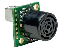
The I2CXL-MaxSonar sensor should be connected to the following RPi GPIO Pins (*):

  • [P1-01]  3.3V -> V+ (Pin 6)
  • [P1-03]  I2C0_SDA -> SDA (Pin 4)
  • [P1-05]  I2C0_SCL -> SCL (Pin 5)
  • [P1-09]  GROUND -> GND (Pin 7)


Before you are able to receive data from the the ultrasonic sensor you have to make sure that I2C-support is enabled within the RPi Linux system settings. You can check one of my previous posts for instructions how to enable it.

You can use the shell commands i2cset and i2cget to test the functionality of your sensor. The default I2C-Address of the sensor is 0x70. To perform a range measurement you must send the "Take Range Reading” command byte 0x51.

# i2cset -y 1 0x70 0x51
# i2cget -y 1 0x70 0xE1 w
0xfd02


A python script can easily be implemented by using the smbus module functions write_byte() and read_word_data(). Finally the two bytes of the returned value need to be swapped because they are received in the wrong byte order.

from smbus import SMBus
from time import sleep

try:
  i2cbus = SMBus(1)
  i2cbus.write_byte(0x70, 0x51)
  sleep(0.12)
  val = i2cbus.read_word_data(0x70, 0xe1)
  print (val >> 8) & 0xff | (val & 0xff), 'cm'
except IOError, err:
  print err


The default I2C-Address of the sensor 0x70 can be changed by overwriting the sensors EEPROM. The sensor requires two separate values 0xAA and 0xA5 to be sent in sequence before the final byte sent is used for changing the stored 8-bit I2C-Address. The I2C-Address should not be modified to often because a EEPROM can only be reprogrammed a limited number of times. Changing the I2C-Address may be required if the default address is already in use or if you plan to use multiple I2CXL-MaxSonar sensors connected to one I2C-Bus. Use the shell command i2cdetect -y 1 to display and verify the current (or changed) I2C-Address of the sensor.

from smbus import SMBus

try:
  i2cbus = SMBus(1)
  i2cbus.write_block_data(0x70, 0xe0, [0xAA, 0xA5, 0x71 \<\< 1])
except IOError, err:
  print err


Have fun and stay tuned.


References:


Notes:

  • After you send the "Take Range Reading” command (0x51) the sensor may need 65 - 110 μs to initialize and perform the ultrasonic range measurement
  • The I2CXL-MaxSonar-EZ series (only) supports I2C clock frequencies up to 100kHz


(* of course you can use any other 3.3V or GROUND Pin)

Read more…

SPM9645-250.jpg?width=155

My previous post was about how to receive serial signal data from a (pre-bound) SPM9645 remote receiver with RPi's GPIO. Now I will show you how to control an ESC based on the received remote control data using an Adafruit 16-Channel 12-bit PWM driver. Maybe this information can be useful to you or it can save you some time. I am happy for some feedback or optimization proposals etc.

The PWM driver should be connected to the following RPi GPIO Pins (*):

  • [P1-01]  3.3V -> VCC
  • [P1-03]  I2C0_SDA -> SDA
  • [P1-05]  I2C0_SCL -> SCL
  • [P1-09]  GROUND -> GND

The SPM9645 receiver should be connected to the following RPi GPIO Pins (*):

  • [P1-17]  3.3V
  • [P1-06]  GROUND
  • [P1-10]  GPIO 15 (RXD)

Before you are able to control the PWM driver you have to make sure that I2C-support is enabled within the RPi Linux system settings. Remove the following line from your /etc/modprobe.d/raspi-blacklist.conf:

blacklist i2c-bcm2708

Add the following line to your /etc/modules:
i2c-dev

Reboot the device to apply the changes.

ID815_MED.jpgThe python module smbus is used to control the PWM driver via the I2C interface. All I2C control functionality needed for the driver is based on two smbus functions: write_byte_data() and read_byte_data(). After you have set the PWM frequency the PWM value of each PWM-channel can simply be set with two write_byte_data() function calls.

For the I2C communication the following functions are used:

def I2C_read(reg):
  try:
    return I2CBus.read_byte_data(I2CAddress, reg)
  except IOError, err:
    print err

def I2C_write(reg, value):
  try:
    I2CBus.write_byte_data(I2CAddress, reg, value)
  except IOError, err:
    print err

Before you can send PWM pulses to the ESC you initially need to setup the PWM frequency used. The frequency defines the total length of a PWM frame and also the length of a PWM tick. The PWM_freq() function might look a bit complicated due to the fact that the current mode of the PWM chip is stored, the chip is put into sleep state and then back up again.

def PWM_freq(freq):
  MODE1 = 0x00
  PRESCALE = 0xFE

  prescaleval = 25000000.0
  prescaleval /= 4096.0
  prescaleval /= float(freq)
  prescale = floor(prescaleval - 0.5)

  oldmode = I2C_read(MODE1);
  I2C_write(MODE1, (oldmode & 0x7F) | 0x10)
  I2C_write(PRESCALE, int(prescale))
  I2C_write(MODE1, oldmode)
  sleep(0.005)
  I2C_write(MODE1, oldmode | 0x80)

Now you should be able to control the RPM of motor connected with your ESC by using the PWM_set() function. The value range depends on the chosen PWM frequency and the minimum/maximum supported PWM pulse lengths of your ESC (firmware). A higher PWM frequency can get a higher control resolution (number of steps).

Sample calculations of PWM_set() ranges:

  Minimum PWM pulse length (ESC firmware): 1400 microseconds
  Maximum PWM pulse length (ESC firmware): 2000 microseconds

  Min @ 60Hz: 1400 / (1000000.0/4096/60) = 344.06
  Max @ 60Hz: 2000 / (1000000.0/4096/60) = 491.52

  Min @ 100Hz: 1400 / (1000000.0/4096/100) = 573.44
  Max @ 100Hz: 2000 / (1000000.0/4096/100) = 819.2

  Min @ 400Hz: 1400 / (1000000.0/4096/400) = 2293.76
  Max @ 400Hz: 2000 / (1000000.0/4096/400) = 3276.8

Finally you must choose the DSMX channel to use and find out its value range. You can use the following script for this purpose. Download the script (dx6i_info.py)

 DSMX Channel Summary:
  THR : 306 - 1738 (1432)
  AIL : 316 - 1724 (1408)
  ELE : 326 - 1734 (1408)
  RUD : 318 - 1738 (1420)


Download the POC code here (dx6i_rc.py)

(Default PWM Frequency: 400Hz,  Channel: THR ~ 300-1750, ESC connected PWM-Channel: 0)

(Test Hardware: TURNIGY PLUSH 6A (original firmware) - Hacker A10-12S - Power Supply: 7.5V/20A)

! Test WITHOUT PROPELLER - please !

Have fun and stay tuned.

References:

Notes:

  • A Spektrum DX6i transmitter was used for the communication with the receiver
  • All Spekrum DX6i channel trims were set to 100%
  • The Adafruit PWM driver does not a (separate) power supply connected
  • It is not possible to use the suggested baudrate of 125000

(* of course you can use any other 3.3V or GROUND Pin)

Read more…

SPM9645-250.jpg?width=140Inspired by Jordi's blog I tried to receive the serial data from a (pre-bound) SPM9645 remote receiver with RPi's GPIO. Maybe this information can be useful to you or it can save you some time. I am happy for some feedback or optimization proposals etc.

The following RPi GPIO Pins are used (*):

  • [P1-01]  3.3V
  • [P1-06]  GROUND
  • [P1-10]  GPIO 15 (RXD)


Before you can use RPi's serial interface /dev/ttyAMA0 to read the data you need to make sure that there is no serial console or kernel debug function that uses the interface.

Remove the following options from your /boot/cmdline.txt:

console=ttyAMA0,115200 kgdboc=ttyAMA0,115200

Remove the following line from your /etc/inittab:

T0:23:respawn:/sbin/getty -L ttyAMA0 115200 vt100

Reboot the device and make sure you switched on your Spektrum transmitter (DX6i).


It should now be possible to read the SPM9645 serial data from the serial interface /dev/ttyAMA0:

Python 2.7.3 (default, Jan 13 2013, 11:20:46)

[GCC 4.6.3] on linux2

Type "help", "copyright", "credits" or "license" for more information.

>>> import serial

>>> from struct import *

>>> port = serial.Serial('/dev/ttyAMA0', baudrate=115200, timeout=3.0)

>>> print unpack('>xxhhhhhhh', port.read(16))


Have fun and stay tuned.


References:


Notes:

It does not seem to be possible to use the suggested baudrate of 125000.


(* of course you can use any other 3.3V or GROUND Pin)

Read more…