
As a participant in the Harvard University Robobees Project, our primary task at Centeye is to develop a vision sensor system that will fit into a small flying robot about 2cm in size. The target weight budget for the vision system is 25 milligrams. While we still have a ways to go before achieving this, we are continually looking for new techniques to minimize the processing power and memory required to extract motion from images.
In a previous post, Geof (my boss) demonstrated how a single Stonyman vision chip and a flat, printed pinhole could be used to integrate motion along 4 degrees of freedom. He used the Arduino MEGA 2560 for this demonstration, which features 256Kb Flash Memory, 8Kb SRAM, 4Kb EEPROM, and a giant 100-pin package.
Our current goal is to make a standalone vision system with two Stonyman vision chips mounted back-to-back that can detect motion along all 6 degrees of freedom in as light a package as possible. The ArduEye and Arduino Uno is a convenient platform to prototype such a sensor, since it uses the small MEGA 328P microcontroller. With 32Kb Flash, 2Kb SRAM, 1Kb EEPROM, and a more reasonable 32-pin package, it provides the best trade-off between size and capacity in the Atmel line.
In order to calculate optical flow we need to store two sets of images in memory. The MEGA 2560 can handle this for two vision chips, but not the smaller MEGA 328. Two-dimensional images are costly, and it is much cheaper to store and process one-dimensional images. Therefore, instead of using a conventional pinhole, we use a horizontal and vertical slit. The slit functions roughly the same as a pinhole in the direction perpendicular to the slit, while optically blurring everything along the other axis. This allows us to take a one-dimensional row or column image while capturing much of the information in the scene. In place of taking an 8x8 image under a pinhole and calculating 2D optical flow, we can take an 1x8 image under the vertical slit to calculate horizontal optical flow and an 8x1 image under the horizontal slit to calculate vertical optical flow. Using slits instead of pinholes allows us to do more optical flow with less pixels.
 Printed pinhole (left) vs. slits (right)
Our flat printed optics provide a wide field of view of around 150 degrees. Two vision chips mounted back-to-back cover most of the visual field, leaving only a blind spot (a ring actually) in the corner of the field of view of both vision chips. By taking five 1D images in the horizontal slit (in the vertical direction) and five 1D images in the vertical slit (in the horizontal direction), we can calculate local optical flow vectors in different regions of space.
 Each vision chip has a vertical and horizontal slit,
and 10 regions of 8 pixels are taken as shown

Locations of the 5 image regions where optical flow is calculated
 Looking down, the wide field of view is shown in the horizontal plane
By taking a weighted sum of the five optical flow regions for a single sensor, we can compute 4 degrees of freedom (X, Y, Curl, and Divergence). With two back-to-back sensors and five regions per sensor, we can compute 6 degrees of freedom (X, Y, Z, and rotation on X, Y, and Z axes). The graphs below demonstrate that motion along all six axes can be detected. Translational motions were done on an air-track, while a turntable was used for rotational motions. You can see a video of this in the single sensor, 4DOF prototype.


By using 1D images, we can detect motion along six degrees-of-freedom by only taking 80 pixels per sensor, for a total of 160 pixels per frame. The prototype version only runs at around 10Hz as of now, but optimization could probably speed it up another 50%. This isn’t fast enough to stabilize a quadrotor (yet), but coupled with an IMU it could handle drift in the horizontal plane. By squeezing this into the constraints of the MEGA 328P, we can build this with a total parts count of one microcontroller, two vision chips, an oscillator, a voltage regulator (if necessary) and a couple caps. It would be a very small (around 1 cm square) and lightweight system. Not light enough to go on the Robobee quite yet, but getting there...
 The ArduEye prototype (left) and the finished sensor (right)
 Main components of vision system
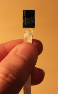 ystem consists of two back-to-back Stonyman vision chips, an Atmel ATMEGA 328P microcontroller, an oscillator (16Mhz), and a voltage regulator. The chips have flat printed optics (as described previously) with slits in order to take one-dimensional images of the environment. Even better, the Atmel has the Arduino bootloader, so the sensor is an Arduino clone and can be programmed through the Arduino IDE. The entire system weighs approximately 300-350 milligrams and has dimensions of 8x11 millimeters.