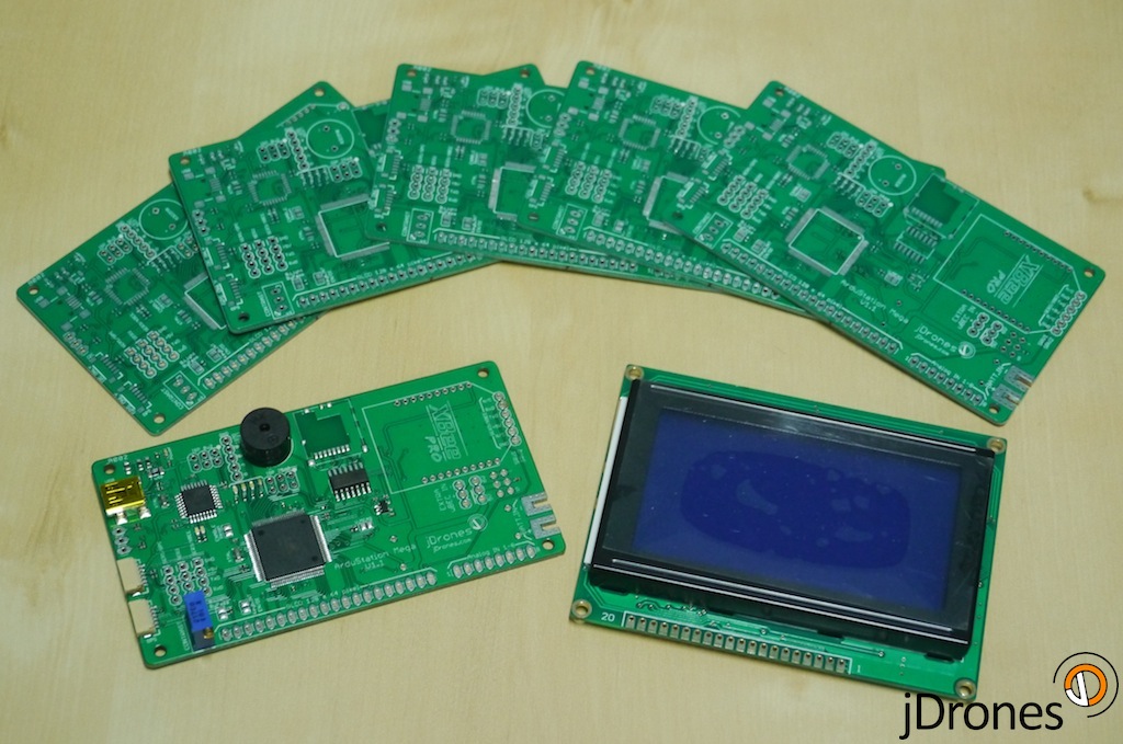
Our ArduStation MEGA boards arrived today and I am truly excited to see how they work. Now starts small assembly job for them and then we can start doing testing for those.
Big thanks for Colin for his original ASM work, it's great to see what great minds can create.
New boards looks just awesome. Few connectors are missing but those are quickly soldered. These boards are from the first batch and we have them now small qty in stock. If there are any changes that needs to be made, we will do it and then first production batch will come.
Technical specs:
- MCU: Atmel 2560 with Atmel 8u2 USB "adapter"
- XBee footprint for telemetry with external pins
- IO: Buzzer, Analog, I2C, GPS
- SDCard holder for storage needs
- 128 x 64 pixel Graphics LCD
- 3 x TTL Serial output pins
- 2 x Servo outputs with internal/external power feed
- Encoder port for menus etc use
- Connection for I2C Keyboard
- 4 x LEDs for showing different statues
Jani / jDrones
Comments
Keyboard reference schematics and layout has been added to jD Document site.
@Thomas - I'm looking for the schematic for the button board that attaches to the ASM main board that you show. Paul's shows the button board above. I'm interested in the 5 solder pads to the right of the photo on the button board and to confirm their functionality. If they bring the I2C pins out it would save me from having to make a "y" cable from the main ASM board to the button board to add some other I2C devices..
@Robert,
Here is a link to the ASM documentation: http://www.jdrones.com/wiki/#sthash.NSaDLMWH.dpbs
Here is a picture of the jdrones ASM schematic:
As near as I can tell there appears to be a jumper on the board that will connect the I2C connector int pin to the processor PE6.
Regards,
TCIII ArduRover2 Developer
Jani: Is there a schematic for the button board that Paul has pictured above? I'm trying to understand what the 5 pads Paul has marked on the diagram actually are? I'm looking to add some other I2C devices to the I2C port on the Mega 2560 chip? If the 5 pads extend the I2C, Int (PE6) and power that would be great. I've haven't got my logic probe and meter out yet to do some detective work.
Thanks.
Robert...
Paul that pinorder is only valid for extra connector in side of theynkeyboard. If you want to use main i2c connector, pin order is different as it used EM406 style cables.
Robert, refrence schematics and pin diagrams are already on jDrones site, check under Documents
@ Paul: Most helpful! I have a couple of I2C devices I want to try out.
@ Jani: Looking forward to the updates. Schematic would be helpful.
Thanks.
Robert...
@Robert McC
I don't have a schematic but this is that I got the 5 pin connector pads as:
Paul
@Saiful,
Ah, the sweet smell of success:-)
Regards,
TCIII ArduRover2 Developer
Thomas thanks, I have delete all my old APM libraries and that help me alot.
Sweet :)
-
10
-
11
-
12
-
13
-
14
of 27 Next