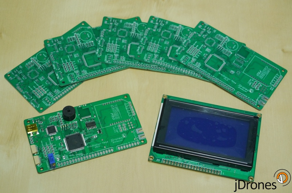
Our ArduStation MEGA boards arrived today and I am truly excited to see how they work. Now starts small assembly job for them and then we can start doing testing for those.
Big thanks for Colin for his original ASM work, it's great to see what great minds can create.
New boards looks just awesome. Few connectors are missing but those are quickly soldered. These boards are from the first batch and we have them now small qty in stock. If there are any changes that needs to be made, we will do it and then first production batch will come.
Technical specs:
- MCU: Atmel 2560 with Atmel 8u2 USB "adapter"
- XBee footprint for telemetry with external pins
- IO: Buzzer, Analog, I2C, GPS
- SDCard holder for storage needs
- 128 x 64 pixel Graphics LCD
- 3 x TTL Serial output pins
- 2 x Servo outputs with internal/external power feed
- Encoder port for menus etc use
- Connection for I2C Keyboard
- 4 x LEDs for showing different statues
Jani / jDrones

Comments
Jani thanks I will work on this today and see if I can get it up and running again. Was the servo rail powered from the USB also or only from the Batt Reg side.
Jack
Paul, yep it works already just fine. There were some old libraries that messed compile process on one of our computer.
Paul
Jack, pinout is on silkscreen. Take out that regulator and you will see. Regulator IN+ is next to BAT+ and Regulator OUT+ is on other end. GND pins are those close to display connector and BAT- connector.
Jani
if I were to install a new reg. could you show me the pin-out . tried to feed 5v to the board at the opposite end of the reg. and still now bower to the board. If I use USB the board powers up and looks good but no power to the servos.
Jack
Colin where is your A8 being set?? I trying to get my engineers on speed on coding with code and there are several compile problems. Have you included all libraries etc?
Jack yes voltage regulator on board is giving out 5 Volts like Colin said. Jumper on board defines servo input voltage, either internat 5V regulator or external source. External source will be connected on second jumper row.
All,
Had quite a long programming session this evening. Version 0.5 is ready:
Mediatek 0.5
UBLOX 0.5
I managed to get auto detection for the GPS working, but it seems a bit unstable, so for now I've compiled two versions- one for each GPS type.
Copters now have two parameter pages: A rate PID page and another page with parameters that looked reasonably useful on first inspection. I haven't really played with copters for about a year, so am having to play catchup on what functionality is going to be useful in the field. Feel free to add enhancement requests via the issue tracker.
Button board rotation may now be changed in the setting screen. Scroll down to the bottom and you have four options: up down left or right. Basically select which edge the white connector on the button board is on. Your selection will be saved to the ASM's eeprom. The default behaviour is to have the white connector on the right hand side- so maybe hold your unit sideways/upside down if that helps you navigate there!!
Other settings are available in the setting screens, but don't do anything yet :P
Vehicle parameters are downloaded automatically a second after making a connection. Progress for this can be seen on the second page- just a simple text indication at the moment.
Regards,
Colin
That sucks. I hope you can fix it!
Pretty sure it's a five volt reg. I think there's a jumper so you can decide whether to use onboard or offboard power for the servos. Apparently the regulator can supply 2 amps. On my board the jumper is in the position shown in this image (the left of the three pins, labelled external power):
http://www.jdrones.com/new/wp-content/uploads/2013/08/ASM_Motherboa...
But the documentation on what to do with the jumper is a bit vague
Hopefully Jani can fill you in with more details
anyone know what the output from the on board reg. is. I think its 5v but want to make sure didn't see it in the schematic. Was testing with two small servos to see how the antenna track works, servos were working OK for about 5 min then the servos started to vib. and the lights went out. cant power up with batt. but USB still works. I want to replace the V reg. on the board as it was hand built and was very bad soldering so I think that's the issue.
Jack
-
5
-
6
-
7
-
8
-
9
of 18 Next