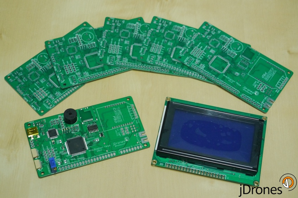
Our ArduStation MEGA boards arrived today and I am truly excited to see how they work. Now starts small assembly job for them and then we can start doing testing for those.
Big thanks for Colin for his original ASM work, it's great to see what great minds can create.
New boards looks just awesome. Few connectors are missing but those are quickly soldered. These boards are from the first batch and we have them now small qty in stock. If there are any changes that needs to be made, we will do it and then first production batch will come.
Technical specs:
- MCU: Atmel 2560 with Atmel 8u2 USB "adapter"
- XBee footprint for telemetry with external pins
- IO: Buzzer, Analog, I2C, GPS
- SDCard holder for storage needs
- 128 x 64 pixel Graphics LCD
- 3 x TTL Serial output pins
- 2 x Servo outputs with internal/external power feed
- Encoder port for menus etc use
- Connection for I2C Keyboard
- 4 x LEDs for showing different statues
Jani / jDrones

Comments
Jani, on the hardware, the keyboard buttons are a bit nasty! Addition of an encoder is really useful and might be worth building in. I'm hacking together an separate i2c button board for quick and easy mode changes (5 nice Cherry keys in a row with LEDs to indicate mode)
@Colin, great progress on code. Looks like we need to fork 0.6 again to our main antenna tracker box. Colin did you find all pins ok from board?
Would be great to get some feedback for hardware as we are planning to make new revision of it in next 2 months or so. At least new board will have internal regulator and few extra fuses. Also keyboard will get some facelift
I've just updated the wiki page on creating custom pages for ASM. It's a bit brief, but points out where code needs to be inserted. Might help if you're tinkering....
https://github.com/cgwood/ArdustationMega/wiki/Creating-a-Custom-Page
Hi All,
Version 0.6 is now available:
Mediatek
UBlox
Since 0.5 I've improved the parameter download reliability even further. The parameters download automatically, the progress is now smoothly updated on the "ASM Status" screen (page 2) and the ASM will retry if any timeouts occur.
The second page is the ASM status page. I've gathered some of the information that was scattered about into this page. It gives a good overview of the health, such as downloaded parameters, gps and SD status and what the average period of the heartbeat is (for APM, we want this to be around 1000ms, if it's a lot larger then we're dropping heartbeats). The time being displayed is taken from the GPS output; you can update this for your timezone by going to the GPS Timezone option on the settings page.
I've fixed the pin mappings for the jDrones ASM for radio RSSI and ASM voltage detect. These are indicated on the main page by the left two vertical bars. If you want to use radio RSSI you need to plug the analog RSSI out from the xbee into the leftmost analog port (next to the GLCD header) on the ASM board. I'm not sure if the 3DR radios have RSSI out... perhaps they can do it in software?
Whilst on the subject of the main page, the right hand side is the UAV voltage status. The sat count is now the sat count for the UAV, as are the altitude and speed (these were previous ASM values whilst I was debugging). The circle is an indicator for the bearing to the UAV- although I think this is playing up a bit at the moment. Underneath the circle is the distance to the UAV. The number of after Plane/Copter/Rover is the mavlink system id of the vehicle- maybe we can do something useful with this at a later date...
Copters now have a settings page on top of the rate PID page. Although these could probably do with updating based on any feedback users are able to give me on the most useful parameters and ordering / groupings.
I've revamped the button behaviour- previously I had a quick hack in place so we could hold buttons down to get repeat behaviour. Now there are two settings you can change (in the settings page), which are: delay before repeating occurs and delay between button repeats. In other words, when you press and hold a button it will wait 500ms before effectively registering another press of the button and then every 150ms after that it will press the button again. This is the case for up,down,left,right but ok and cancel you can hold down for a long press - not for repeating.
Hopefully that made sense... Either way, you can fiddle with those two keypad delay settings if you don't like how the buttons respond. Also, we now have the option for long pressing / holding the ok button on some pages to enter menus etc.
I fixed a bug we had on elevation in the antenna tracking code (thanks Jack). Also, to make development life easier, I've added a page for the antenna tracking. From here you can see what the calculated bearing and elevations to the UAV are. You can also see the servo output positions in percent. If you have a rotary encoder attached you can use this to overwrite the calculated bearing or elevation angles to test the servo operation. Press up and down on the keypad within this screen to determine what the encoder is altering.
The settings have been updated, so when you upload this version you will lose all of your settings and have to re-pick them again.
Regards,
Colin
Then diode fix seems to be working OK went over the board and didn't find anything that would have caused it other than the new xbee interface board using my old one now and still looking at the new one. When you do a release can you do a hex as I still have trouble compiling Arduino for this board for some reason. Never had any trouble with arduino before but it is a library thing I guess. I will have to work on that.
Thanks for looking at the servo issue for me.
Jack
Jack,
I found the bug. The servo was being commanded to move between 70 and 90 degrees at 50Hz, rather than following the calculated elevation.
I've fixed the bug and pushed to master, so will include that in the next release.
This has highlighted that I should probably put some protection in the code, like setting a maximum servo slew rate - like the throttle in APM:Plane. If you got a noisy GPS measurement (like on startup), your elevation could start oscillating. I don't know if this will actually happen, but belts and braces!
I take it this means your diode fix went well?
Regards,
Colin
The survo output is the on away from the board edge I think it is the elevation ?
Thanks Jack
Sure, I'll take a look. Which servo port is it that is going wrong for you?
I've only really been playing around with the bearing servo so far... Elevation is in there, but I've barely touched it.
Colin
Wander if you could make a quick check as I am trying to check Antenna track but when I plug in survos one seams to respond correctly and the other just pulses bad and gets hot. This is the issue I had when by board went out so I thought it was something with my board but when I loaded hex 3 the survos seam to work OK. reloaded hex 5 ublox and survos go crazy. Pretty sure its a software issue maybe your software and Janis hardware are different ? If you could plug in some survos and check the outputs it would help me debug this.
Jack
Hopefully tomorrow evening. I'm not about tonight. Should be a good update, I got a lot of niggles worked out over the weekend :)
-
3
-
4
-
5
-
6
-
7
of 18 Next