The flying wing design I have been working on for some time now has been slowly evolving as I have learned more about aerodynamics and expanded my skill set with modelling tools of various forms. I have recently completely re-surfaced my design with new aerofoil sections and better, more consistent surface transitions and have been experimentally analysing the results with CFD, courtesy of OpenFOAM. I want to present some of the results here to share.
The lead image is the latest design iteration analysed in OpenFOAM at close to stall angle of attack and the following are a couple of renders of the latest surfacing.
Along with developing methods, I have learned a few things about what makes flying wings tick and how they can be better optimized, at least in the genre that I am pursuing. Some interesting, I hope, insights follow:
Aerofoil selection appears to be the one thing many obsess over when designing a flying wing, but I have found it is only a very small part of the equation and gains made here in two dimensions can be easily lost in the transition to 3D. Many flying wings appear to fly with a large amount of elevon-induced reflex, demonstrating that aerofoil selection alone is inadequate. In a sense, it is equivalent to a large decalage angle to compensate for a low tail volume which is a pretty inefficient way of achieving the design objectives.
I have several iterations of aerofoil in this design, a root foil whose origin is now unclear and a tip foil which started as a symmetrical NACA foil, but wound up with a little camber in the end. Much of the initial development was done in XFLR5 but the CFD proved illuminating in areas not possible with panel code alone.
Washout has proven to be a much more powerful tool to add pitch stability and, in both geometric and aerodynamic senses, has surprised me in how much is actually required to do the job. I have about 7° geometric in this design and in addition have an inverted aerofoil section (a NACA 1308)) for the wingtip to add a relatively large amount of additional aerodynamic washout. Despite this, the undeflected trim speed of this design is of the order of 24-25m/s At this Reynolds number scale, washout has an advantage over reflex that hopefully will become clear shortly. The next image shows the airframe at about 24.5m/s and demonstrates pretty clearly the lift distribution through the downwash trajectory.
One of the big hurdles of flying wings is to maximize the CLmax value which determines the maximum wing loading and landing speeds. Despite the large washout, the stall consistently begins around the tip which is where much of my attention has been focused.
Early on in my investigations I discovered that wing sweep can have deleterious effects on stall performance. In hindsight, I was rediscovering what the Russians already knew from their MiG15 design onwards and attempted to alleviate with those huge wing fences. The effect of wing sweep at stall is a reverse spanwise flow on the upper wing surface. In part this is caused by a changing spanwise pressure gradient as the AoA increases where the inboard high pressure zone is interacting with the lower pressure zones further outboard. The boundary layer flow model below helps visualize this flow regime quite dramatically, although at this Re scale, I predict that it tends to form a laminar separation bubble/vortex running span-wise along the wing surface.
 (MiG-17 showing clearly the wing fences for controlling reverse span-wise flow at high alpha)
As demonstrated in the above illustration, the design optimization of the elevons is an area that is ripe for further DIY exploration. I have found that traditional full-span elevons are counter productive because as the elevon reflex is added, the aerofoil section CLmax is reduced. I have instead experimented with various size and proportion elevons at the wing tips, leaving the inboard wing section unmodified with control surface deflection. This elevon design appears to do the job of increasing the aerodynamic washout of the wing as much as adding reflex, both effects working in parallel to reduce its trim speed accordingly. Unfortunately the foil section modified by the deployment of the elevons tends to be negatively affected giving rise to a large adverse pressure gradient early in the chord causing flow separation bubble formation and loss of lift - the bubble in effect causing a dramatic thickening of the effective aerofoil section with a near total loss of reflex. For this reason, I think washout provides some interesting advantages over reflex at this scale.
To alleviate this separation bubble phenomenon, I have experimented with the use of "spoilerons" - in effect a kind of inverted split-flap design. The top surface of the foil section is deflected upwards leaving the bottom surface unmodified. By opening a gap at the leading edge of the spoiler surface as it is deployed, the negative pressure behind the spoileron tends to improve the pressure gradient along the foil boundary layer helping to delay the inevitable separation somewhat. The spoilerons have also appeared to be extremely effective at quite small sizes relative to conventional flap-type elevons and have led to a minimal impact on drag at low angles of attack.
Spoilerons have not entirely solved the problem of wingtip flow separation so I have added leading edge slots in this latest design iteration. I would not consider them yet optimal, but they tend to add about 4-5% to the CLmax as they stand. They also may have had a non-trivial impact on CD0, but I haven't yet enough data to demonstrate or quantify this.
The results so far predict a best L/D just shy of 12:1 at around 16-17m/s with a span of 975mm and a 1.2kg AUW. There is a small non-linear effect with weight variation due to Reynolds number effects at this scale, some of which can also be seen in the measured drag polar data, where drag at high AoA increases much more sharply than predicted by conventional drag coefficients. This is almost certainly a result of separation bubbles forming - at least theoretically. I don't wish to imply that the CFD data is infallible.
Despite the use of CFD, I haven't yet managed to achieve my theoretical design goal of 10m/s stall speed at the design weight (1.2kg). It currently sits somewhere in the region of 11m/s for a CLmax of 0.65-ish. Note that the reference area is close but still a little unclear at this point due to the "flowing" wing planform so the lift coefficient data probably isn't directly comparable.

I am doing further analysis based on these aerodynamic characteristics to establish propeller selection, range, payload, climb performance, battery size etc, however initial estimates are very encouraging, putting range at or exceeding 100km on 8 x NCR18650B's. With careful airframe design, this allows for at least a 250g payload as well as both video (5.8GHz) and telemetry (915MHz) data links aboard.
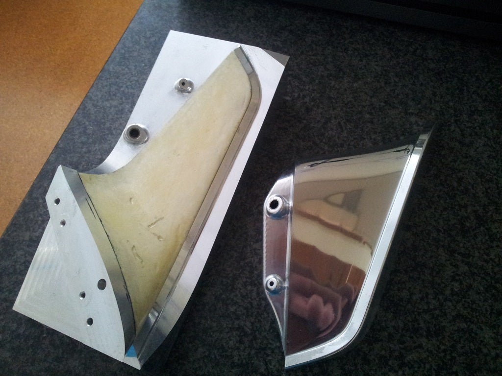
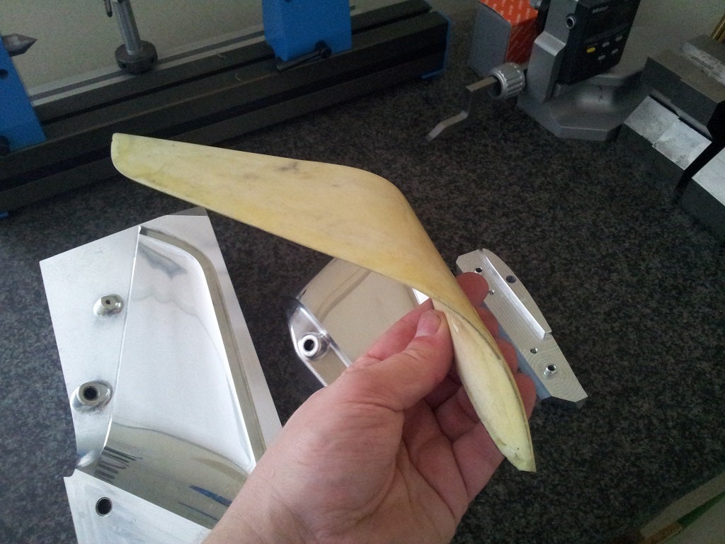
I envisage a fully moulded composite airframe to meet the weight targets, make it robust and to yield a good surface finish for drag minimization. Along side this work, I have been experimenting with some construction techniques on a winglet sample. The results of this experimentation will help drive some of the design and strutural analysis. The potential for high quality surfaces is definitely there but will take some process development and an amount of overly sticky fingers to achieve.
There are a bunch of detail design issues yet to resolve, not least being the manufacturing methods for a robust spoileron at an affordable cost. The non-trivial issue of downward control surface deflection has also to be addressed in mechanical and aerodynamic terms.
Unfortunately as this is all self-funded to date, so progress will continue apace, where the pace will be more tortoise than hare. I hope to publish further info about how I've gone about range analysis, propeller selection as well as some more details about how I've used CFD.
Thanks for reading if you've got this far. I hope it's been interesting
Comments
@Martin, my design has been focused on maximizing CLmax. If you need elevon deflection at high CL you run into the reverse spanwise flow problems I describe in my blog post. This is the reason that a) I don't want full span elevons, b) I don't want huge elevon deflections to start with and c) that I was experimenting with spoilerons.
Flying wings have really poor CLmax so contrary to tailed designs, stall/landing performance is one of the things that drives the whole show, unless this matters not at all for what you need to achieve. Ultimately, wing loading and zero-lift drag are interrelated through min speed requirements.
Green is Cm at neutral point with your wing with no elevon deflection. Blue is at 5% SM no deflection.
Red is same wing, same data at 3.64° elevon deflection.
Yellow is high-washout design with no elevon deflection.
@Andrew
Explane me please blue and green lines on Cm/Alpha graphs
@Andrew,
It seemed that the tip chord was smaller, 150 mm should be ok.
Large amount of twist is ok for a plane that 90% of the flight cruises at a specific speed.
Elliptical lift distribution is only optimum for a fixed span planar wings and fixed weight. There is no overall optimum. Increasing AR will always increase performance. With winglets the fixed span optimum lift dist isn't elliptic.
From what I've learned is that if you want good performance for a wide speed range one should optimize for low CL. That means no elevator deflection at max design speed. A little elevon delfection at high CL won't hurt the performance much because parasitic drag is smaller at low speeds.
By "jumping" the chord in the elevon area it's also possible to lessen the effect of the elevon deflection on the lift distribution.
http://wiki.rc-network.de/index.php/Auftriebsverteilung-Goldene_Regel
http://www.multibumm.de/
@Martin,
Wingtip chord on main plane was about 150mm. On the winglet it is obviously much shorter but this is really only there for yaw stability and an aerodynamic place to store telemetry antennae.
I think it's also worth remembering that good stability/high static margin will give you lower power consumption for the control system. Stability from continuous servo motion costs you precious battery capacity. This wing isn't designed or intended to be a sporty combat wing but rather a stable, long-range platform for aerial photography of various forms. High speed isn't necessarily a requirement either but tip elevons can mitigate the effects of washout quite easily allowing high speeds with little compromise.
And regarding constant CL or elliptical lift distributions, I'd argue this isn't always an optimum solution in a practical world.
As you say, sometimes you need to make compromises and, if you don't keep in mind the assumptions you are making to get there, some solutions seem odd and can be too easily dismissed.
Addendum: All the data calculated for the above post is using 5% MAC static margin
OK - quick and dirty XFLR5 experiment in response to Vladimir's claims. A crude design based on the design parameters presented above.
Firstly, as it stands, Vladimir's wing will not fly without elevon deflection. Best L/D deflection for full-span elevons comes out at -3.64° for 20% chord control surfaces.
By increasing the tip washout to 5.7° (profiled from 1.5° at 75% span) and changing the tip foil to an inverted NACA 1410, the same best L/D speed is achieved without any control deflections and L/D improves by a smidgin. (27.09 to 27.36)
Now this isn't conclusive by any stretch and one can tear this analysis apart for many reasons, but the key point is that judicious use of "extreme" washout can be used to better optimize swept flying wings compared with the "safe" numbers people are expecting.
I would also add that over-reliance on elevon deflection for stability backs you into a corner when it comes to minimizing stall speed for the reasons outlined in my original blog post.
@Andrew, Very nice work. I know how much time goes into quality simulations like this. And I agree with your points about airfoil selection, sweep, and washout. Those are things not generally understood, and it's great to see someone taking the time to carefully examine them.
Keep up the good work, and I'll look forward to seeing your progress!
@Andrew, I'm glad we're on the same page.
The CL distribution from XFLR5 is good enough.
The needed elevon deflection/washout/reflex has mostly to do with the static margin. If you want a high static margin (for manual control) you will have to sacrifice performance one way or the other.
Those taper ratios are pretty high. What's your tip chord?
Vladimir has got it - you can easily achieve on or the other (constant CL distribution or elliptic lift distribution), but not both at the same time. Some compromises have to be made.
Thanks Vladimir. I will analyse that tomorrow and post the results.
-
1
-
2
-
3
-
4
-
5
of 5 Next