jDrones News: jD-IOBoard v1.0 update
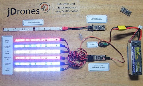
You had some problems on driving LED strips or something else?? Well no problems anymore.... We have seen people making all type of darlington/transistor and similar hacks to drive their LEDs, Sirens and so on but they all need a lot of hacking and they might not be suitable for long term solution.
We answered on this call and made fully Arduino compatible called jD-IOBoard that can run Single LEDs, LED Strips, Loudspeakers, Buzzers, Power switches and so on. It's upto your own imagination on what all you can control with this board.
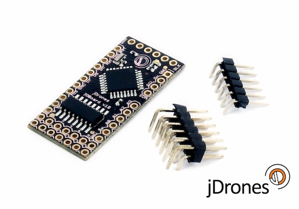
So what does this board actually do?? It has fully Arduino compatible ATMEGA 328 MCU and Darlington array to driver high power outputs. Also I2C pins are exposed and same as many TTL level IO and Analog pins. As you can see from picture above.
Board has:
- 6 x High power outputs, max. 500mAh / 50 Volts
- 4 x Analog inputs (6 if you don't use I2C port)
- I2C port for controlling, listening I2C messages
- 6 x TTL level GPIO pins (8 if you don't use FTDI)
- 1 x FTDI port
3 high power outputs can also be controlled by PWM output while another 3 are just normal "On/Off" outputs
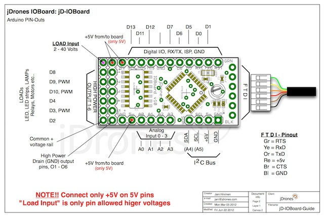
How those Arduino pinouts looks like:
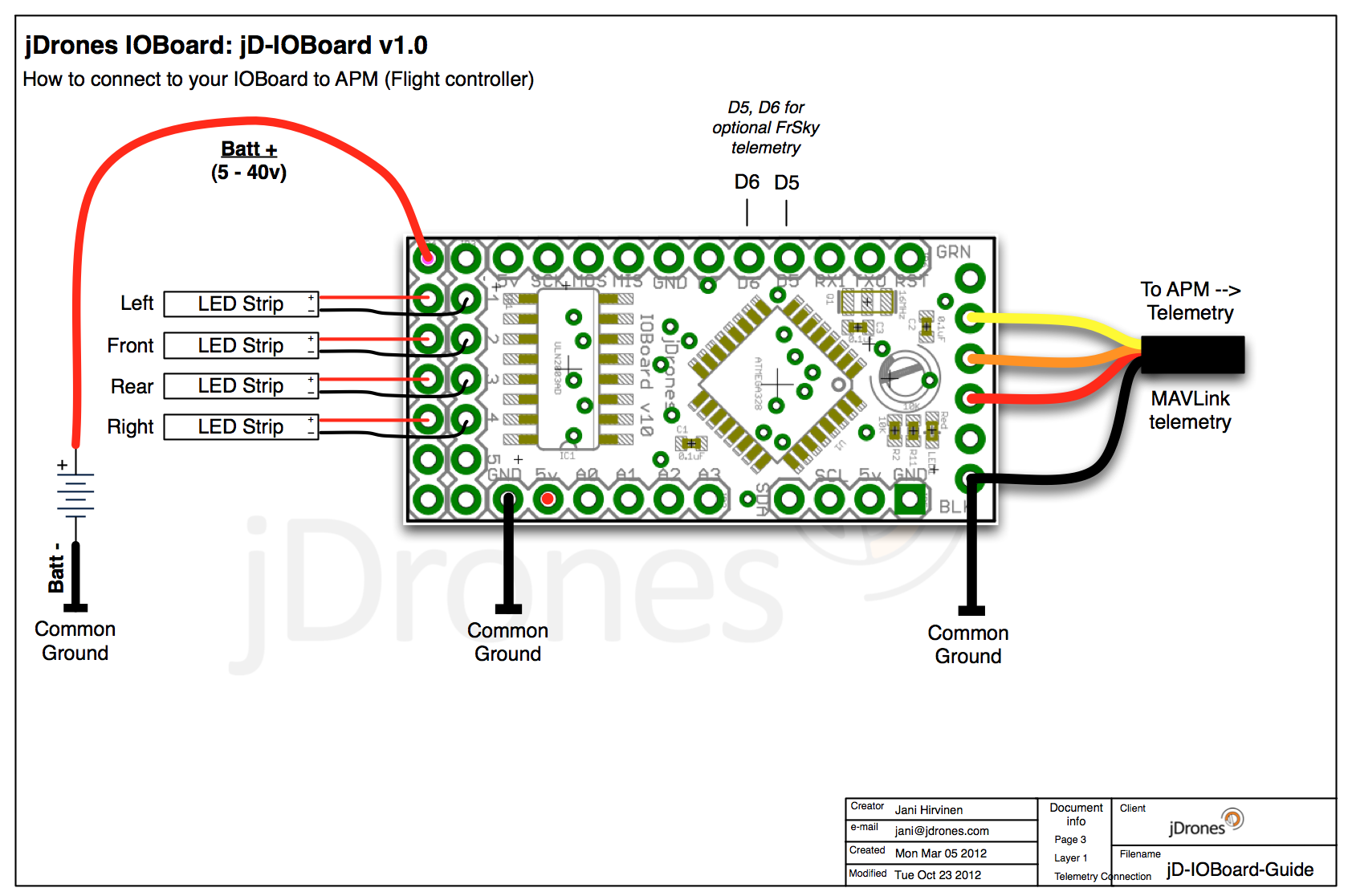
Connecting LED's,Buzzers etc is really simple. Just use one of output pins on end of the board. Below you can see examples on how to connect LEDs or LED Strips on it.
Pictures does not give enough credit for how it works so we made small video to show just few examples on how to use it. There are many other ways to do it but this should give at least some idea what/how to run it. So have fun watching it.
Get yours from jDrones Store: jD-IOBoard and have a blink blink.
Ps. There are some nice features coming to this board shortly...
Comments
@LTMNO, thanks to @Jani - that is exactly what I did.
To make it simple I just take V(in) from balance port of main battery.
@LTMNO, i think Arseni means A2 pin on FrSky receiver. Yes that is one way but you need to be careful not to burn your FrSky receiver. It's A1 and A2 pin inputs can only handle 3.3 volts so you need to have voltage divider that matches this output voltage.
To do that you need to have this type voltage divider and if we want to scale max 0-14volts to be 0-3volts we can use for example R1 = 10kOhms, R2=2.72kOhm resistors
@Stefan great :)
@Arseni, curious to what you were saying about splitting the wire... from the APM Power Module and the 6 wires that come into the APM... is there a schematic on which one of those wires carry the voltage for the Batt Signal. As in, are you speaking about one of these wires to take to the A2 of the Reciever?
I received my replacement board last week but didn't have time to check it until today. The replacement board works without problems. Thanks!
As a temporary workaround, voltage can be read by receiver itself (A2), just need to split voltage wire and link it to receiver. So we have temporary workaround :)
This is really great project. Thank you!!!
Yes there are still issues with battery voltage calculation and few other minor bugs that we are trying to solve. FrSky protocol is rather limited/restricted so we need to find optimal ways to play with it.
Just tried the new MAVLink/FrSky v0.3a with FrSky
Everything is working good, Great job guys!
The only Issue I have is voltage reading (See the video):
https://www.youtube.com/watch?v=9FjP4nZmg2M&feature=youtu.be
on FrSky FLD-02 cell count jumps to 1s time to time (but remains fine most of the time)
But 9XR (open9x), gets confused and shows readings completely off.
------------------------------------------
MAVLink/FrSky v0.3a
FrSky Receiver: D4R-II
Wiring:
Arduino D5---D4RII RX
Arduino D6---D4RII TX
Arduino FTDI --- APM Telemetry port (Both TX & RX are connected)
APM version: 2.73
Hi Jani, Sorry. Makes sense now. :)
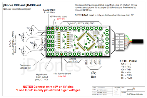
Andie i meat 3rd diagram on top of this post.
This one:
Note! Now you can add additional GND from your "light" battery next to Battery+ input pin. If you are not sure. Take alook at Difference between V1.0 and V1.1 picture and you see that there is new GND on top of output pins.
No 3rd diagram. :(
-
2
-
3
-
4
-
5
-
6
of 24 Next