Hi Everyone,
I'm currently using Madgwick's popular filter for my own AHRS project. After some experimentation with sensors and adjusting the beta gain, I've noticed some unpredictable behavior of the filter. For example, euler angles computed from the quaternion changed unexpectedly to 20 degrees off the reference angle (in a static scenario!).
After setting the magnetometer input to (0,0,0) the problem stayed the same. Then I removed the gyroscope inputs (0,0,0) and the problem stayed the same. My conclusion was that it must have been related to the accelerometer inputs.
After experimenting with real sensors I moved to artificial ACC input data and set up a test bed for Madgwick's algorithm (MadgwickTests on GitHub). I've figured out that in Madgwick's algorithm the fast inverse square root leads to huge instabilities when noisy measurements are applied. As an example, consider the pitch and roll angles shown in the following image:
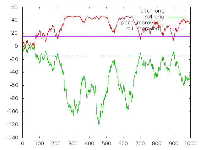 The input for the filter was: gyro = (0,0,0), acc = (2.5, 2.5, 9.15) +- 0.1 uniform noise (see test.c for details). As you can see, the pitch and roll angles (red/green, in degrees) of the original implementation show unacceptable variations.
Remarkably more stable and accurate pitch/roll angles (blue/magenta) were achieved by exchanging the inverse square root implementation. I used the following code from Accurate and Fast InvSqrt for computing the inverse square root of float x:
unsigned int i = 0x5F1F1412 - (*(unsigned int*)&x >> 1);
float tmp = *(float*)&i;
float y = tmp * (1.69000231f - 0.714158168f * x * tmp * tmp);
Cheers, Tobias
Replies
https://github.com/ptrbrtz/razor-9dof-ahrs/blob/master/Arduino/Razo...
According to this, try the Madgwick filter using this sensor input order:
-gx, -gy, -gz, ay, ax, az, mx, -my, -mz
Do you mean sensor outputs without swapping axis? It looks like
-gx, -gy, -gz, ay, ax, az, mx, -my, -mz
works. However, your quatToEuler() breaks when I use it with IMUUpdate(-gx,-gy,-gz,ax,ay,az).
Pitch and Roll won't go over 45deg.....
I am so confused now but I will give this a try. https://github.com/TobiasSimon/MadgwickTests
Basically I am just gonna use the same update() and quatToEuler().
May I ask what do you feed into update()?
Also, gyro and acc on my 9dof IMU are aligned in all three axis, so according to right-hand rule, the gyro should give correct data. Why does Madgwick's algorithm need inverted values? I tested with positive values and it integrates to an angle(theta) but converges to -theta when not moving. It's definitely integrating in the wrong direction....weird....
You are right, gyro and acc are correctly aligned. Maybe it's a good starting point to look only into the IMU update function first.
In our case, gyro and acc are also correctly aligned (mpu6050). We feed the following in the update function: gx, gy, gz, ax, ay, az (nothing is swapped or inverted). Could you please check the behavior in this case?
I found out why now. There are multiple QuaternionToEuler() function out there with different conventions. The one I used happen to be using different coordinate system.
When I aligned all three sensors using right hand coordinate system, it works directly with all the sensor input. It's weird because I tried the quaternionToEuler() function in Madgwick's paper it didn't work at all. The output angles are just unstable and sometimes rubbish.
Anyway it works perfectly now. Are you by any chance tuning the filter in real-time? Like changing Beta when there are linear acceleration is very big? I am working on an adaptive tuning scheme and trying to reduce down the dynamic error to +-0.2 deg. What I have now is around +-0.5 deg when +-0.3g is applied perpendicular to the direction of gravity.
Hi Tim,
I am so confused about the coordinate system apply in Madgiwck filter. What is the output world coordinate system of the filter? Is it ENU (X point to East, Y points to North and Z points up). What should I feed into AHRSupdate() function if I apply Madgwick filter in Android mobile which has coordinate system as picture.
I am appreciate if you can make me clear this point. Looking forward to your reply.
Hi Tobias,
I have been using this algorithm for quiet a while now, but I found some problems with it
when using the MARG algorithm instead off the IMU version it seems very slow and having some overshoot.
In the picture below you can see the X as turning using MARG and IMU. The real motion is the same.
Did you had any problems with that ?
I made some measurements
Beta =0.05
Red= IMU (Gyro+Acc), Blue= MARG(Gyro+Acc+Mag)
And some steadystate measurements
Red= IMU (Gyro+Acc), Blue= MARG(Gyro+Acc+Mag)
Every sensor upside up (pointing to the sky)
Red= IMU (Gyro+Acc), Blue= MARG(Gyro+Acc+Mag)
Every sensor upside down (pointing to earth)
Especially the last one is strange, on the Y-axis the IMU goes negative and the MARG positive.
And with the yaw the same and it is has al large overshoot and take almost 50 seconds to stabilize. The slow startup is for both orientations. The quad is in the last two pictures completely static.
Graph were made with Sebastians his Matlab scripts.
Did you had the same overshoot ?
Hi Jeroen,
right after filter initialization, we can observe a similar behavior of the filter.
I guess that the different convergence paths in your last figure depends on the gradient descent algorithm itself. However, this shouldn't be a problem.
We use a decreasing beta gain in order to have quick convergence in the beginning.
This is the slow version with fixed beta gain; convergence approximately at step 6000:
This is the fast version with decreasing beta gain; convergence approximately at step 300:
In practice I do the same, start with a gain of 2 and then decrease to 0.05 in 10 seconds.
I did noticed something else yesterday, I captured some sensor data 10 min long and put them in the matlab script, everything was stable. But in practice the yaw needs more 10 minutes to stabilize when the sensors are upside down.
I don't see this in matlab, so there most be something wrong in my C-code.
Is there a possibility that you can test with your quad the yaw at startup when upside down (top of sensors pointing down) ?
In contrast to you, we have a quite big beta in the beginning. The behavior of the Euler angles when it is oriented upside down is shown here:
-
1
-
2
-
3
-
4
-
5
of 6 Next