Andrew Rabbitt's Posts (16)

Sort by

3689700590?profile=original

A climb-glide routine can potentially yield a useful increase in range compared with the same airframe/propeller/motor combination operating straight-and-level at best range speed point or best endurance point respectively.

Let me explain briefly with graphs of the results how I have come to that conclusion, at least theoretically so far, hopefully including some useful detail on the method of my calculations and models.  I intend to experimentally validate this concept at some point with my APM-powered Skyfun, so I have tailored this example with measured and guestimate data as best I can for this style and size of UAV.  The propeller is oversized compared with what is normally run on the Skyfun (8" vs 5-6") due to the non availability of data at the smaller sizes.

Best Endurance Steady-state Flight

Firstly, we look at the airframe drag power curves as a function of airspeed. For this model a simple Prandtl model of an aircraft is used. The form drag power and induced drag power combine to form a "U"-shaped total drag power curve with a minima representing the best endurance point (lowest power consumption). The point where a tangent line to this drag power curve passing through the origin touches the curve, (or, in the case of head or tailwind components, with the origin point offset in the speed axis by the appropriate offset) yields the minimum energy consumption per unit distance - i.e. best range speed. This is all valid for steady-state, straight-and-level operation and is only considering aerodynamic power absorbed.

70939574?profile=RESIZE_1024x1024Adding in the propeller and electric motor models to the calculation, we can estimate the shaft power and electrical power consumed to overcome this aerodynamic drag.  The propeller model is a regressed 4th order polynomial surface model based on UIUC propeller data The efficiency curve for an 8x6" APC-E propeller shown here shows how the polynomial model compares with the UUIC data.  This model is actually two models -  one for thrust coefficient and one for power coefficient.  It isn't a perfect model by any stretch, but it allows an analytical solution for the overall modelling process.

3689700531?profile=original

The electric motor is modelled as a first-order model as described by Mark Drela

The motor Kv was estimated to give a voltage requirement for a 25% climb gradient at 28.5m/s of approximately 14.8V (4S battery pack assumption). This is somewhat arbitrary and the assumption does influence the motor efficiency somewhat, but it also gives a realistically useful top speed estimate of 33-34m/s. It is possible to optimise the motor efficiency in cruise a fraction further by manipulating the Kv value, but only by choosing to compromise climb and max speed performance. The motor model used yields a peak efficiency of a realistic 81%

3689700605?profile=originalHaving modeled the propeller and the motor, these two power curves sit respectively above the aero drag curve by an amount representing the successive inefficiency of each of these processes.  The minima of the electric power curve now yields the best electrical endurance speed and, likewise, the tangent point for best electrical range speed. Note that both points are at somewhat increased airspeeds - something to bear in mind even for straight and level operations!

3689700544?profile=originalJust for interest, here below are the propeller and motor efficiency curves for steady-state flight.  It shows clearly some of the compromises of steady-state operation where the efficiency points of the electric motor and propeller are obviously not co-located. Notice too that increasing speed increases the total propulsion efficiency, excepting that the gain here is subsequently lost in airframe drag.

3689700661?profile=original

System Efficiency during Climb

If we now add a climb (vertical) velocity, then knowing the airframe mass (in this example specified at 1kg), we can quite easily calculate the additional power required to climb and add this to the net thrust power. Not forgetting to correct for the increased hypotenuse speed of the climb gradient, this generates a new thrust value the propeller needs to generate, hence a higher propeller speed, more shaft power and therefore more electrical power. This is shown in the following graph, where the best range climb point (curve minima) is clearly visible. A key point to understand is that much of the extra power expended is being stored in a potential energy "battery". (PEB). There are some subtleties here that I have not modeled, since increasing climb angle transfers some of the airframe lift duties to the propeller thrust. I initially attempted to do the vector math, but quickly threw it in the too-hard-for-now basket, however I may revisit this. I do suspect the effects are small and potentially favourable.

3689700708?profile=originalNote how the best range speed during climb is faster than at straight-and-level.  This is useful because it compensates for the climb angle reducing the horizontal speed and also helps offset the slower best L/D speed during the glide period.  In this example, as we will see in the calculations below, the net horizontal speed (but not necessarily ground speed) is within a bull's roar of the best range speed when straight and level.

3689700626?profile=original

Glide Performance

For this modelling exercise, I have assumed, reasonably enough, that the glide mode will be at best glide ratio, which in this case is about 8.5:1. The second graph above shows the peak L/D to be coincident with the best range speed from the airframe drag power curve - no voodoo in that, really.

It's worth noting that optimal glide performance will only be achieved with a stopped propeller (or, ideally a folded propeller!). With a fixed propeller this will probably require the continuous use of the ESC brake function which may consume some power. Such are the differences between theory and practice.

Combining Climb and Glide Modes

For the horizontal speed calculations, we need to correct the airspeed to consider only the horizontal component to make valid comparisons with straight-and-level flight. Using the example of this study, this takes the best range climb speed of 18m/s at 15% gradient down to 17.46m/s horizontal speed and for the 8.5:1 glide, 15m/s to 14.89m/s. To compare directly with straight-and-level operation, if we take a climb-glide cycle, the average speed is 15.7m/s - fractionally slower than the 16m/s straight-and-level cruise. The electrical energy consumption is assumed to only occur during the climb phase, so factoring this over the whole climb-glide cycle (working in energy units/unit distance or J/m) gives an average energy consumption of 2.18J/km compared with 2.50J/km when travelling straight-and-level - a 12.7% decrease in energy consumption or a 14.6% increase in range.

This isn't actually the optimal case as calculated by this model. The 25% climb gradient yields a slightly better 15.2% increase in range, but since this model doesn't include the battery discharge efficiency, we can't be sure this really is optimal.

Note that it is now possible to trade this range gain off in the glide phase to recover or even increase the average speed over the straight-and-level condition. The choice is yours!

Where do the Efficiency Gains come from?

If we plot efficiency curves for propeller and motor together it becomes immediately clear that the vast majority of the efficiency gain is found in operating the electric motor closer to its peak efficiency. It must be emphasised that this is for this case only! Other airframe, motor and propeller combinations will move this around.

Indeed it opens the possibility of re-sizing the motor in lieu of climb-glide operation, however this will most likely limit the maximum power output of the motor, limiting climb rate and making take-off difficult without applying additional measures.

3689700713?profile=original

Summary

This was prepared for my own curiosity, but I hope that it can shed some light on the possibilities that relatively simple modelling can offer in helping to optimize a fixed-wing UAV. All this was done using MS Excel, including the regression analysis of the propeller model.

I am in no way claiming that climb-glide is the best solution for everyone's application. Merely that it is a way to improve the energy efficiency of the relatively simple hardware set that most people adopt for their UAV's.
Read more…

3689660615?profile=original

The flying wing design I have been working on for some time now has been slowly evolving as I have learned more about aerodynamics and expanded my skill set with modelling tools of various forms.  I have recently completely re-surfaced my design with new aerofoil sections and better, more consistent surface transitions and have been experimentally analysing the results with CFD, courtesy of OpenFOAM.  I want to present some of the results here to share.

The lead image is the latest design iteration analysed in OpenFOAM at close to stall angle of attack and the following are a couple of renders of the latest surfacing.

3689660736?profile=original

3689660756?profile=original

Along with developing methods, I have learned a few things about what makes flying wings tick and how they can be better optimized, at least in the genre that I am pursuing.  Some interesting, I hope, insights follow:

Aerofoil selection appears to be the one thing many obsess over when designing a flying wing, but I have found it is only a very small part of the equation and gains made here in two dimensions can be easily lost in the transition to 3D.  Many flying wings appear to fly with a large amount of elevon-induced reflex, demonstrating that aerofoil selection alone is inadequate.  In a sense, it is equivalent to a large decalage angle to compensate for a low tail volume which is a pretty inefficient way of achieving the design objectives.

I have several iterations of aerofoil in this design, a root foil whose origin is now unclear and a tip foil which started as a symmetrical NACA foil, but wound up with a little camber in the end.  Much of the initial development was done in XFLR5 but the CFD proved illuminating in areas not possible with panel code alone.

Washout has proven to be a much more powerful tool to add pitch stability and, in both geometric and aerodynamic senses, has surprised me in how much is actually required to do the job.  I have about 7° geometric in this design and in addition have an inverted aerofoil section (a NACA 1308)) for the wingtip to add a relatively large amount of additional aerodynamic washout.  Despite this, the undeflected trim speed of this design is of the order of 24-25m/s  At this Reynolds number scale, washout has an advantage over reflex that hopefully will become clear shortly.  The next image shows the airframe at about 24.5m/s and demonstrates pretty clearly the lift distribution through the downwash trajectory.

3689660808?profile=original

One of the big hurdles of flying wings is to maximize the CLmax value which determines the maximum wing loading and landing speeds.  Despite the large washout, the stall consistently begins around the tip which is where much of my attention has been focused.

Early on in my investigations I discovered that wing sweep can have deleterious effects on stall performance.  In hindsight, I was rediscovering what the Russians already knew from their MiG15 design onwards and attempted to alleviate with those huge wing fences.  The effect of wing sweep at stall is a reverse spanwise flow on the upper wing surface.  In part this is caused by a changing spanwise pressure gradient as the AoA increases where the inboard high pressure zone is interacting with the lower pressure zones further outboard.  The boundary layer flow model below helps visualize this flow regime quite dramatically, although at this Re scale, I predict that it tends to form a laminar separation bubble/vortex running span-wise along the wing surface.

MiG-17F_Top_View.JPG?width=750(MiG-17 showing clearly the wing fences for controlling reverse span-wise flow at high alpha)

3689660778?profile=original

As demonstrated in the above illustration, the design optimization of the elevons is an area that is ripe for further DIY exploration.  I have found that traditional full-span elevons are counter productive because as the elevon reflex is added, the aerofoil section CLmax is reduced.  I have instead experimented with various size and proportion elevons at the wing tips, leaving the inboard wing section unmodified with control surface deflection.  This elevon design appears to do the job of increasing the aerodynamic washout of the wing as much as adding reflex, both effects working in parallel to reduce its trim speed accordingly.  Unfortunately the foil section modified by the deployment of the elevons tends to be negatively affected giving rise to a large adverse pressure gradient early in the chord causing flow separation bubble formation and loss of lift - the bubble in effect causing a dramatic thickening of the effective aerofoil section with a near total loss of reflex.  For this reason, I think washout provides some interesting advantages over reflex at this scale.

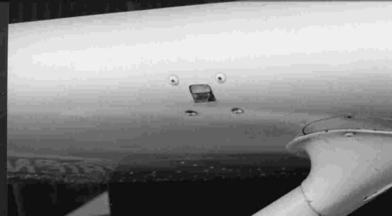
To alleviate this separation bubble phenomenon, I have experimented with the use of  "spoilerons" - in effect a kind of inverted split-flap design.  The top surface of the foil section is deflected upwards leaving the bottom surface unmodified.  By opening a gap at the leading edge of the spoiler surface as it is deployed, the negative pressure behind the spoileron tends to improve the pressure gradient along the foil boundary layer helping to delay the inevitable separation somewhat.  The spoilerons have also appeared to be extremely effective at quite small sizes relative to conventional flap-type elevons and have led to a minimal impact on drag at low angles of attack.

Spoilerons have not entirely solved the problem of wingtip flow separation so I have added leading edge slots in this latest design iteration.  I would not consider them yet optimal, but they tend to add about 4-5% to the CLmax as they stand.  They also may have had a non-trivial impact on CD0, but I haven't yet enough data to demonstrate or quantify this.

3689660628?profile=original

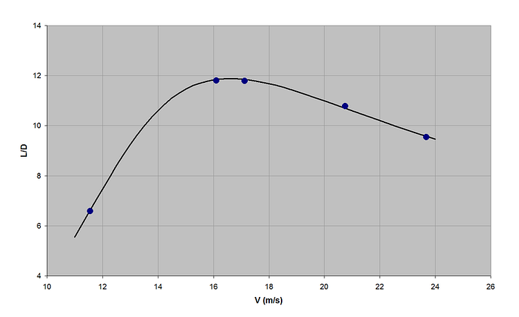
The results so far predict a best L/D just shy of 12:1 at around 16-17m/s with a span of 975mm and a 1.2kg AUW.  There is a small non-linear effect with weight variation due to Reynolds number effects at this scale, some of which can also be seen in the measured drag polar data, where drag at high AoA increases much more sharply than predicted by conventional drag coefficients.  This is almost certainly a result of separation bubbles forming - at least theoretically.  I don't wish to imply that the CFD data is infallible.

Despite the use of CFD, I haven't yet managed to achieve my theoretical design goal of 10m/s stall speed at the design weight (1.2kg).  It currently sits somewhere in the region of 11m/s for a CLmax of 0.65-ish.  Note that the reference area is close but still a little unclear at this point due to the "flowing" wing planform so the lift coefficient data probably isn't directly comparable.

3689660791?profile=original

V-LD%20Graph_zpsyklpwjrb.png?width=750

I am doing further analysis based on these aerodynamic characteristics to establish propeller selection, range, payload, climb performance, battery size etc, however initial estimates are very encouraging, putting range at or exceeding 100km on 8 x NCR18650B's.  With careful airframe design, this allows for at least a 250g payload as well as both video (5.8GHz) and telemetry (915MHz) data links aboard.

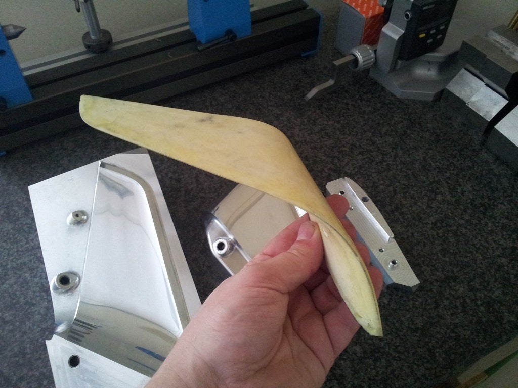
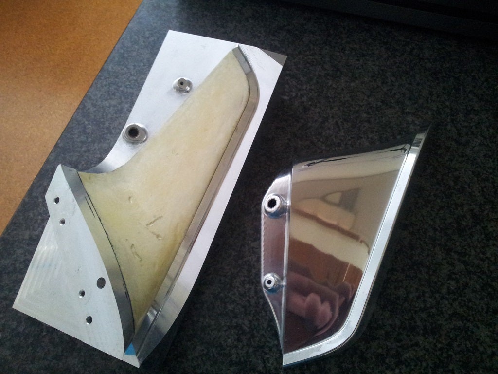
I envisage a fully moulded composite airframe to meet the weight targets, make it robust and to yield a good surface finish for drag minimization.  Along side this work, I have been experimenting with some construction techniques on a winglet sample.  The results of this experimentation will help drive some of the design and strutural analysis.  The potential for high quality surfaces is definitely there but will take some process development and an amount of overly sticky fingers to achieve.

a7566849-235-20150213_133633_1024.jpg?width=750

a7566847-42-20150213_133532_1024.jpg?width=750

There are a bunch of detail design issues yet to resolve, not least being the manufacturing methods for a robust spoileron at an affordable cost.  The non-trivial issue of downward control surface deflection has also to be addressed in mechanical and aerodynamic terms.

Unfortunately as this is all self-funded to date, so progress will continue apace, where the pace will be more tortoise than hare.  I hope to publish further info about how I've gone about range analysis, propeller selection as well as some more details about how I've used CFD.

Thanks for reading if you've got this far.  I hope it's been interesting

Read more…

3689590186?profile=original

On Sunday I spent the morning self-consciously traipsing around my brother's neighborhood with an apparently wierd collection of hand-held electronics and foam in the form or my APM, battery and a Hextronic 3DR knock-off 915MHz telemetry radio and Skyfun fin. We left a laptop on the top floor of the house running APM Planner with the base station radio connected directly to the USB port and using a standard "duck" monopole antenna.

3689590141?profile=original

The mobile unit used my experimental lightweight directly-soldered dipole and the contraption was powered by a standard Futaba NiCad receiever pack as pictured above.  The aim of the new antenna design was to reduce mass and configure it so that it could be embedded entirely within the vertical stabilizer of the Skyfun.

Unfortunately, I don't have a functioning GPS at the moment, so I located our position relative to the base station by memory and adding a series of coded yaw and roll gyrations of the APM to help identify the approximate location by post-processing the tlog file and correlating with Google Earth measurements. The time-domain plot of the RSSI results looks like this:

3689590209?profile=original

What is immediately obvious is the elevated noise floor at the base station. I guess it could be laptop power supply related or some other component, but I think it begs some experimentation with USB cable extensions and remote antennae. I'd also like to make a dipole up to see if I can improve the efficiency.

From the post-processed position data (approximated by the ruler function in Google Earth) I have plotted an RSSI profile with radius. Note that we were not line-of-sight for a lot of the meanderings due to the geography and surrounding suburbia. There is also a huge steel girder railway bridge that we passed under during the process, which appears to have had some effect. The transmission dropout in the first graph appears to be due to terrain masking entirely.

3689590095?profile=original

During the log file post-processing in Excel, I concocted an error rate calculation to compare the data with RSSI. What you see here is probably of little absolute merit, but it does indicate a dramatic increase in the error rate as the RSSI value falls much below 100. The time-domain plot would seem by eyeball to indicate successful transmission with an even lower RSSI.

3689590255?profile=original

Since I had also wanted to see if my new-fangled antenna had made a difference, or at least no difference, I plotted RSSI against remRSSI to see if there was any bias. The answer is, if you squint a little, perhaps to a small degree. The base station appears to recieve a higher signal at range than the mobile station. Whether this amounts to improved signal transmission from the mobile station, it's hard for my RF ignorance to determine, but I will clutch at this straw for some feelings of feeble accomplishment.

3689590225?profile=original

So, it seems likely that the system as it stands will yield a reasonably line-of-sight data link to circa 500m. If I can improve the base station noise floor, this may be able to be significantly improved. I was actually hoping to reach the 1000m mark, but this looks like requiring more development and experimentation.

All of this is (for completeness) with the radios configured using mission planner with the frequency band from 918-928MHz, 30 channels, 20mW power. For some reason, this is the maximum power available on the selection menu when connected. There might be a firmware update to try.

Read more…

JUMPR-Necessary_Tool_large.jpg?v=1397601007This smartphone-sized pocket battery is being marketed for emergency starting of cars with flattery-battery-syndrome, but if the manufacturers specs are believable it would make a fantastic power pack for quads etc.  More than twice the energy density of typical hobby-grade LiPos (typically <600kJ/kg) and with a good punch of the current to boot! (50C, allegedly!)

At only $99.99 ($69.99 for pre-sale purchase - see website) it's not bad value compared to the lower energy-density Panasonic NCR18650B cells.

FWIW

Read more…

Mercedes Benz vision systems research

I saw a feature about Mercedes-Benz collision avoidance vision systems research on the Telly here in Germany where I am at the moment. 


This particular project uses two cameras to create stereo vision.  Comparing the two images is used to detect pixels that represent motion that could be hazardous to the vehicles current path.

Unfortunately, the clip above that I found on youtube doesn't have any explanatory voice-over, but appears to be the press-release footage.  Still, if you have enough patience to watch the video, keep an eye out for the display inside the car which shows the calculated threat motion vectors  

More about this, I do not know, but I thought it would be interesting for those looking at see-and-avoid systems for UAVs and the like


edit: just found this addional footage which shows the developer Uwe Franke describing the system in a little more detail - German and English sections follow each other


another little bit from Dr Stefan Gehring

Read more…

Mould Plug CNC Machining for HDwing4

Since the topic of CNC mills has raised its head here, I thought I'd share this with the DIYDrones community.

One of the things those who are considering this need to be aware of is that the toolpathing of complex shapes isn't a trivial exercise.  I would be interested to know if anyone has experience with any open-source surfacing toolpathing packages - please comment below! 

I am fortunate to have access to MasterCAM V9 - old-fashioned as it is - but only in a 2.5D package.  I then butcher my SolidWorks models into such a form that I can generate an IGES wireframe which represents the basis of a toolpath.  I then import this into MasterCAM and labouriously reconstruct it into a contiguous chain which the 2.5D recognises as a contour path.  This generates an absolute monster long .NC file which I drip-feed into the Siemens Sinumerik 820D controller that runs the mill I'm using.

The other critical point to this type of work is the machine envelope is everything.  Once you start using multiple setups to accomodate an oversize workpiece, you are adding hours and hours to the project, not to mention a bunch of risk and the inevitable mis-match of complex surfaces which will need filling and hand finishing.

As far as MDF goes, it's absolutely not a bad material to machine and is an easily hand-worked end-product which can produce a perfect finish but I do worry about the health risks and it does make an unholy mess.  I'd consider using PVC or, if you can afford it, alumnium billet.  At approximately AUD10/kg, it's not cheap though...

So, after going of half-cocked with the making of this plug, I have since revised the design pretty significantly, so now it's only a learning exercise and a lovely desk ornament!  C'est la vie!

Anyway, I hope this is helpful and interesting.

Read more…

3689448435?profile=original

Some who have followed my blog posts will know that I have been working on my HDwing design series for a return-to-launch glider concept using ArduPilot Mega.  Everything I have revealed so far has been based on relatively conventional flying wing ideas. Till now...

This forward-swept flying wing concept was inspired by the work of Justin Ammon (EdgeRC / birdofprey) that I spotted on www.rcgroups.com  A period of spreadsheet analysis and messing about with various X-plane simulations over te Christmas/New Year break demonstrated to me that, whilst unlikely to be a walk in the park, a forward swept wing could be made to work and would yield some worthwhile advantages over a mainstream flying wing.

A bunch of CAD work and several iterations later, based on an acceptably flying X-plane model, I came up with this design and I am now committed to bringing it to reality.

3689448508?profile=original

3689448525?profile=original

3689448555?profile=original

One of the difficulties with the forward swept design, especially as a pusher, has been to establish a workable centre of gravity position.  This necessitates the use of a protruding fuselage (a deviation from the pure flying wing) but offers an advantage of placing a payload area virtually right on top of the CoG.  Thus the design can accept a wide variation in payload mass and still be (X-plane) flyable.  How this translates into real world usefulness is yet to be seen, but it bodes well.

The drag-based yaw stablity of a conventionally swept wing also no longer works with a forward swept design, so the addition of a vertical stabiliser fin is required.  Bad for stealth, I know!

3689448368?profile=original

The nose cone has been sliced off at an angle to yield a removable camera pod as well as a large access aperture for working on the interior of the airframe.  I am designing in a removeable avionics tray so that the majority of the avionics and payload can be mounted on a lightweight demountable chassis to aid bench testing, modification and repair.

3689448542?profile=original

The location of the battery at just ahead of the CoG will allow me to increase its capacity with minimal adjustment to balance.   It is also is attached to the avionics tray for ease of complete systems-level bench-testing.

Personally, one of the attractions of the forward swept wing is that, similar to a canard design, all of the wing surface is lifting to produce pitch stability.  The lift distribution isn't the most theoretically efficient, but at higher speeds and lower C_L, this is not such a huge penalty.  The X-plane simulation shows a best L/D of about 19:1, which is not so bad for such a stumpy, low aspect ratio craft.  My earlier HDwing designs didn't get this far and they had the advantage of winglets and a lift distribution closer to the theoretical optimum.

The forward swept wing layout does come with some compromises but also offers compensatory advantages to exploit.  There is a whole host of detail design work to be done, but hopefully a worthwhile UAV airframe will result.  Time will tell.


Read more…

stallsw.jpg

One of the features of extreme high altitude flight is the high true airspeeds that are needed to generate the dynamic pressure required for airborne flight.  To minimise these extreme speeds for my high altitude glider project, I wanted to increase the flyable operation envelope closer to the airframe's stall speed, helping the reign-in the stratospheric true airspeeds!

As I was playing about tuning the roll and pitch control PID loops using my airframe model in an X-plane HIL simulation, I discovered that a relatively large amount of derivative could yield some dramatic improvements to roll control when on the edge of the stall condition.  The D term could be wound up at least an order of magnitude higher than could be tolerated at higher speeds.

To make use of this feature, I forensic'd my way through the codebase and the APM libraries to add a non-linearity to the PID speed scalar as it is applied to the derivative term.  I did this by tweaking the PID.css file in the PID Arduino library folder (not the AP_PID, as it took me a while to discover..!)  The mods are:

PID::get_pid(int32_t error, uint16_t dt, float scalar)
{
 float output  = 0;
  float delta_time = (float)dt / 1000.0;
 float deriv_scalar = (scalar - 0.5);

 // Compute proportional component
 output += error * _kp;

 // Compute derivative component if time has elapsed
 if ((fabs(_kd) > 0) && (dt > 0)) {
  float derivative = (error - _last_error) / delta_time;

  // discrete low pass filter, cuts out the
  // high frequency noise that can drive the controller crazy
  float RC = 1/(2*M_PI*_fCut);
  derivative = _last_derivative +
          (delta_time / (RC + delta_time)) * (derivative - _last_derivative);

  // update state
  _last_error   = error;
  _last_derivative    = derivative;

  // add in derivative component
  deriv_scalar *= deriv_scalar;
  deriv_scalar = max(0,deriv_scalar);
  output     += _kd * derivative * deriv_scalar;
 }

 // scale the P and D components
 output *= scalar;

(Oh, and I corrected the spelling of scalar too!)

I have also expanded the clipping of the speed scalar delivered to the PID controller from the normal 0.5-2.0 in the standard APM codebase, to 0.01-5.0  I also chose to tune the controller with the reference speed to be the stall speed of the aircraft (7m/s) instead of the default cruise speed (25m/s).

The funny (scalar-0.5) term I have used to increase the decay of the term away from the stall speed without getting into complicated and CPU intensive maths.  This allows a higher derivative gain to be used without unduly influencing normal flight. 

So, having got this compiled and working in APM and X-plane, here are the results:

When I glide towards the stall speed in stabilise mode, holding as best I can, a level flight path, but with the roll control derivative term zeroed, which is more or less how I have tuned the controller till now, the airframe slows to approximately 16-17kts before a divergent roll instability develops.  This instability can develop at slightly higher speeds too, but the main characteristic is once it develops, it is properly divergent.  There is no saving it, except for a rapid pitch down and acceleration.

3689448046?profile=original

With the non-linear D term applied, I can now achieve relatively reliable roll control very close to the stall speed.  The divergent instability is still there, but it is at a higher frequency and a much lower speed, clearing the way for operation much closer to the stall break than was possible before.

3689448059?profile=original

This work was done in X-plane 9, using an airframe model of my own forward-swept flying wing concept.  The APM code was modified from Arduplane 2.28, using Michael Oborne's AP Mission Planner 1.1.42


Read more…

3689446852?profile=original

I've been working towards a realistic simulation of my high-altitude return-to-launch glider project in X-plane and this is the latest result which some here might find interesting.

The simulation is running with X-plane 9, APM-MP 1.1.36 (to keep the TAS into APM - more on that later) and a slightly modified version of ArduPlane 2.28.

To achieve the drop, I drag the aircraft up to the release altitude using the Local Map feature in X-plane and set the speed to zero.  Whilst this isn't a perfect simulation of the intended release due to the flat orientation of the aircraft, for my purposes it is sufficient for now.  Initially I allow the aircraft to accelerate in Manual mode until about 25kt IAS, then I switch to Stablize, manually manipulate the controls to pull out of the dive as rapidly as practicable before proceeding to switch into Automode.  Eventually I need to code this whole process to trigger and execute all automatically in APM.

On this drop, I set the release point to be about 80 miles 'upwind' of the simulated launch point to make a rough allowance for the drift of the balloon on ascent.  I am using the X-plane's real weather simulation (where it gets its weather data from some unknown on-line and quasi-real-time source), so I couldn't be absolutely sure what the headwind was going to be.  This was the third in a series of flights, where the release point was selected from the experience of the earlier flights to give a likely head wind for the whole descent glide stage.

As you can see from the Google Earth image above, most of the travelling is done above the jetstream altitudes and the aircraft arrives at the loiter point still at nearly 45000 feet!

I logged the data using the data output to file feature in X-plane and then created a KML file using this method which uses this on-line file translator.  Whilst logging the data in X-plane, I added more than just lat-long-alt and included some airspeed data so I could figure out a few other things.

The altitude profile shows the entire descent stage lasting a little over two hours:

3689446771?profile=original

and, the speed profile is here.  You can see how the ground speed is fluctuating wildly as it tries to hold the loiter position.  I'm not sure if the peak airspeed of nearly 500mph is achievable either because I didn't make a note of the Mach number, but it was probably less than 0.85.  I suspect this could be an issue for airframe integrity...

More work needed here to limit the speed during the dive phase.

3689446873?profile=original

Finally, I integrated ground speed to give me an estimate of the distance I could feasibly travel from the release point.  A pretty impressive number, don't you think?  Line of sight all the way too! ;) 

3689446793?profile=original

...and before I forget, here's a few details on the TAS problem I mentioned earlier.

The APM-MP-based HIL simulation up until recently has fed APM with true airspeed (TAS) from the X-plane data.  I need this primarily for the PID loop speed scalar to allow stable control at high altitudes.  The only problem is that this isn't what APM gets in real life from a pitot.  The pitot-static system will give you indicated airspeed (IAS), or more correctly, dynamic pressure, which deviates wildly from true airspeed as density changes.

Michael Oborne has changed this in a later version (1.1.42 at least) so that APM now sees a realistic IAS number from X-plane, however this would mean I'd have to implement the IAS-TAS conversion in the APM code.  I must do this at some stage, but for now having this little MP bug is a handy thing! :)  Lazy?  Moi...?

The APM software mod I've done is an embarrasingly simple one (yes, it's true I'm not a software geek!) where I expand the speed scalar clips from the standard 0.5-2.0 to a randomly selected 0.01-5.0.

Read more…

3689446169?profile=original

My ambition is to send APM aloft to the edge of space on the end of a balloon, and since it gets a little cold up there, I decided to take a look at what I would need to keep things running well.

NASA have kindly given the world a mathematical atmospheric model which shows that if I can meet the challenge at -56°C, I should be OK at any altitude.  Here is the temperature of the atmosphere according to NASA:

3689446137?profile=original

So, having established a boundary condition, I fired up APM and measured the current draw at various voltages.  My measurements showed me that APM will chew anywhere between 1.3W and 2.3W, from 5V through to the 7.2V that I will probably run it on using a 2S LiPo battery.

I then constructed a small EPS enclosure model in SolidWorks and ran a simple thermal study with a boundary temeprature of -56°C and an internal heat power source of varying levels (see above).  The EPS enclosure I modelled is a 10mm thick box and just large enough to fit a fully assembled APM1 with no accessories - obviously I will have to have some cable penetrations and a few other compromises in the final design, however the model suggests I can keep it comfortably above freezing with only 3.5W of power, 2.3W of which APM will generate of its own accord

.

To make this work, I will probably use a heater resistor powered by the relay that I can PWM to top-up the heat as necessary with a closed-loop controller using the on-board temperature sensor data for feedback.  Obviously I will lose the OAT measurement, which will have to be subsituted by an externally mounted NTC thermistor.

So, now I have a first-pass heater power value for my mission power budgeting.  I will refine and optimise this as I progress with the design of the electronics installation on HDwing.

Onward and upward (eventually!)


Read more…

X-Plane Skyfun model - Work-in-progress...

Thought I'd share my progress so far on an X-plane model of the Skyfun.  I'm still struggling with PlaneMaker at the moment, so I've not flown it and have generated the data purely from scaling photographs knicked from t'interweb.

If you can help out with dimensions (metric please!) of things like the tail fins, chord lengths etc, that'd be great.

When it flies to some level of satisfaction, I'll release a version into the wild.

3689428952?profile=original

Read more…

APM flying HDwing at FL1000...

...well, in my dreams and in X-plane only so far.


3689414427?profile=original


It's been quite interesting trying to get a flying wing to fly at such high altitudes.  There are all manner of complicated instabilities to overcome.  So far, the biggest improvement was adding a motor and propellor, not as any form of thrust device, but as a gyroscopic stabiliser!

Making the elevons operate only in the outer third or quarter of the span was also another leap forward in stability.  The image above is just a flying .STL file and hidden behind that is a rather crude series of aerofoils to simulate the aerodynamics of the thing.

The APM can control it sometimes very well at altitude with it being nice and stable, but other times it seems to always go into some form of unrecoverable spin.  I haven't figured it all out yet, but I will be doing so a fair bit more before committing to the foam.   Operation at <400' (yeah, right!) is nigh on perfect in all but my most ham-fisted efforts!

Read more…

My project to build a ballon-launched high-altitude automnomous glider as a step up from the normal styrofoam box HAB projects necessitates the development of an airframe.

3689405671?profile=originalInitially, I was intent on using the Skyfun platform but my calculations and other's experiences of it as an FPV platform suggests that it will be difficult to keep the centre-of-gravity in a useable location, especially if I remove the motor to turn it into a glider...

When I spotted the clever www.crashtesthobby.com Assassin finless flying wings, I decided that the simplicity and flexibility of a custom designed flying wing might yield a better optimised airframe for the project, so I began to work through the design

On-board will be the decased HD-170 camera, a Futaba R167FS-driven APM, a MediaTek MT3329 GPS, HMC5843 magnetometer and MPXV7002DP pitot-static system.  I will probably also include a MaxSonic range finder for sonar altimetry for use with Autoland experiments.  All of this will be powered by a 2S 1800mAh LiPo battery.  For flight development, a 25g brushless electric motor and controller will be fitted as a pusher arrangement.  This may also stay on-board for HAB flights (if I get that far) due to weight and balance issues.

Estimated flying weight at 550g, 1270mm wingspan, 0.3m^2 wing area gives a wing loading of 1.67kg/m^2  My current W+B calculations put the CoG roughly in a similar position to the Assassin.

The airframe is intended to be fabricated from EPS, hot wire cut wings and a CNC machined fuselage section. I am still working on the spar arrangment and how I will install and access the payload contents - so far I'm leaning towards a partially PVA glued-together construction with flying leads to access charging and data requirements.  Still some work to be done here...

The camera is oriented to place the horizon at a third of the frame in level flight and to avoid intruding on the 170° field of view.  Obviously I want to give the lens some crash protection as well...

This is all ideas-in-progress, so I welcome all your comments.  I don't promise updates to be very frequent though!

More pictures are available in my album, which will be updated as and when

Read more…

3689393905?profile=original

As part of my plans to make a balloon-launched, return-to-launch UAV glider, I was looking out for a HD video camera that I could use in a typical fuselage installation.  I chose to invest my hard-earned into the Drift HD170 mostly because I figured the rotating lens meant that it was probably separate from the main processor board.  Only purchase and disassembly would find out...!


So, here's the full teardown and inspection of the device


The basic unit weighs 138g according the Drift, but stripped to this level it comes in at 58-60g, SD card included. The standard battery weighs 26g, but I intend to power the device from a central on-board battery pack, noise notwithstanding.


I plan on using the Skyfun as my airframe, so keeping the centre-of-gravity under control is my main priority.  This will be mounted in the nose of the airframe, so losing every possible gram is important to me, but damn that lens is still pretty weighty! (about 30g of the 58g total!)


Read more…