 |
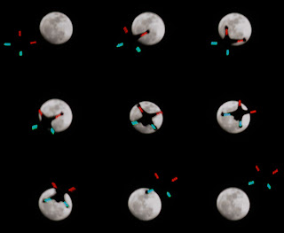
| Figure 1: ArduPhantom Night Flying |
The DJI Phantom has some nice air frame features: A sturdy plastic injection molded polycarbonate enclosure that keeps out light rain and resists hard impacts very well; Nice motors with simple, easy to use prop-mounts that are very unlikely to come loose in flight or get bent or broken in a crash; and very light-weight ESCs that have super bright LEDs on them for easy visual orientation at great distance, and superb night flying (Figure 1).
I also wanted a very small, lightweight, and extremely rugged FPV platform that I could carry in my backpack when I go hiking. The DJI Phantom air frame seems perfect for this, as the propellers are extremely easy and fast to remove, and once removed the rest of the aircraft can be stuffed in my backpack as is, and is sturdy enough to not worry about it being damaged during the trip.
But, since I'm a fan of ArduPilot, and like to be able to perform complex auto missions and make modifications to the code, I decided to build a DJI Phantom air frame with an APM flight controller. The result was very successful, and I encourage you to do the same, following the instructions below.
Materials
For this build, you will need the following parts. Fortunately, the DJI replacement parts needed can all be purchased quite cheaply. My budget for this entire project was about $600.
1x DJI Phantom replacement case kit
1x DJI Phantom replacement screw kit
1x DJI Phantom connectors kit
2x DJI Phantom ESCs (green)
2x DJI Phantom ESCs (red)
4x DJI Phantom motors
2x DJI Phantom props (set of 1 CCW and 1 CW)
1x DJI Phantom landing gear
1x APM 2.5
1x 3DR Power Module
1x 3DR GPS module
Power System Wiring
First you'll need to mount the ESCs and motors in the case, and wire up the ESCs to the output side of the power module. When mounting the ESCs, be sure the green ones are at the front end of the aircraft (the battery door end), and the red ESCs in back. If you put the red ESCs in front instead, then the signal leads won't reach, because they are of different lengths.
There is not much space inside the case for a lot of wiring and connectors, so I just cut off the XT60 connector from the output side of the APM power module, and soldered the connection directly, insulating with heat shrink of course. If you plan to use an internal battery, make sure the wiring doesn't cross over the central area where the battery goes, because it will snag on the battery when you take it in or out, and it's already a fairly tight fit for the battery as is.
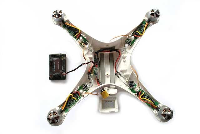
Also, be sure to keep all the wiring as low in the bottom of the case as possible, so the magnetic fields from high-current wires will not interfere with the autopilot's magnetometer (Figure 2).
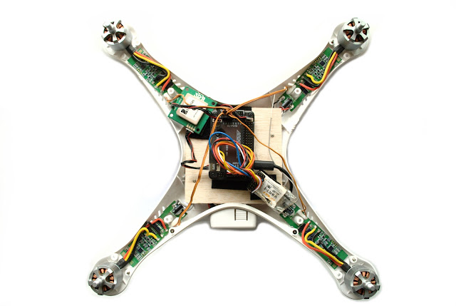
At first I velcro mounted the autopilot, GPS, and receiver to a thin wood plate which I screwed on to the four screw bosses protruding from the case bottom. This held it high enough above the power wiring below to avoid magnetic interference. However, I found that this piece of wood was basically a sounding board for vibration. Even adding foam between it and the autopilot wasn't enough to reduce the vibration to a reasonable level to get good accelerometer readings (Figure 3).
Later I found that a soft plastic cottage cheese lid made of Low-Density Polyethylene (LDPE) is a great way to mount the APM, since the soft flexible material helps to dampen vibrations (Figure 4).
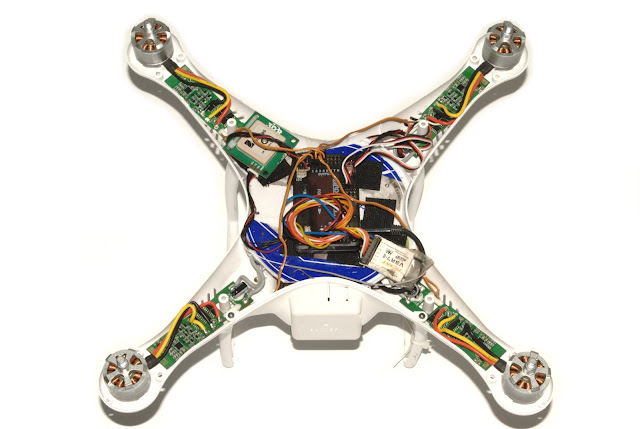 |
| Figure 4: APM mounted on LDPE food lid greatly reduces vibration |
Once you get the case on you won't want to remove those 16 screws every time you need to upload the latest version of ArduCopter, or download a flight log. So you should probably make a short USB cable that permanently connects to the APM, as shown connected in figures 3 and 4 above.
LED Connection
You won't be able to see the status of the armed and GPS lock LEDs once the APM is enclosed in the case, so you'll want to connect a couple external LEDs that you can view through the tail light port on the Phantom case. Connect one LED to A4 and one to A6 (you can also connect a buzzer to A5 if you want). Signal goes to the + side of the LED, and ground to the - side. Remember to include resistors in series with each LED to drop the voltage to the proper level for the LEDs you are using (Figure 5).
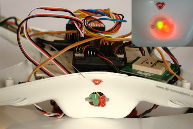 |
| Figure 5: Armed and GPS fix LEDs visible through tailight port |
You'll also need to go into Mission Planner and change the LED_MODE to 11 (the default is 9 for some reason).
Final Assembly
You can now put the top of the case on (attached with the twelve M2.5x5 and four M2.0x8 screws from your screw pack). Once you calibrate and configure everything in Mission Planner then you should be ready to bolt on the props and go fly (Figure 6)DJI phantom
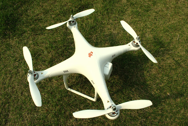 |
| Figure 6: Ready to Fly |
Flight Testing
I added a GoPro, a 5.8 GHz video transmitter, and a 3DR telemetry module for some FPV flying during a Sunday hike in the mountains. Here's the results of the first test:
It flies very nicely, even in auto modes. The main issue is shakiness and vibration of the recorded video. Hopefully I can reduce that with some tuning, better camera mounting, and perhaps stiffer props.
Comments
Hello, does this guide also apply to the Phantom 2 or is it only for the Phantom 1? I want to install an ultrasonic sensor that looks at the ground because i want the phantom 2 to fly at very accurate height. is this possible?
Thanks David,
It looks like the P2 ESC boards are a bit more complex.
I may need to reconnect the Naza and try to debug the signals that end up on the wires going to the ESC / Led boards.
I've cross posted the same question to a few other forums, so perhaps someone else has the data I need (fingers crossed)
Thanks
Roger
Hi Roger,
I made my ArduPhantom from spare parts, no conversion, so I never had an actual Phantom LED. I used regular LEDs from Radio Shack, wired directly to the APM's LED pins with a voltage drop resistor on each.
Hi David,
I've made some progress on my conversion of my Phantom 2 to an ArduPhantom (APM 2.5) (I thought a Pixhawk was too new at the moment to use on something this experimental ;-)
However one thing I can't figure out is how to control the LEDs under the ESC's. They are now showing LED permanently. Before I removed the Naza I looked at the signals to the ESC's and as well as the 400Hz PWM speed control signal there was a 900Hz signal.
I don't know if the P1 has the same LED's i.e under the ESC boards, and whether if you have them, that you got them to work ?
Thanks
Roger
Did your
Thanks David.
Hi Roger,
No, I did not calibrate the stock Phantom ESCs, the stock calibration seems to work fine.
However you'll probably need to increase MOT_SPIN_ARMED and THR_MIN to something like 175 to 185.
Regards,
David
Hi,
I've a question about ESC calibration...
I'm considering mygrading my Phantrom 2 to use PixHawk, as I've had a lot of problems with the existing DJI electronics hardware.
Because, the stock RC transmitter that came with my Phantom 2, seemed to be faulty and failed after a few mins, so I've had to replace it with a Futaba T8FGS (including using the Futaba receiver unit)
But I'm also not that happy with the Naza-M FMU that comes with the Phantom 2, as they seem prone to "FlyAways", and no one knows quite why.
So replacing the Naza-M FMU by the PIxHawk seems to be a sensible option. (I've also ordered one of those, self contained, GPS trackers that is basically a mobile phone.)
Anyway, can you tell me what you did to calibrate the stock ESC's that came with your Phantom (1) ??
Do they need calibration ?
I've read elsewhere that they don't need calibration, but I can't quite see how this is the case.
Or would I need to setup the a param's file for the PixHawk, so that the speed data to the ESC's conform to what ever their inputs require.
Thanks
Roger
Just want to share.
I found out that I can also reuse the DJI Phantom LED as APM External LED Indicator. This LED are very bright even on daylight and has three colors, RED, GREEN and YELLOW. When I looked on the PINs for the DJI Phantom LED, it has VCC, GROUND, LED1 and LED2. I tried to connect it on the ground and VCC on any port of APM and LED1 to A6 and LED2 to A7 (actually there is no difference it was reverse). Setup LED_MODE = 19 on APM, 1 for Motor ,2 for GPS, 16 for battery. I also rotated the mounting of this LED because the cable is too short to reach the left side of the APM and also I won't be needing the USB port of this LED.
So far the light that I observed are:
GPS Lock = Solid Yellow
ARMED = Solid Green
DISARMED = Green Blinking/Sometimes red blinking also.
https://www.youtube.com/watch?v=m20akn4oKDY&feature=youtu.be
Your are right. Phantom is really very tippy. I'll probably design my own landing gear. I want to be shorter. Not planning to have GoPro underneath anyway but just mobius and video tx. I have some few 3d design by my self and just saving some money to buy good quality 3d printer. :D. I feel shapeway is expensive in a long run to print all my prototype design.
My last autotune didn't go well because of little bit wind outside. I will try tomorrow again. For now I need to open again the phantom to remove some dirt then went itside after tipping and also install Teensy 3.1 for APM telemetry.
Doing autotune may make it easier to control during landing. It does take some practice though. Also you should definitely swap the landing gear for something with a wider stance. The Phantom stock landing gear are really tippy. I like some of these landing gear options:
http://www.shapeways.com/model/1075118/simensays-foldable-landing-g...
http://www.shapeways.com/shops/maikelsdesign
-
1
-
2
-
3
-
4
-
5
of 6 Next