jDrones NEWS: IOBoard goes MAVLink 1.0
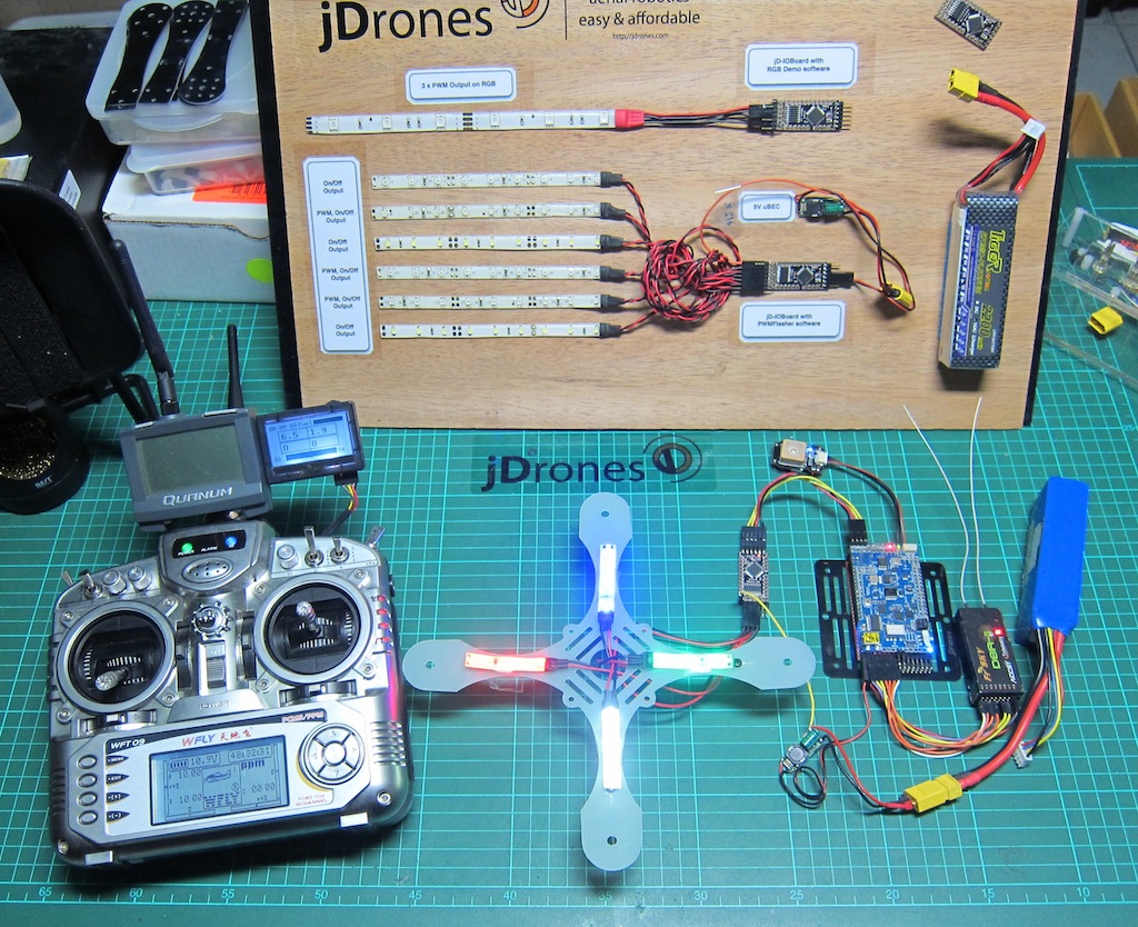
Time has come to make another exciting release. New software has been released for our mini IOBoard. With this software you are not anymore depending on static flashes, blinks and other patterns.
We made blog post about basic jD-IOBoard few weeks ago and you can read it in here. Now it just get's better and better.
jD-IOBoard now listens full MAVLink 1.0 protocol and acts depending on flight modes. Currently we are supporting ArduCopter and ArduPlane style flight modes but more has been planned. Basically all MAVLink compatible systems works fine with this.
Big thanks to Michael Oborne for his great jD-IOBoard Confgurator program that allows users easily to configure and test play different patterns. Michael is the man behind Mission Planner and also OSD Configurator.
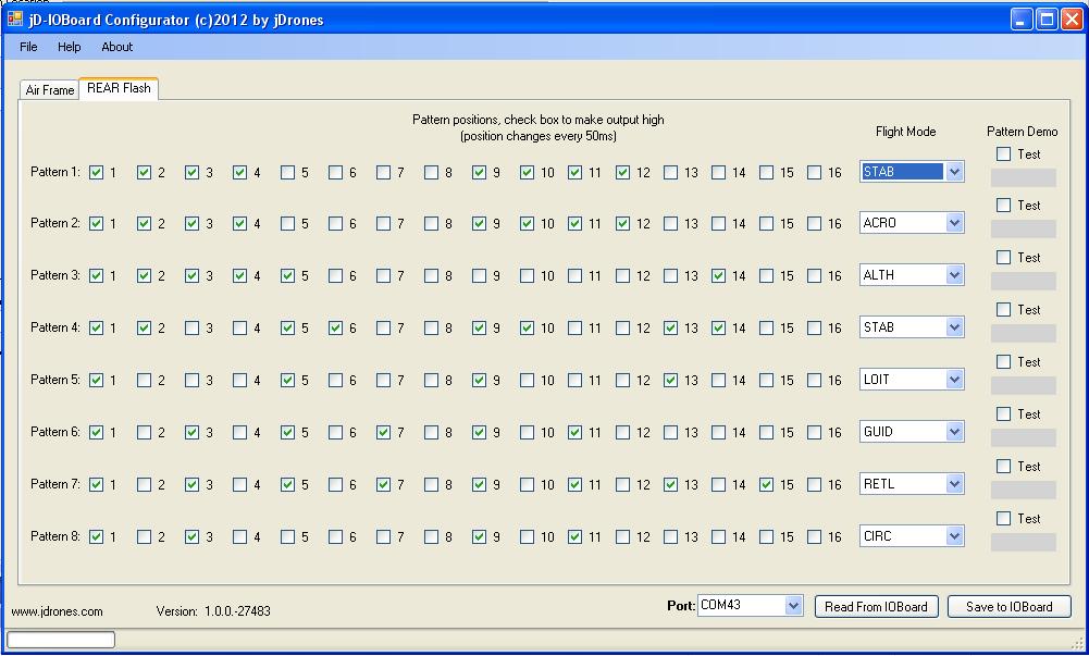
On configurator you can create 16 step patterns and 8 patterns that can be binded on different flight modes. On right hand side of every pattern you have Test box where you can simulate your pattern. Just click Test and then change on/off positions to get your desired outcome.
With Configurator you can also upload our latest HEX files from Arducodes repository.
Here is quick demo video of how it works in real-life with 3 different patterns.
Currently we are only allowing REAR pattern to be changed but in future there will be others coming too.
You can always find latest HEX and other files from our: Arducodes repository (jD-IOBoard 1.4 MAVLink. HEX)
Latest Configurator can always been downloaded from our: Software repository (Setup.EXE). Setup file is available on our Arducodes repository too.
Configurator has builtin update feature installed so it will make sure that you always have latest version of it. Source code is on our repository.
jD-IOBoard can be found from our store at http://store.jdrones.com and also from our distributors around world.
Have fun with your flashing lights. Evenings are getting darker but planes and copter more brighter.
Regards,
Jani / jDrones


Comments
Steve, we are doing small adapter board for it that allows easier connection sharing between telemetry, osd and ioboard. In mean while you can use our normal telemetry cable for that. Those and other cables can be found from our store on it's Cables area
Is the cable that goes from the APM to the IOBOARD available somewhere?
Currently no that I am aware off but we are working to have new configurator and also new revision of the software that allows you to modify other patterns too. But it will take awhile before we can make another release. If you or someone else is interested to help me on this, we are happy to get help and more ideas on how to expand it.
Thanks I just got the new boards and will be working on it next week. Is there any side project that gives it more features like the minimOSD board has? I would like the ability to flash the other lights instead of just the back one.
F11, you need to connect +5, GND, TX, RX from APM to IOBoard and then +12V (or lower/higher depending on your load) from battery and that's all so 5 cables in total.
Depending on your software in IOBoard, lights will not come out until you have +12V connected and also telemetry. This is case if you use MAVLink softwares from our repo.
OK one is definitely defective. It ended up smoking near the corner of the 2003A chip. I can send you a photo if you want to see. So I set up the second one and it appears to be working. It powers up either via the telemetry cable or the ftdi. I did Update Firmware in Configurator and chose jD_IOBoard_1.4_MAVLink.hex and it updated fine. The problem is only 2 of the LED pins will light up an LED. I'm powering it like this:
according to this picture
bottom left is my 16v, to the right of that is my negative.
above that nothing connected
the next 4 I have my 4 LED strips, red, green, blue, white. O4-O1
top pin, nothing
This is what is happening though:
First I plug in the 16v. No lights come on.
Then I plug in the FTDI and still no lights but I can communicate and upload my 8 patterns and firmware.
Then I unplug the FTDI and plug in the telemetry cable on my already turned on APM2. Right away the lights come on but only 2 of them. I've confirmed all 4 strips are working.
I also tested the amp draw on the lights and they are each around 75ma. I recall reading somewhere that you could put up to 500ma on each pin so that should be ok.
Looking closer at the schematic, I'm not sure if I'm connecting the 16v correctly. The bottom most left pin on the schematic is where I have the 16+ going to and the negative just to the right of it where it says High Power Drain output pins, O1-O6. Is that correct?
What is strange is I only get some lights when I connect to the telemetry port that has a common ground with the LOAD input. When I plug into ftdi nothing comes on.
OK to get things working, I removed the J1 jumper and put the BEC on the input side. That got it to boot and I guess I don't need any power on the output rail because it just has the signal wires going to the 4 ESCs.
So then I connected the telemetry cable from the APM2 and all the lights on the APM go out like it's dead. I unplug it and all is ok again. There seems to be a problem with this IOboard but I need some help here to diagnose it. I bought two so I'm going to hook up the second to see if the problem is the same. It says the tester was Gap.
According to this: http://code.google.com/p/arducopter/wiki/APM2board it seems like I don't have the jumper on. The APM only powers up via USB. I thought maybe the diode next to JP1 was burned but it looks ok and don't know why it would have got burned anyway. I just disconnected the telemetry cable from the xbee and plugged it to the ioboard. Then I noticed my APM2 wasn't powering up unless I used USB cable. I've always left the jumper on and regularly plug it in via USB and power the output rail with a castle 10A 5v without a problem. To get around this problem can I just bridge the input and output rails 5V+-?. Also need to know how to connect xbee and ioboard at the same time or does ioboard have to go to i2c bus in telemetry is being used for xbee?
Jani, I just received my ioboard and hooked it up to my APM2 but something seems to be wrong. I connected it like this. 4S lipo on rail with LEDs and I hooked the cable that was going to my xbee from my APM2 to the ioboard. In other words I replaced my xbee with the ioboard. I still need the xbee working so my next question is how to have them both? Do you have a wiring diagram including APM, xBee and ioboard?
After I connected them and then plugged main lipo in, the APM didn't boot. I checked around but didn't see anything wrong so I plugged in the USB cable and the APM came alive and all was normal but only when I;m plugged in via USB. I'm using a castle BEC which is powering the main rail and I check that it's outputing 5v. It all seems fine but APM doesn't power up except by USB. Could I have blow something plugging in the IOboard to the telemetry port.
Sure I can add those too on diagrams. D5,D6 are also used for Software serial so they are occupied already for "higher good" :)
-
4
-
5
-
6
-
7
-
8
of 8 Next