jDrones News: jD-IOBoard v1.0 update
You had some problems on driving LED strips or something else?? Well no problems anymore.... We have seen people making all type of darlington/transistor and similar hacks to drive their LEDs, Sirens and so on but they all need a lot of hacking and they might not be suitable for long term solution.
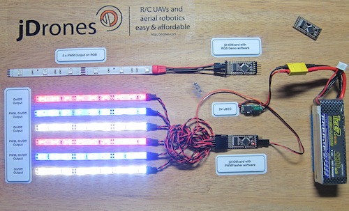
We answered on this call and made fully Arduino compatible called jD-IOBoard that can run Single LEDs, LED Strips, Loudspeakers, Buzzers, Power switches and so on. It's upto your own imagination on what all you can control with this board.
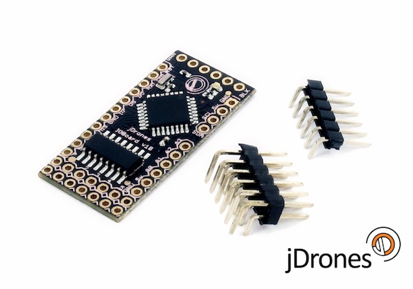
So what does this board actually do?? It has fully Arduino compatible ATMEGA 328 MCU and Darlington array to driver high power outputs. Also I2C pins are exposed and same as many TTL level IO and Analog pins. As you can see from picture above.
Board has:
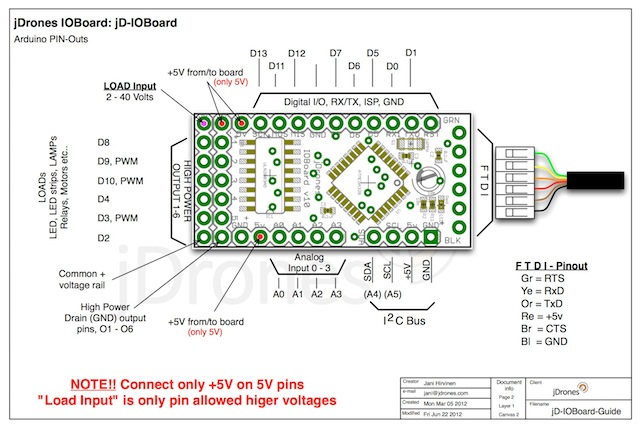
- 6 x High power outputs, max. 500mAh / 50 Volts
- 4 x Analog inputs (6 if you don't use I2C port)
- I2C port for controlling, listening I2C messages
- 6 x TTL level GPIO pins (8 if you don't use FTDI)
- 1 x FTDI port
3 high power outputs can also be controlled by PWM output while another 3 are just normal "On/Off" outputs
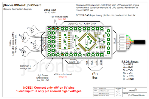
How those Arduino pinouts looks like:
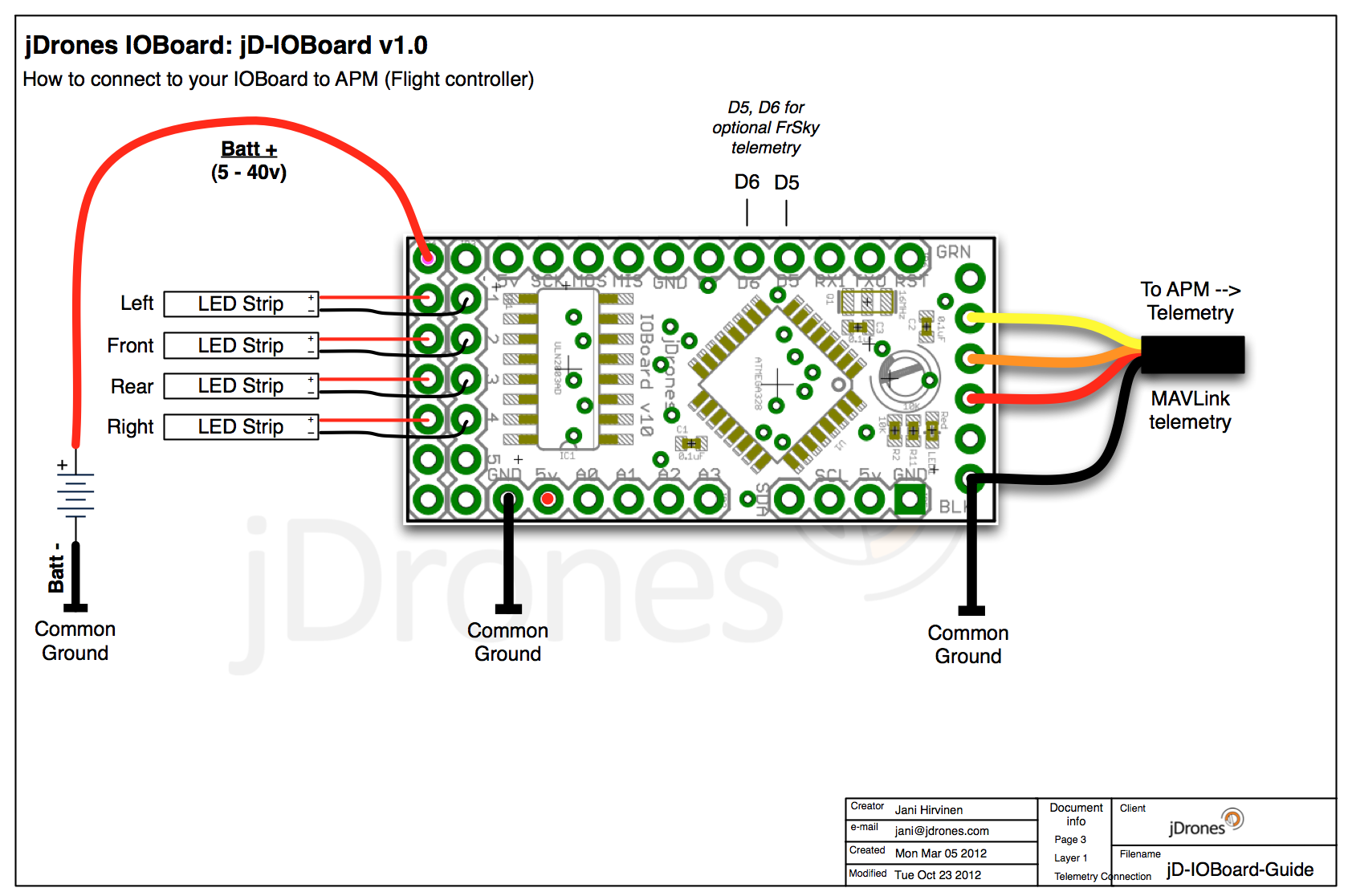
Connecting LED's,Buzzers etc is really simple. Just use one of output pins on end of the board. Below you can see examples on how to connect LEDs or LED Strips on it.
Pictures does not give enough credit for how it works so we made small video to show just few examples on how to use it. There are many other ways to do it but this should give at least some idea what/how to run it. So have fun watching it.
Get yours from jDrones Store: jD-IOBoard and have a blink blink.
Ps. There are some nice features coming to this board shortly...
Comments
Got my board this morning... but I cannot get the configurator to talk to the board.. "Failed to talk to bootloader", I am connected to the board via FDTI adapter and the board LED is lit... If I monitor the serial port then I get message "Freemem: 485" then a lot of gobblygook.. port is set at 57600 8,n,1..
Is there anything else I can try ?
Jani, most of the time I'm waiting a minute or so for a GPS lock and I would rather not use the battery too much on the LEDs. Is it possible that until you arm the copter that the left right and front lights do short quick flashes instead of staying on solid?
Also since flying with this and changing modes between stable, alt hold, loiter I've noticed the blue light will sometimes get stuck on solid. (blue is my status back light). The only fix is to land and disarm and rearm. Is this a bug or am I stumbling on a hidden feature :)
And what can the 5th and 6th high power pin be used for?
Jani do you have a diagram showing what each light's position is. For example which pin is the flashing mode light? Which is the front light, right and left? And what are the extra 2 pins for? Hexa? I'm just playing with it connected via FTDI and have uploaded my flash sequences but am not sure which light is which.
F11, there will be new configurator coming soon that will allow better to position several outputs. For now easiest way to have multiple outputs for now is just to connect extra strips to output pins eg 2 strips on one output. So to have them on + more is easy when doing this way.
Jani, I got the new ioboards and one is set up and working great. The other I will check tomorrow. My quad is in X configuration but I would like to do my lights like this:
Green on right side of front right arm and right side of lower right arm.
Red same way on left side.
White on the inside of the front two arms and Blue and the back inside two arms.
In this case should I use the Air Frame in configurator for + or X config? The way I want the lights is more like the + configuration since I will do them so that each arm has one color on one side of the arm and a different color on the other side of same arm.
ravi, yes you can use ArduCAM OSD configurator to upload hex file too to IOBoard but as you said, don't hit read/write buttons as it will expect OSD settings. Naturally OSD settings will not work with IOBoard. Fimrware upload functions are same between OSD and IOBoard configurator programs.
Telemetry does NOT go to I2C ports, it goes to normal FTDI port just like on OSD. I2C is for extra use and future expansion only.
hi jani, i found a easy way to upload hex files to jd_ioboard. i used the arduOSD configurator to uplaod the hex file to ioboard. it works perfectly. do not read or write the board. just select the com port and select upload firmware from the 'options' menu in the arduOSD configurator. it uploades the selected hex file within seconds. now one question the Tx wire from the telemetry port has to go to 'SDA' or 'SCL' of I2C port of the jd_ioboard?
thanx jani, sounds little complicated so will use the io_board_mavlink1.4 .hex file generated by u. i will use a AVR programmer.
Ravi, you have all nesessary library etc files in same repository as the main code too. Libraries are under library folder.
hi jani, thanx for the importat information. since APM2 is uploaded through mission planner so had been out of touch with arduino compiler. i was able to get into compiling mode through arduino1.0 but i get compilation errors. i think i am missing some associated files with the jd_ioboard_mavlink.ino. can u please send a link so that i have all the files in the associated files sketchbook.
-
17
-
18
-
19
-
20
-
21
of 24 Next