jDrones News: jD-IOBoard v1.0 update
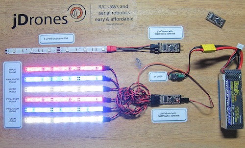
You had some problems on driving LED strips or something else?? Well no problems anymore.... We have seen people making all type of darlington/transistor and similar hacks to drive their LEDs, Sirens and so on but they all need a lot of hacking and they might not be suitable for long term solution.
We answered on this call and made fully Arduino compatible called jD-IOBoard that can run Single LEDs, LED Strips, Loudspeakers, Buzzers, Power switches and so on. It's upto your own imagination on what all you can control with this board.
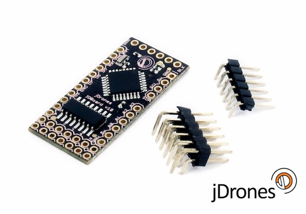
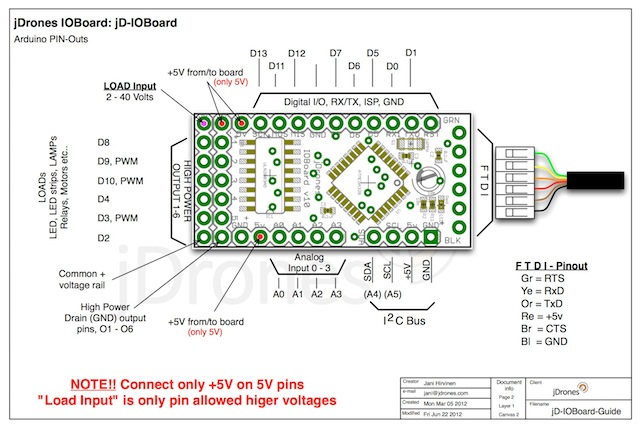
So what does this board actually do?? It has fully Arduino compatible ATMEGA 328 MCU and Darlington array to driver high power outputs. Also I2C pins are exposed and same as many TTL level IO and Analog pins. As you can see from picture above.
Board has:
- 6 x High power outputs, max. 500mAh / 50 Volts
- 4 x Analog inputs (6 if you don't use I2C port)
- I2C port for controlling, listening I2C messages
- 6 x TTL level GPIO pins (8 if you don't use FTDI)
- 1 x FTDI port
3 high power outputs can also be controlled by PWM output while another 3 are just normal "On/Off" outputs
How those Arduino pinouts looks like:
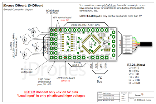
Connecting LED's,Buzzers etc is really simple. Just use one of output pins on end of the board. Below you can see examples on how to connect LEDs or LED Strips on it.
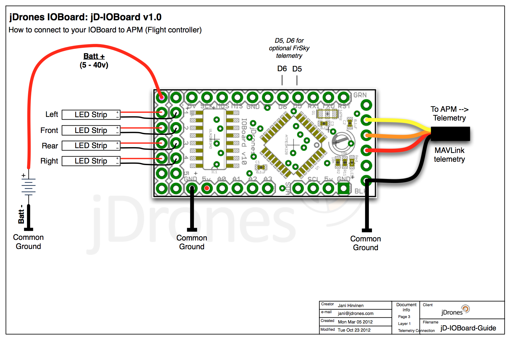
Pictures does not give enough credit for how it works so we made small video to show just few examples on how to use it. There are many other ways to do it but this should give at least some idea what/how to run it. So have fun watching it.
Get yours from jDrones Store: jD-IOBoard and have a blink blink.
Ps. There are some nice features coming to this board shortly...

Comments
Hello jbabio,
Thanks for your response.
One more question. Do you have any extra sensor for the "Lipo"'s voltage? This is also displayed?
greetings,
Anderl
Yes it is. I've have the issue with Latitude displaying and sometimes phantom values appear briefly on RPM (no sensor installed), Speed or other values.
Does someone tried it with the original FLD-02 from frsky? could someone confirm or not if the GPS data is showed correctly on the original screen?
Hello jbabio, a question please,
You have the er9x Frsky firmware and the telemetry info is directly displayed on your 9X screen, yes?
i am using JDioboard on plane with LED strips on wing. the LED board has a simple arduino code to make them blink randomly. does anyone has a code so that they blink according to the battery voltage. the ideal would be that the blinking frequncy increases as the voltage comes down so that you can know when to land the plane. it would be very helpful. these bright LED stips are visible throughtout the flight so voltage can always be monitored.
I have the JD-IOboard installed on my system with the FrSky firmware connecting the APM 2.0 to the FrSky D8R-II Plus. The system also has Xbee telemetry for APM planner but I use FrSky telemetry to display RSSI and other data on my TX when I'm not in front of the PC.
The TX is a Turnigy 9X with FrSky DHT, TelemetrEZ board and latest er9x FRSKY build.
The telemetry (xbee) on the APM planner works OK and the "translation service" of the JD-IOboard works but not at 100%.
For example the GPS shows correctly the Longitude but the Latitude is completely wrong (incorrect symbols and even the numbers are wrong)

Does someone has the same problem?
Veikko, can you download and test jD-IOBoard MAVLink 1.5 from download area at our repository to see if that works for you. At here http://code.google.com/p/arducodes/downloads/list I made modified firmware to test it.
@Veikko, we are testing latest configurator with several different FTDI drivers to see if that causes problems on writing.
@Steven how easily is always depending on programming skills but in generally not too difficult. You don't need to know so much about MAVLink protocol itself just basic programming skills are enough. IOBoard software is quite simple and rather straight forward to read.
All arm/disarm, GPS lock etc are already seen by main code so basically you just need to change light patterns on program it self and nothing else.
I'm not too bad at coding with Arduino, but not too familiar with MavLink yet.
How easy would it be to modify the exisitng code to do the following.
The principle seems simple, just not sure how to integrate this into the MavLink code, any help would be very much appriciated.
Here is the link to my existing code and a video of what my pattern currently does.
Custom Nav Lights Arduino Code
https://www.youtube.com/watch?v=XYQc70F1NMs&sns=em
That's odd but I will look that and upload new HEX if that's the case and if that's the case, there will be new HEX.
-
5
-
6
-
7
-
8
-
9
of 15 Next