jDrones News: jD-IOBoard v1.0 update
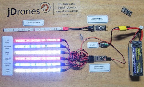
You had some problems on driving LED strips or something else?? Well no problems anymore.... We have seen people making all type of darlington/transistor and similar hacks to drive their LEDs, Sirens and so on but they all need a lot of hacking and they might not be suitable for long term solution.
We answered on this call and made fully Arduino compatible called jD-IOBoard that can run Single LEDs, LED Strips, Loudspeakers, Buzzers, Power switches and so on. It's upto your own imagination on what all you can control with this board.
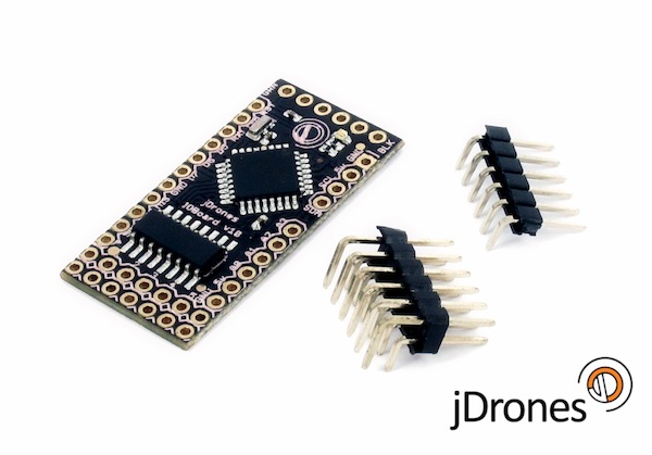
So what does this board actually do?? It has fully Arduino compatible ATMEGA 328 MCU and Darlington array to driver high power outputs. Also I2C pins are exposed and same as many TTL level IO and Analog pins. As you can see from picture above.
Board has:
- 6 x High power outputs, max. 500mAh / 50 Volts
- 4 x Analog inputs (6 if you don't use I2C port)
- I2C port for controlling, listening I2C messages
- 6 x TTL level GPIO pins (8 if you don't use FTDI)
- 1 x FTDI port
3 high power outputs can also be controlled by PWM output while another 3 are just normal "On/Off" outputs
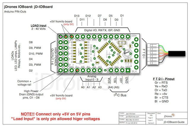
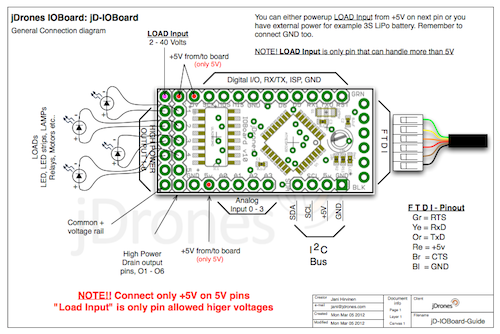
How those Arduino pinouts looks like:
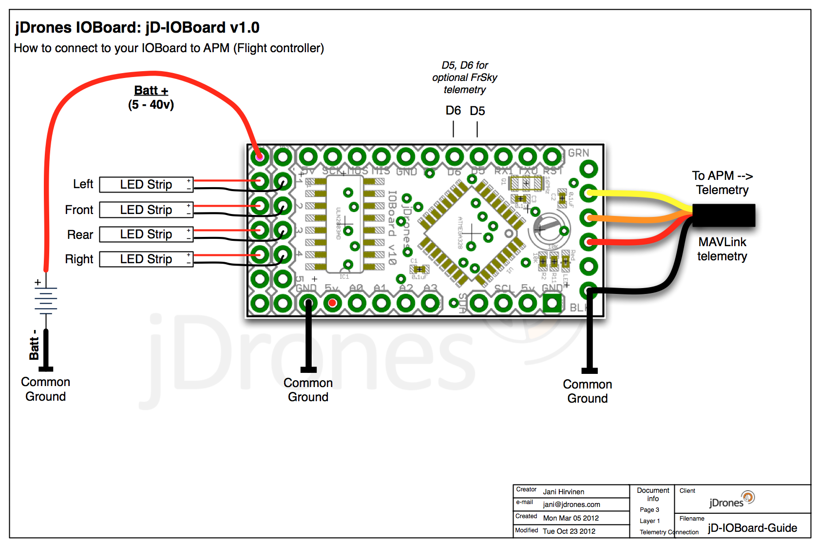
Connecting LED's,Buzzers etc is really simple. Just use one of output pins on end of the board. Below you can see examples on how to connect LEDs or LED Strips on it.
Pictures does not give enough credit for how it works so we made small video to show just few examples on how to use it. There are many other ways to do it but this should give at least some idea what/how to run it. So have fun watching it.
Get yours from jDrones Store: jD-IOBoard and have a blink blink.
Ps. There are some nice features coming to this board shortly...
Comments
I'm having fun with the IOBoard and some LED strips on my octo. I've never coded any Arduino, so figuring out some custom code for the IOBoard is a nice introduction (I'm not new to coding).
My questions are this:
1) I understand that only 3 of the 6 output are PWM. Is there any way to extend this? It'd be awesome to have all LEDs "breathe" when the system is disarmed. Right now I can only get that effect on three of the strips.
2) I'm struggling to understand how to grab and decode the MAVLink messages. I've studied Jani's example code but I don't know what the various byte messages correspond to. What I'd like to do is parse the armed/disarmed state, the GPS lock state, and the flight mode. I'll combine these into a composite pattern. However, as of now, I don't know what the MAVLink message will look like when these states are changed. Any ideas?
3) Jani mentioned that the additional output could be used for other purposes, but they are all only 5V. What would be involved in using these outputs to control more LED strips? It'd be awesome if all 8 arms could have their own independently controlled LED. I don't have much electronics experience, but perhaps the low power outputs could be used to drive relays which passed on the high power signal?
Thanks, Josh
Mr Jani you have to make a detail manual, guide or procedure or documentations on how to setting up this ioboard and detailed procedure and troubleshoot guide from A to Z up until its realy realy work and functioning on the Configurator !! we all pay for the iobard and its not free..!!! hope you understand !!
i have give up with this ioboard !! now my ioboard is having bootloader problem and my pc cannot detech the ioboard this problem occure wehn i clear the ioboard EEPROM using Arduino IDE now i cannot update and upload the firmware is this problem i'm getting cause the ioboard faulty ?? or any detailed procedured to make it work again ??
Problem is that if you connect all RX/TX cables as 1:1 then radio modem will get double messages and it gets stuck. This same thing happens if you connect OSD and radio modem.
I am working to have solution for this and there will be small distribution board coming shortly that will solve it. We already have test boards and now finalizing it's design.
Problem is not in IOBoard it's more or less problem on MAVLink protocol and we have been talking about how to solve this problem in bigger scale several times on our development meetings. As MAVLink protocol does not support multipoint transmissions yet.
Bob, we are working on new release of IOBoard software that should fix this issue. There seems to be few variable problems on first our beta release for FrSky software. Hopefully on same time we can show our new FrSky display too.
I would love to know if somebody resolved the issue of GPS display on FrSky since this is the main reason I got the board latitude and longitude is reversed but this would be nothing if one of the data wont be corrupted. We are several to got this problem and got no support from Jani so far despite several request.
Jani, I couldn't find any shipping information on your website. What kind of shopping costs do I have to expect for an I/O board or 2 to Finland? Do you by any chance have a "warehouse" here?
for your info im using Dfrobot FTDI Basic breakout board to program the ioboard
what is the pin assignment on the APM telemetry port ..?
-
10
-
11
-
12
-
13
-
14
of 24 Next