jDrones News: jD-IOBoard v1.0 update
You had some problems on driving LED strips or something else?? Well no problems anymore.... We have seen people making all type of darlington/transistor and similar hacks to drive their LEDs, Sirens and so on but they all need a lot of hacking and they might not be suitable for long term solution.
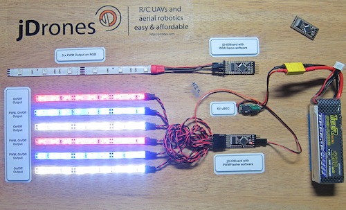
We answered on this call and made fully Arduino compatible called jD-IOBoard that can run Single LEDs, LED Strips, Loudspeakers, Buzzers, Power switches and so on. It's upto your own imagination on what all you can control with this board.
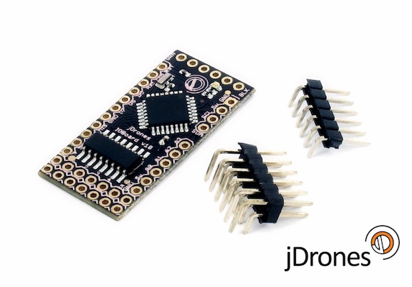
So what does this board actually do?? It has fully Arduino compatible ATMEGA 328 MCU and Darlington array to driver high power outputs. Also I2C pins are exposed and same as many TTL level IO and Analog pins. As you can see from picture above.
Board has:
- 6 x High power outputs, max. 500mAh / 50 Volts
- 4 x Analog inputs (6 if you don't use I2C port)
- I2C port for controlling, listening I2C messages
- 6 x TTL level GPIO pins (8 if you don't use FTDI)
- 1 x FTDI port
3 high power outputs can also be controlled by PWM output while another 3 are just normal "On/Off" outputs
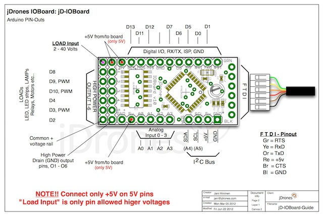
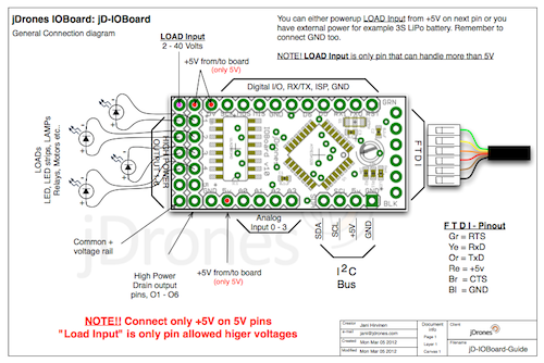
How those Arduino pinouts looks like:
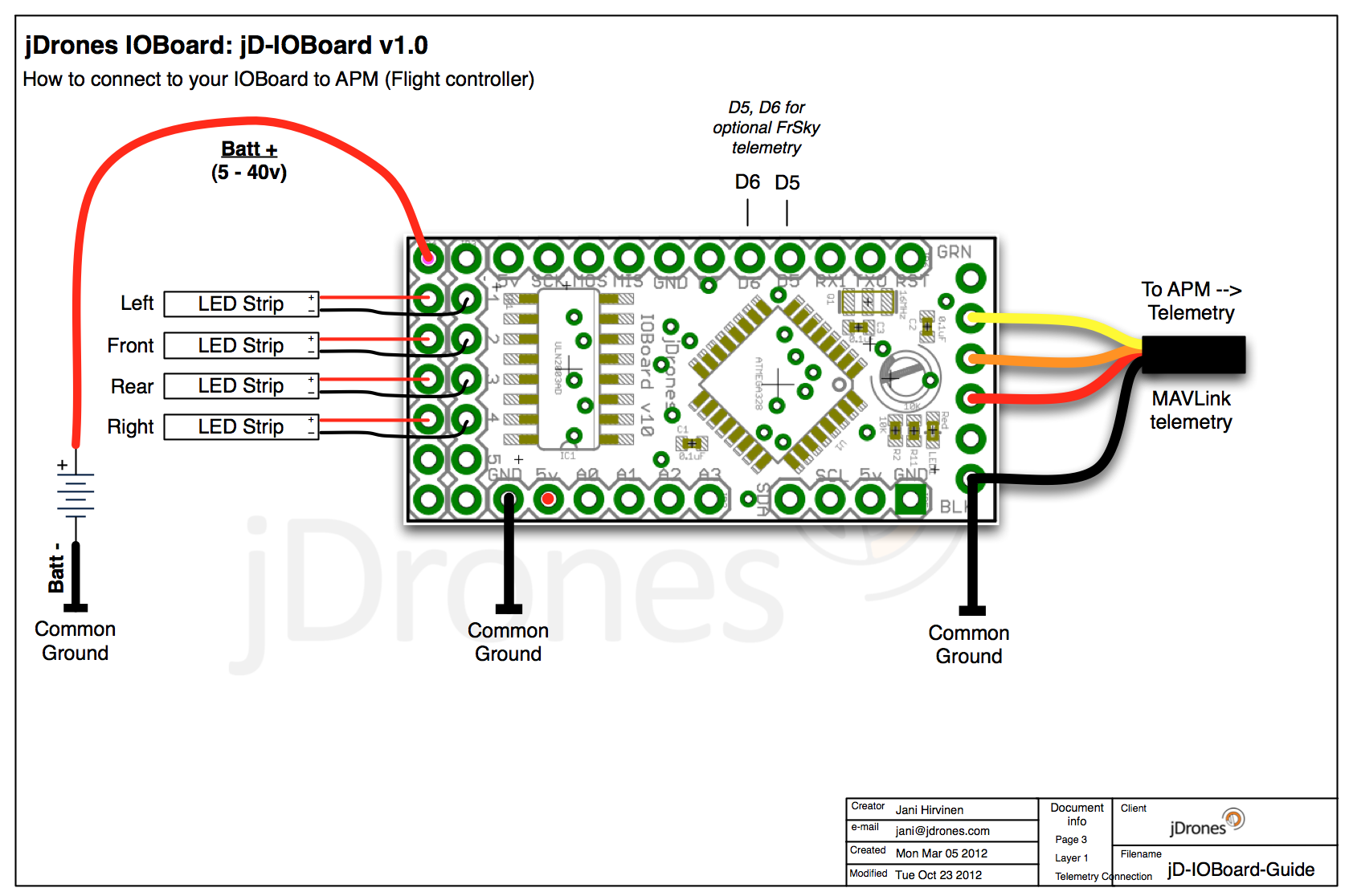
Connecting LED's,Buzzers etc is really simple. Just use one of output pins on end of the board. Below you can see examples on how to connect LEDs or LED Strips on it.
Pictures does not give enough credit for how it works so we made small video to show just few examples on how to use it. There are many other ways to do it but this should give at least some idea what/how to run it. So have fun watching it.
Get yours from jDrones Store: jD-IOBoard and have a blink blink.
Ps. There are some nice features coming to this board shortly...
Comments
After the hard work and research at last i have Succsessfully bring up my ioboard bootloader and now my ioboard is alive again but again still cant assign the LED pattern :(
well !! guest have to purchased new ioboard or ...??? is there any other product out there ..?? that have same function with ioboard ..??
@ mohd fitri - I wish you luck, I , with many others, have been trying to get an answer from jDrones on this issue, for nearly 3 months in my case.
I too have tried to burn the bootloader via AVR Studio and also by following the offered tips re using an Arduino - it doesn't work.
Clearly jDrones have had this problem since the outset - problem first raised on this forum in August last year - yet they continue to sell it without any further advice on its use.
I've had better customer service from HobbyKing !!
Still no luck to recover the bootloader..!! for your info i'm using Arduino Uno to burn the boot loader and confirm the MISO MOSI connection is correct..!!
Jani can u show me diagram for the wiring and pin assignment from the ioboard to the ISP program card
i/e : from ioboard RxD / TxD / +5V / CTS / GND to ISP Program card MISO / MOSI / RESET / GND / +5V
Thanks for pointing me towards the other software, Jani. I was looking at the very simple examples and not the more detailed *_FrSky_* and *_MAVLINK_* files. I think I found everything I was looking for in jD_IOBoard_MAVLink
Thanks!
jg
Thanks Jani i will try !!
and documentation or manual for the procedure im new to this Arduino things
Thanks
To be more precise.
- Go on Arduino IDE and open Example Sketch called ArduinoISP.
- Connect cables as said earlier
- From Tools menu choose Programmer / Arduino as ISP
- From Tools/Board menu check that you have Arduino Pro or Mini Pro 5V/16Mhz selected
After that from Tools menu click Burn Bootloader. If cables are connected correct way it will start burning process. Process takes 10-15 seconds or so. Most common mistake is to put MISO/MOSI cables upside down so if that is the case, just swap them and try again.
There are more instruction on ArduinoISP programming sketch and also Arduino.cc website.
If your bootloader is corrupted, board is normal Arduino board and if you don't have real ISP programmer at hand you can always use another Arduino board to burn bootloader. Just connect their ISP pins together. You need to connect MISO, MOSI, CLOCK, RESET, GND and +5 between boards and then use Arduino IDE to burn bootloader.
-
8
-
9
-
10
-
11
-
12
of 24 Next