jDrones News: jD-IOBoard v1.0 update
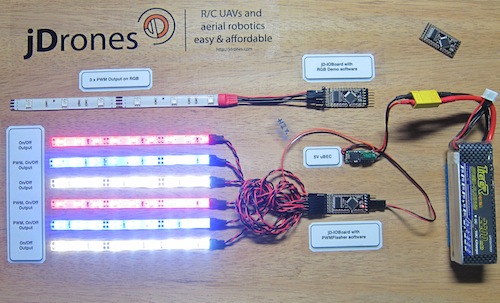
You had some problems on driving LED strips or something else?? Well no problems anymore.... We have seen people making all type of darlington/transistor and similar hacks to drive their LEDs, Sirens and so on but they all need a lot of hacking and they might not be suitable for long term solution.
We answered on this call and made fully Arduino compatible called jD-IOBoard that can run Single LEDs, LED Strips, Loudspeakers, Buzzers, Power switches and so on. It's upto your own imagination on what all you can control with this board.
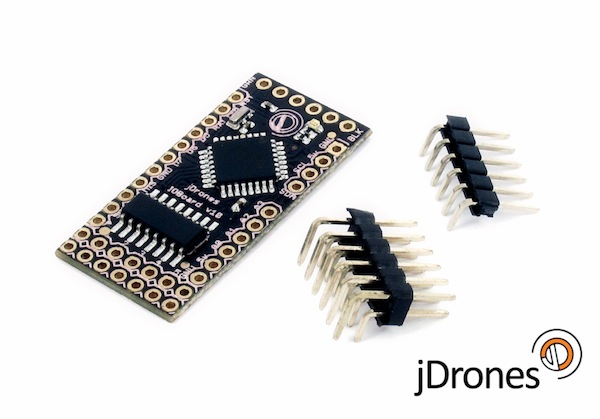
So what does this board actually do?? It has fully Arduino compatible ATMEGA 328 MCU and Darlington array to driver high power outputs. Also I2C pins are exposed and same as many TTL level IO and Analog pins. As you can see from picture above.
Board has:
- 6 x High power outputs, max. 500mAh / 50 Volts
- 4 x Analog inputs (6 if you don't use I2C port)
- I2C port for controlling, listening I2C messages
- 6 x TTL level GPIO pins (8 if you don't use FTDI)
- 1 x FTDI port
3 high power outputs can also be controlled by PWM output while another 3 are just normal "On/Off" outputs
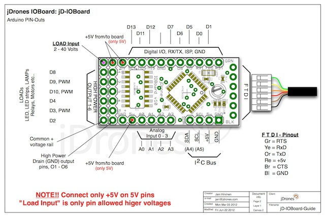
How those Arduino pinouts looks like:
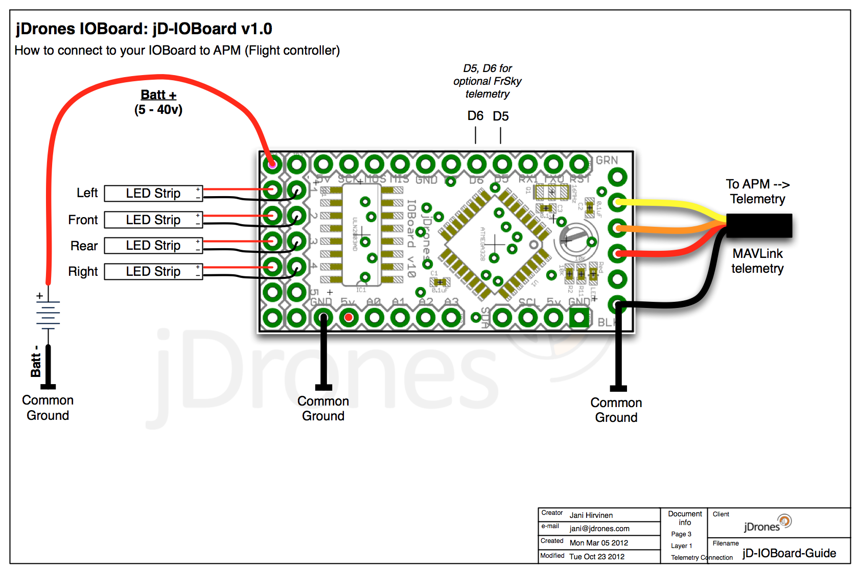
Connecting LED's,Buzzers etc is really simple. Just use one of output pins on end of the board. Below you can see examples on how to connect LEDs or LED Strips on it.
Pictures does not give enough credit for how it works so we made small video to show just few examples on how to use it. There are many other ways to do it but this should give at least some idea what/how to run it. So have fun watching it.
Get yours from jDrones Store: jD-IOBoard and have a blink blink.
Ps. There are some nice features coming to this board shortly...
Comments
Greeting Jani mine bootloader already corrupted how to fix it Thanks !!
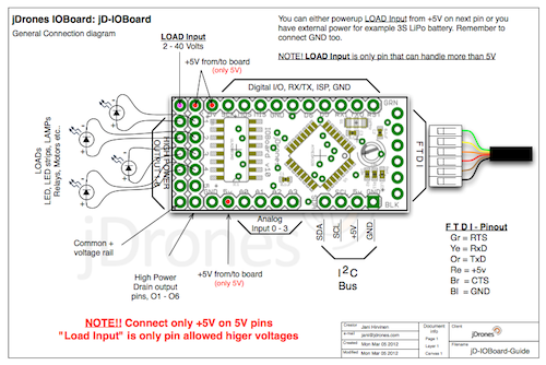
Ravi, sorry to hear your problems but there are big red warnings all around the documentation images not to connect high power to 5V area. As we tried to keep it's production price as low as possible and also physical size, it does not have regulator like we have on MiniOSD and because of this current design needs both +12v and +5v to work properly. Next revision will at least have better high voltage input with cable.
MAVLink / Flying mode and flashed pattern you can change with IOBoard Configurator. Both Configurator and MAVLink software are still on their beta stage, new features will be coming on those. Also they are full opensoftware so anyone are free to modify those.
But sure all ideas and proposals are welcome.
jani, i have bad experince with ur LED board. the board does not works when you power the digital side via APM and the LED driver side bia the 12 V battery. the only way to make it work is make a common ground for analog and digittal sides. since the connectors do not have polarity protection i gave +12V to ground of analog side by error and my brand new APM2.5+ fried instantly. you should come up with a better product and with better documentaion. the LED blinking seqencee has no documentaion to show what parameter of mavlink is being indiacted by LED patterns. i hope to see the version has a failsafe od protecting the APM.
Josh did you look IOBoard FrSky software there?? as in FrSky software there is full MAVLink stack included and it looks all hartbeats etc. Another that you can look is our MiniOSD software that me and Sandro wrote earlier. Now Gabor and others are continuing that software.
Thanks, Jani. I've actually studied the beta software that you mentioned and know which outputs are PWM. I've successfully used them to make the 3 PWM LEDs "breathe" up and down. Pretty cool!
However, the Mavlink messages aren't parsed as such in that software. Instead, there's just a select case type of structure based on a byte value. What I don't know is what byte values correspond to what conditions. Further, I can't tell how the armed/disarmed state, flight mode, and GPS information gets packed into a single byte. Any help on that? Thanks again!
Josh, there are 3 pwm outputs and 3 just normal IO outputs on jD-IOBoard. If you look codes at arducodes repository those pins are marked on there.
Same goes for MAVLink messages. There is already software that reads MAVLink commands as we use those on MAVLink beta software for IOBoard. That software is also on arducodes repository.
That's great information, Steven, I really appreciate it. I'll look into using the PWM library to control each of the 6 jDrones IOBoard outputs. So, the 3 existing PWM outputs on the IOBoard are PWM by virtue of hardware?
If I ever get around to building actual circuits on the breadboard (sounds fun but I have next to no electronics experience), I'll try to expand the IOBoard to control all 8 out. For now, I'll stick with the 6 outputs and have one boom light always on and one boom without an LED.
Thanks again, Steven. Now I just need to know how to parse those Mavlink messages! Anyone?!
1) Its possible to use standard Arduino outputs for PWM. However the PWM needs to be controlled in software. Search Google or have a look at www.arduino.cc and look for a Software PWM library.
3) The 6 "high power" outputs are still standard Arduino 5v outputs, but go through a ULN2003A high current Darlington array. Although surface mount on the IO board, they are available as a standard DIP package allowing you to breadboard this chip for additional high current outputs.
Hope that helps a little.
Steve
just a caution. be very careful in applying 12V LED power supply to the jd_ioboard. i accidently reversed the polarity on LED power supply pin and I fried my APM2.5. The ground pin becomes common with APM2.5 via telemetry port. so be very careful when connecting LED powers upply. the best would be to use polarity type connector or a diode on the power supply ground pin of jd_ioboard. my APM2.5 was brand new and flying really good on quad. man it hurts. the jd_ioboard needs to be improved. specailly for power supply connectors to the LEDs.
Just a slight bump for my previous questions. I'd really like to know how to grab and parse the Mavlink messages with the IOBoard.
Josh
-
9
-
10
-
11
-
12
-
13
of 24 Next