(copied from my blog at hobbyuav.com)
Hey everyone!
I have not found a place where the fixed-wing control for the PX4 is being done so I started this blog.
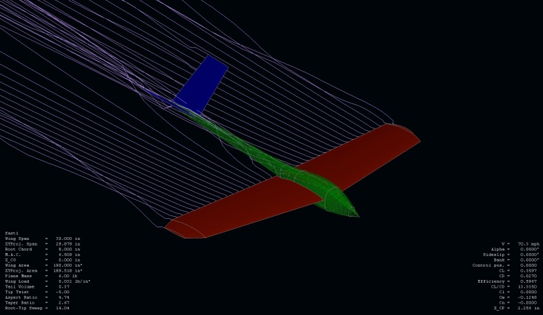
Above is a Screen shot from XFLR5. I use it to mathematically model the physical form of an airplane. I can then take this description of said plane and then start modeling the flow of air over the surfaces described is the model. You can then send modeled air at it in different angles and at different viscosity. In other words different pitches and yaws as well as different air densities or altitudes.
I use it all the time to make U.A.Vs. I think it should be integrated into the PX4 so that we can start introducing into the mathematical models of the control algorithms, a model of the crafts interaction with its environment (air). Thus achieving a much more complete mathematical description of the system.
This can be implemented by modeling the aicraft in XFLR5 then taking the results and generating LUTs of the predicted air/air-frame interactions. just one example of this would be to use the generated full airplane polar graphs to predict what AOA at a given speed and air density, should produce level flight or even produce a desired vertical acceleration (climb or dive). This would greatly reduce the dependence on the PID loop to achieve a given altitude, making the system much more stable at a greater range of the aircrafts flight envelope.
This can also be applied to different control loops as well. yaw and roll control. It can also be applied to every control surface as well. XFLR5 can generate tables of inertial moment data as well giving you a Cm polar. this can be calculated for various control surface angles. You can then take the aerodynamic Cm data and combine it with a physical inertial model to do a full stability analysis. The output of the Cm and the inertial model data can then be feed in to the control loops to achieve desired rotational accelerations instead of purely relying on the PID loop. Giving the control loops a much wider dynamic range that is possible with just a PID loop.


Comments
@J
yes I fully plan on implementing this myself into the PX4. I know this will work. Aerodynamic and Inertial modeling can be found already working on the high end closed source autopilots the military and government uses. I think it is the missing piece in every open source AP I have seen to date. 4 to 6 weeks is when I will be able to start committing. I look forward to experimenting with these ideas and proving them in the field.
Thanks for your time everyone!
Very interesting proposal, but it's easy to go overboard and take the numbers of this analysis as realistic. The actual system is much more chaotic.
Another thing we should not forget is that surface deflections take a bit of time, they're not instant and there may be some slop in the control linkage, which defines the eventual limit of how accurate and precise a system can be controlled, no matter what you measure or calculate before. The aircraft must also be built and tuned precisely to spec with equipment that can measure tenths of degrees?
It would be an interesting experiment to extend PID controllers to govern attitude through a plane's pitch/roll/yaw moments. XFLR5 could provide either an approximation or scheduling (by airspeed) of the required deflection of control surfaces to achieve these moments and the effect should be measurable by the gyro's to provide a feedback signal. Sounds like such a controller would also have a better capacity to limit exerted forces on airframes/wings, with some help of the nav module.
I can see how the "trim" settings based on airspeed help remove the need for large integrators.
@jay
my point is this will make any controller algorithm better. this would be the data going into the control loop not a part of it. The better data any controller has coming the better the data coming out. garbage in, garbage out.
edit:
"flight at all the different speeds right into. wind vanes..."
should say "flight at all the different speeds right into the AP program. wind vanes..."
@andrew
ya I think you are getting it. for thouse still a little confused. let me illustrate further....
first off. lets forget about auto pilots and loops and gains etc. lets talk about how to fly a plane at different speeds and maintain level flight. (constant altitude)
we have all experienced that a positively stable airframe will pitch up and climb if you hit the throttle. and in order to fly super slow you must pitch the nose up.
so according to XFLR5 the techpod while weighing a whopping 6.5 lbs the techpods AOA looks like this to maintain the 6.5 lbs of lift need to for level flight (constant altitude)
@93.7 MPH the techpod will need to maintain a -2.0 deg AOA
@48.2 MPH the techpod will need to maintain a 0 deg AOA (cruse speed)
@36.6 MPH the techpod will need to maintain a +2.0 deg AOA
@28.7 MPH the techpod will need to maintain a +5.0 deg AOA
this is how an airplane naturally is flown. as a pilot this happens quite automatically with out much need for thought other then you will end up adding down trim at high speeds for perfect level flight and you will have to add up trim for level flight at low speeds. the idea is to program in this pitch/speed relationship need for level flight at all the different speeds right into. wind vanes or sensor do detect AOA are not need because we are assuming and trying to maintain level flight so at 0.0 degrees of pitch relative to earth, your AOA will be 0.0 degrees and unless you are doing exactly 48.2 MPH. if you are doing more the airplane will be climbing any less you will be losing altitude.
drag really does not need to be calculated. although it may be useful for motor control. absolute drag however is vastly more complicated to calculate. XFLR5 can however produce good relative drag numbers. what i mean is they are good when compared to other drag numbers produced by XFLR5 in other word less drag is less drag. exact drag real wold numbers are much more complex to predict.
I have to agree with Philippe.
If you take the time to make a sophisticated mathematical model, a you should consider a better regulator than an PID-Regulator.
Especially when a Kalman filter is on the Roadmap the LQR is a good way to go (the LQR is similar to the Kalman filter).
Any effects modelled in the mathematical model will be considered by the LQR-Regulator (For example different movements of the control surfaces at different speed).
The LQR-Regulator is an optimal regulator. This means it is mathematical proven that there is no better regulator (for given weighting factors and the mathematical model).
As far as gain scheduling goes, I think it is nothing like it. The MBC should deliver an open-loop or feed-forward term for the control surfaces which is subsequently trimmed by a limited authority PID feedback loop. The key difference between this method and gain scheduling is that the error term does not need to even exist for action to be taken. The response time of the system to large changes in circumstances can be much faster
http://www.rcgroups.com/forums/showpost.php?p=4139374&postcount=2
Somehow that also slipped my mind.
I forgot that the IMU offset from the CG would also have to be taken into account when calculating the AOA.
-
1
-
2
of 2 Next