 for this demo I used 3.3v as power source for the receiver but in real life it will probably be a 5v power source so you'll need to figure a way how to do it (resistors, level converter...)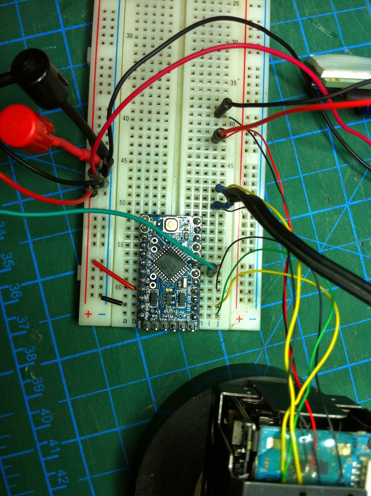


and of course the code :)
/* build and tested using
sony camera block fcb-ex11d and
rc transmitter spektrum dx6i with
ar6200 reciever and connected to the elev channel */
byte address_set[4]= {0x88, 0x30, 0x01, 0xFF};
byte if_clear[5]= {0x88, 0x01, 0x00, 0x01, 0xFF};
byte command_cancel[3]= {0x81,0x21,0xFF};
byte zoom_teleVar[6]= {0x81, 0x01, 0x04, 0x07, 0x23, 0xFF}; //zoom in 81 01 04 07 2p FF - p=0 (low) to 7 (high)
byte zoom_wideVar[6]= {0x81, 0x01, 0x04, 0x07, 0x33, 0xFF}; //zoom out 81 01 04 07 3p FF - p=0 (low) to 7 (high)
byte zoom_stop[6]= {0x81, 0x01, 0x04, 0x07, 0x00, 0xFF}; //stop zoom
byte auto_focus[6]= {0x81, 0x01, 0x04, 0x38, 0x02, 0xFF}; //auto focus
const int thisdelay= 250; //time between sets
const int zoom_out=3; //Zoom
void setup() {
pinMode(zoom_in, INPUT);
pinMode(zoom_out, INPUT);
// initialize both serial ports:
Serial.begin(9600);
//send Address set
for (int i=0; i<4; i++){
Serial.write(address_set[i]);
}
delay(thisdelay);
//send IF_clear set
for (int i=0; i<5; i++){
Serial.write(if_clear[i]);
delay(thisdelay);
}
}
//zoom in
void loop() {
int zoom_inState=pulseIn(3, HIGH, 25000);
if(zoom_inState>1550 )
{
delay(thisdelay);
//Send zoom tele set
for (int i=0; i<6; i++){
Serial.write(zoom_teleVar[i]);
}
}
//zoom out
int zoom_outState=pulseIn(3, HIGH, 25000);
if(zoom_outState < 1400 )
{
delay(thisdelay);
for (int i=0; i<6; i++){
Serial.write(zoom_wideVar[i]);
}
}
//zoom stop
if(zoom_outState < 1500 && zoom_inState > 1400 ){
//send auto focus cmd
for (int i=0; i<6; i++){
Serial.write(auto_focus[i]);
}
//send zoom stop
for (int i=0; i<6; i++){
Serial.write(zoom_stop[i]);
}
}
}
void sendcommand_cancel(){
for (int i=0; i<3; i++){
Serial.write(command_cancel[i]);
}
}
next thing will be to import it to attiny85
will release the code later tonight
**got really cool board that im using called attami (google it :) )
i was told that it will cost 1euro (not assembled)
and will be available at c31c (chaos communication congress #31)
/* build and tested using
sony camera block fcb-ex11d and
rc transmitter spektrum dx6i with
ar6200 reciever and connected to the elev channel */
#include <SoftwareSerial.h>
#define zoom PB0 // zoom
#define rxPin PB1 // rx
#define txPin PB2 // tx
SoftwareSerial mySerial(rxPin, txPin);
byte address_set[4]= {0x88, 0x30, 0x01, 0xFF};
byte if_clear[5]= {0x88, 0x01, 0x00, 0x01, 0xFF};
byte command_cancel[3]= {0x81,0x21,0xFF};
byte zoom_teleVar[6]= {0x81, 0x01, 0x04, 0x07, 0x23, 0xFF}; //zoom in 81 01 04 07 2p FF - p=0 (low) to 7 (high)
byte zoom_wideVar[6]= {0x81, 0x01, 0x04, 0x07, 0x33, 0xFF}; //zoom out 81 01 04 07 3p FF - p=0 (low) to 7 (high)
byte zoom_stop[6]= {0x81, 0x01, 0x04, 0x07, 0x00, 0xFF}; //stop zoom
byte auto_focus[6]= {0x81, 0x01, 0x04, 0x38, 0x02, 0xFF}; //auto focus
const int thisdelay= 250; //time between sets
void setup() {
pinMode(rxPin, INPUT);
pinMode(txPin, OUTPUT);
pinMode(zoom, INPUT);
// initialize both serial ports:
mySerial.begin(9600);
//send Address set
for (int i=0; i<4; i++){
mySerial.write(address_set[i]);
}
delay(thisdelay);
//send IF_clear set
for (int i=0; i<5; i++){
mySerial.write(if_clear[i]);
delay(thisdelay);
}
}
//zoom in
void loop() {
int zoom_inState=pulseIn(zoom, HIGH, 25000);
if(zoom_inState>1550 )
{
delay(thisdelay);
//Send zoom tele set
for (int i=0; i<6; i++){
mySerial.write(zoom_teleVar[i]);
}
}
//zoom out
int zoom_outState=pulseIn(zoom, HIGH, 25000);
if(zoom_outState < 1400 )
{
delay(thisdelay);
for (int i=0; i<6; i++){
mySerial.write(zoom_wideVar[i]);
}
}
//zoom stop
if(zoom_outState < 1500 && zoom_inState > 1400 ){
//send auto focus cmd
for (int i=0; i<6; i++){
mySerial.write(auto_focus[i]);
}
//send zoom stop
for (int i=0; i<6; i++){
mySerial.write(zoom_stop[i]);
}
}
}
void sendcommand_cancel(){
for (int i=0; i<3; i++){
mySerial.write(command_cancel[i]);
}
}

Comments
I did pretty much exactly that, but it was work product, so I can help you get started, but can’t give you code.
My stuff let you zoom the camera, and point the gimbal. It actually controlled more than one camera (one a Sony and one another brand).
First, be aware that (most of) the Sony block cameras output LVDS (a European standard) not HDMI. Some output low def VBS (composite) video.
There are sources if LVDS to HDMI converters - they are not cheap.
The connectors on the camera are tiny delicate flex cables. You don’t get any kind of wiring harness with it.
I got a board from these guys that not only did the LVDS->HDMI conversion, but also gives you a workable wiring harness breakout from the flex cables to actual wires.
https://www.aegis-elec.com/
Here’s something I just googled. Looks applicable.
https://hackaday.com/2014/11/04/controlling-a-block-camera-with-an-...
First, find a good explanation if RC servo PWM (because it’s not what us usually called PWM).
https://en.m.wikipedia.org/wiki/Servo_control
I’ve seen Arduino libraries for sending and receiving PWM.
Find a good explanation of RC PPM. PPM is the composite format of all your serves from transmitter to receiver. It’s much easier to grab multiple servo’s data from the PPM, rather than several PWM. If you don’t have access to PPM on your receiver, you can get cheap PWM to PPM converters - you plug several servo wires from your receiver into the board, and it creates a PPM stream for you.
https://oscarliang.com/pwm-ppm-sbus-dsm2-dsmx-sumd-difference/
Then you need to find the Visca protocol docs.
Search the web for information, and get the “technical manual” for your camera, I.e.
FCB-EV7500TechManual.pdf
( you can get the tech manual from the Sony support site I mention below.)
I don’t do Arduino, so I have no idea if there is an existing library, or you’ll need to write your own.
There are numerous sources of PC software that let you send visca, but they are quite expensive.
Somewhere I found an executable called: ViscaCameraControllerForWindows.exe
I don’t recall if that’s the one that was useful, or the one I downloaded from Sony support (you’ll need to create an account to download, but that’s not a problem.)
https://www.image-sensing-solutions.eu/FCBControlSoftware.html
One or the other lets you send commands to your camera from a PC GUI.
One of them is especially helpful because it shows a log if the commands sent and the responses back.
~ R
Hi
Thanks for the post.

I have a Sony camera that  I want to control  with a receiver (pwm). I want to control, zoom, focus and record mode. I want to use visca protocol. I have an arduino micro. Can someone help me with the code?  Thank
@Rick
sorry the old link died
click here for the new one or just look online for the fcb-ex11d da...
and the signal level is 3.3v so 5v wont work for you check the data sheet
Thanks for sharing.
Regarding using 3.3V rather than 5V so you wouldn't have to convert for the camera, I believe the camera *wants* 5V (see the spec that you posted here). In fact, it says it's sending you 4V in its TXD, which might make your arduino unhappy.
QUESTION: The link you posted sends me to a Japanese? Webage....
Do you by any chance have a working link to the document?
Thanks,
Rick
@Oscar
if you using 5v version of arduino youll need a level converter
best if you use 3.3v version
please read the post everything is written
@Oscar
depends on what kind of arduino you use
i just used the attiny85 chip but also checked it with attami board
should work for any kind of arduino with small to none modification
great little camera - thanks for the link
different interface (i2c)
would love to try it once ill find a good deal for it
Want one of these for myself for sure!!
https://www.youtube.com/watch?v=WFYUkBSyMsg
right.. didnt check which revision i uploaded
just add const int zoom_in= 4 ;// or any other input pin
after
const int zoom_out=3; //Zoom
Hi Elad,
I looked at the Visca protocol and there is actually a command to send preset zoom positions to the camera. The command is called “Cam_zoom direct” and it is described on page 31 of the document you provided.
Cam_zoom direct: 8x 01 04 47 0p 0q 0r 0s FF
The p, q, r, s values are the preset x2, x4, x6, x8 zoom positions
If these values are combined with preset PWM values on one of the RC radio switches we can probably use a switch to set the camera zoom.
-
1
-
2
of 2 Next