Manely conrolling a USB device from a microcontroller, something we hated when it was our day job, but now suddenly need.
Also in this issue, home made JTAG is now flashing 3.7kbytes/sec. The latency is so bad when changing data direction in a USB device, bitbanging the reads in the JTAG protocol is killing us.
Got the ARM up to 168Mhz. Pretty fast for a home made board & it won't need a crystal to drive the camera. The GPIOs go to 15Mhz even in software bitbanging.
Because we don't have an external oscillator & the example firmware was written for the Discovery board, which has an external oscillator, it took quite a bit of fussing. The examples have no settings for the internal oscillator.
Should be noted the STM32 can be bricked if the PLL is misconfigured for over 168Mhz. JTAG will start timing out in the halt requests & you'll never be able to reflash it.

Fortunately, we have some oscillator chips for the camera to drive the ARM at a lower frequency & get it reflashed. It automatically switches to an external oscillator if one exists. Those are real tiny oscillators.
Next on our list was the reality of not having a C library. It's a shame to run such a powerful chip with no C library or math library, but getting those to work requires a lot of trickery & we don't need them yet.
The C library does a neat thing during initialization: copy the compile time initialized data tables to SRAM. Since we don't have enough SRAM to store data tables, it was easier to just hack around it.
Do nm arm/copter.elf|sort|less
find everything starting in a d in the source code & change it from static __I to const to get the compiler to store it in flash.
The serial port printf stream has begun.
Welcome to Marcy 2
HCLK_Frequency=168000000 PCLK2_Frequency=84000000 PCLK1_Frequency=42000000 SYSCLK_Frequency=168000000
The claim of high speed USB on the product matrixes was wishful thinking. In reality, the high speed mode requires an external PHY.
There are 2 USB cores. It could theoretically be 2 USB hosts, simultaneously. 1 core does full speed & low speed. The other core does high speed & full speed, but getting the high speed requires an external PHY.
They're bonded to different pins. The core that does only full speed uses the OTG_FS_DM, OTG_FS_DP pins in the datasheet. The core that does high speed uses the OTG_HS_DM, OTG_HS_DP pins, but since it requires an external PHY to do high speed, those pins can never actually be HS. They're really full speed, using the core capable of high speed.
Since the Discovery board only uses the FS pins, many #defines & switches have to be hacked in the source code to use the HS pins in full speed mode. Some of them are labelled FS, some are HS, & some are HS_FS. Then you need to rename the interrupt handler HS instead of FS, everywhere.
The great debate is whether to port the minimum required sections of the rtl8188 driver to Marcy 2 or create a fake kernel layer to interface the stock driver. Either solution is bad. 1 way involves porting every new driver that's ever going to be made. 1 way involves emulating a huge amount of software which changes in every kernel release.
Comments
Hello,
I have read this post several times, but i have no clue how to use this USB WiFi chip (RTL8192) or (RTL8188)
on the STM32F4. is there any code example available ?
thanks
Props on getting that board running! Is it etched or milled?
If you're looking for a STM32 dev board you can't go wrong with the VL Discovery at $10. It's a lot easier to swap the chip out than make your own board. You also get two crystals, full header pinout, built in SWD, two LEDs, and two switches.
-Jake
Dear Jack
First of all, I am sorry to bother you.
I also do a pcb board like yours.(My platform is STM32F207. )
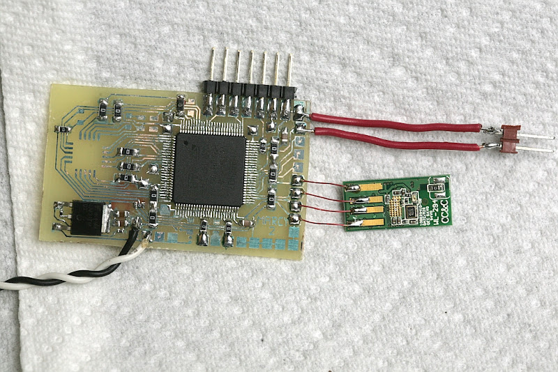
But I really don't know how to link wifi module through with USB. (My WiFi module is same with yours. Just different PCB outline, which is CC&C WL-294)).
Would you please give me some suggestion or give me some example code to try it?
I found many embedded system don't support MCU directly control USB WiFi module.
This problem has been bothering me for a long time, please help!!!
Simon
Hi Jack i use the MP32F4 with STM32F4 with standard 8 mhz crystal and all work fine at 168 mhz
Best
Roberto
"Should be noted the STM32 can be bricked if the PLL is misconfigured for over 168Mhz. JTAG will start timing out in the halt requests & you'll never be able to reflash it."
I think if you put the device in bootloader mode using BOOT0 and BOOT1 then you can get around this. This can also help if you disable the JTAG pins.