Dmitriy Ershov's Posts (7)

Sort by

Honda released the video featuring their new Civic Type R car in a mixed reality race of a professional car racer against a video gamer! The race between real-world Honda Civic R and Forza Motorsport 7 version was arranged by UNIT9, the production company. Reach RS RTK receiver was used to re-create the remarkably accurate behavior of a car.

3689732841?profile=original

Check the breathtaking film about this race (above)

Visit R vs R project page on the UNIT9 website to see project details.

Read more…

Hey everyone,

I want to share nice project I recently found on Youtube. It’s IR 3D Scanner Robot made by the group of students leaded by Nicolas Douard.  It turned out the project has amazing report containing step-by-step building guide, bill of materials, drawings, software and demos.


Here is the short overview:

The goal of the team was to perform 3D reconstruction using mobile embedded systems. The developed solution should be capable to generate the 3D model of indoor spaces.

The vehicle uses Actobotics standard platform. This base offers great traction and climbing ability (37°approach angle) and can easily handle heavy loads. Vehicle electronic components are mounted underneath the plate and includes the radios, Raspberry Pi + Navio 2, DC motors and its driver (drawings and 3d models are available in project's report).


A Raspberry Pi board is associated to a Navio 2 shield running ArduPilot for navigation Control. The Navio2 board is connected with Spektrum DSXM receiver and 433 MHz radio, moreover it generates a PWM signal for each motor. This signal goes to the motor controller via servo wires.


BKLvNCl3EidGs2poO0qC9jIYGkeZ_GgRKGgmQLrINX7idRdHEhHgpMsQu4sHaE2JLQokH972Fc_a9_ATzUWcq4T6mJJBDfqnyUxhJHpVKAfrQfq_sUSMS2LV9qqCPiNVqwPx_49B


The space above is left available for IR 3D scan system (Kinect 360). 3D reconstruction is resource expensive and requires a very powerful GPU/CPU combo. This makes it impossible to run 3D reconstruction on cheap embedded hardware like a Raspberry Pi

board. The data is therefore logged on the vehicle and later transferred to a remote computer that is to perform resource expensive 3D reconstruction (using Nvidia GTX 1080 GPU (8192 MB) and Intel Core i7 6800K CPU (6 cores, 3.40 GHz)).


CHJfIKrPcHacsklw_shhQY_qeN9g8MFkTrOG-PHYJI_i3fao7BHnJ06iqZKJ12LbqEtwlIU6U67iRXpM-VWoPoTfN7NjYM2Bfg04ZOfAVqQWA5REVz1lwpGVanVfbgaH5w6jNRYw


The IR 3D scan module’s primary goal is to log RGB and depth data which is to be used for 3D reconstruction. RGB-D frames capture is handled by Logger1 modified to run via SSH.

For processing ElasticFusion was used. It’s a real-time dense visual SLAM (Simultaneous Localization And Mapping) system capable of capturing comprehensive dense globally consistent surfel-based maps of room scale environments explored using an RGB-D camera.  The capture and the reconstruction processes can be separated thanks to dedicated loggers which collect raw data that is packed into a KLG file. This file can later be processed by ElasticFusion in order to generate a 3D model.

ElasticFusion exports MeshLab compatible data. MeshLab cleans and optimizes meshes and can export reconstructed 3D models to more common formats like STL or 3DS. An optimized model in this format can then be imported into 3D modeling software such as 3ds Max and manually modified to be, for example, suitable for 3D printing.


wrtaftAx5UbW-HN_KGTQ8mWeGIyTnctC9Qoe7JJAAqSGg4kn6oTHJcK3WVUn6KLjQhruy1a7GVHg_gi6RGxT8QVnewFs4QlSQQaqowlLUJ05M3whv8WhaXmAsKOEsHVcbsL-daxt

Electric kart reconstructed point cloud opened in MeshLab


6dKgkLIXjD9zCZ0SiybiFX7mV3Cl3UE9DZK-su7JjR4JAQbCY0AF7rmBZu94zvXQMLgWDSifTzGizbndkvXKf_8QxaohPAjSnEEBM_470EIwXtFIG77FMb4onjvGf_60CXQd23SS

ElasticFusion running with GUI


An extensive documentation of the Project and Embedded control system software may be found in the ScanBot 3D repository:


https://github.com/QBitor/ScanBot_ECS


Read more…

3689711640?profile=original

From Navio2 Project Shares:

This multi-rotor UAS will be used in search and rescue operations using object recognition to find a target and deliver a payload, e.g. to help an injured climber on traditionally inaccessible terrain needing to be dropped fluids, a torch, an insulating blanket and/or a flare to assist their survival and later rescue.

IMG_20170122_151419.jpg

A Mobius camera is connected to the Raspberry Pi with Navio2 attached, running an OpenCV application to detect objects. Their position in the frame is used to generate velocity data that is sent via DroneKit to ArduCopter, which then moves to center the drone above the object.

A full project description can be found at blog.mckeogh.tech23.

3689711595?profile=original

Read more…

RC Blimp Drone Autopilot

The autopilot on the blimp is enabled whenever the hardcore 80s music is playing

RC Blimp with Rapsberry Pi +Navio2 and autopilot algorithm written in Go: 

True Story Follows

A few years ago I worked on an autopilot module for a blimp and subsequently presented a PyCon talk about it. Like any developer looking back on previous works, I think the code was horrible and the talk could have been more substantive as well. The lime green Hawaii shirt, however, I have no regrets about. Sometimes I wear it to work and people tell me that they can’t hear what I’m saying with how loud my shirt is. It is true, I have even louder shirts that my wife got me for Christmas, including some wicked tie-dye and some absurd dye-sublimation designs.

Fast forward a few years, and everyone on the streets is clinging to Go as the hottest new programming language. So when I tried picking up Go, it was somewhat challenging because I had no practical reason to learn. My project at work will be stuck as a Python project until we undergo the deliberate and painstaking effort to re-write it in a compiled language. This effort to learn the language coincided with a desire to go back to the blimp project and revive the effort to bring it to a reasonable conclusion.

The Shortcomings of Last Project

The largest pitfall of my last endeavor to create an autopilot for the blimp was that it was not easily reproducible. I bought individual sensors and had to wire them up to a separate singleboard computer, and I had put together a laser cut acryllic design to house all the pieces. Then there was corresponding nylon screws and bolts to mount evertyhing. If I ever wanted to create a multitude of autopilot modules, this would become a painstaking and problematic effort for something that was a side project and a hobby. And obviously, the end goal is to deploy thousands of autonomous blimps to rule the skies, so an unscalable solution was not a solution at all.

The other project, while capable of basic flight, was not that great, which was amplified more after working on my current project. Calculating a compass heading, for example, relied on sterile conditions where the aircraft was completely level in the skies, which is obviously not a valid assumption. Otherwise, the basic ideas of flight were reasonable.

And finally, the last project lacked a reasonable user interface. I put some stuff together with OpenCV, but it was nothing that looked professional, and nothing to help diagnose any problem going on.

1df6ce44-dfc2-47b6-a9d5-3286d55a1a6c

The Go Re-Write

I re-wrote the entire autopilot algorithm in Go from Python for a few reasons.

My first concern was how to go about reading from sensors. This pretty much required C++ usage, so I could either write everything in C++ or just use a language that was easily compatible. Go is advertised as a language that can do this, and the final implementation proved that this was relatively straightforward.

Another concern which was later validated is that the autopilot would be a multi-threaded environment. I didn’t want some sort of whacky scenario where the serial port blocked for a prolonged period for whatever reason and subsequently prevented the autopilot from controlling the aircraft. The only scenario in which some sort of crash would be desirable is if Kraft foods hired me to paint a 30 foot blimp like the Kool-Aid guy and have the blimp ram full speed into and through a brittle wall. Go is a reasonable language choice for an application with multiple concurrent processing tasks, and while it’s fairly obvious that motor control, computing waypoints, reading from sensors, and reading from user input could significantly benefit from executing independent of each other, it turned out that my autopilot implementation was inherently asynchronous in virtually all aspects, and combined with the long lived nature of the program, Go proved to be an excellent choice.

The last reason to use Go was for the simple matter mentioned above that I need to learn Go, in part because I want to, and in part because it’s being used frequently at work so I should at a minimum be able to intelligently understand Go code and ideally be able to write my next project using it.

And finally, another point in Go’s favor was that it would be faster and use less resources. I’m not necessarily concerned with either, but faster code is always good and in this case may be able to enable better navigating with higher frequency computation. Additionally, if I can use less compute resources, I can use less battery and therefore prolong flight time.

59e69ef7-e2ea-4238-9565-7407b7a3ed78

Requirements and Features

In its current state, the blimp is not yet 100% complete, but the bullets enumerated below represent either a completed feature, an implemented but untested feature, or a feature with a small enough scope that it’s safe for me to promise its completion.

  • A client laptop is assumed to work in conjunction with the autopilot.
  • Blimp will take off vertically and hover until waypoints are specified
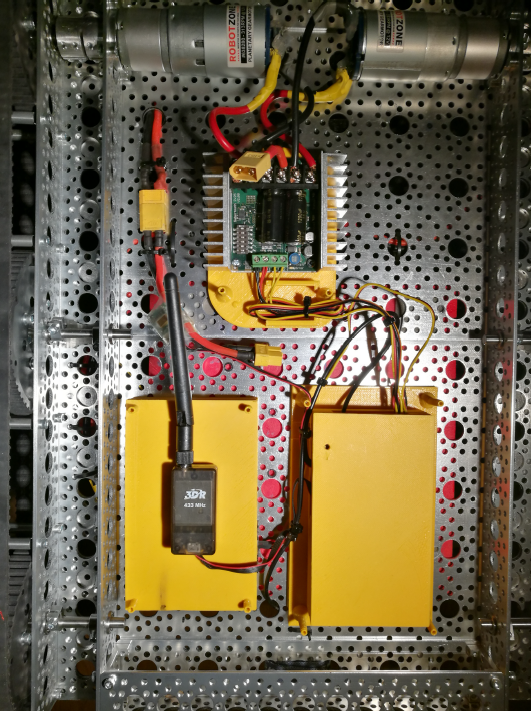
  • Communication range between laptop and blimp is a function of the XBee modules used (the ones I’m using can work about a mile away if there’s line of sight communication)
  • Feedback from the blimp, such as target heading and output sent to the aircraft’s servos and motors, is passed back to the client; this proved invaluable for testing and diagnosing problems.
  • Waypoints are specified in real-time by clicking on a map on the user interface (it’s assumed the client laptop has internets)
  • Waypoints can either be consumed as the aircraft reaches them or the aircraft can simply loop through all waypoints continuously
  • In the event of lost communication, the blimp will immediately shut off its motors and pitch downward
  • The compass needs to be re-calibrated whenever the geographic region changes; we can’t all live in the Bay Area. Calibration starts and stops with the press of a button on the user interface, and the autopilot module just needs to be rotated in all directions until a reasonable heading is established.
  • When not actively flying, the user interface has buttons to individually test pitch, yaw, thrust intensity, and the thrust vector
  • PWM min and max ranges (which can vary by servo or electronic speed controller or can have different ranges based on aircraft nuances) can be adjusted on the client side
  • Blimp will cruise at 5 miles per hour to minimize power consumption; blimp will slow as it approaches a waypoint.
  • Blimp will fly 25 meters above ground level

a1023e35-ed8c-4070-9d1d-34061b199060

Major Parts List

bc28c086-6d2e-4e93-8a39-c4da34c0bd19

Mistakes in Current Implementation

It is true. Even The Lobbdawg makes mistakes. From the initial flight test, there were a few noticeable problems.

Forward speed is embarrassingly miscalculated depending on the quadrant the azimuth of the blimp lands in. This caused speed to be represented as a negative value, which then caused the blimp to compensate and try to increase speed. And now, the blimp would fly too fast, like the gazelle.

The algorithm for hovering was based entirely off of incorrect assumptions. The idea was that if the pitch of the blimp is 0 and I can keep the pitch of the blimp at 0, then I must be hovering. This assumption is incorrect, but it’s also very difficult to take off in a hover based on this sort of flight strategy.

The determining factors for thrust intensity are also currently incorrect. The idea was that the thrust vector for the motors should always be at a neutral (roughly 45 degree) angle, and altitude would be controlled by the tail elevator. Therefore, while the motors would still provide upward thrust, I only adjusted the thrust intensity based on the current forward speed of the aircraft. This created the problem that if the blimp was flying too fast, the motors would shut off, and the blimp would slowly descend in altitude while the tail elevator and rudder couldn’t direct the aircraft as well with the reduction in power.

Finally, in some cases during flight, control of the motors was completely lost if a preceding operation kept the motors powered down. While I’m still speculating somewhat here, my guess is that the PWM update frequency should happen at 50 hertz. Currently, the update frequency is directly correlated to sensor read frequency.

e6d8adbf-7aa5-46cb-8f91-5e7ce82f0541

What Went Well

While the test flight to me felt like a failure, it certainly wasn’t because I learned enough to know how to correct the problems. On top of that, it was easy to take for granted some of the now proven assumptions. Primarily, the math used to calculate output to the tail elevator and rudder proved to be spot on. The blimp was able to fly directly to waypoints and cut directly through the target. If the blimps can be considered arrows, then you could consider me to be Robin Hood, but only in the sense that I can shoot arrows really well. Not in the sense that I’d steal money because I don’t want to go to jail. Also I think Robin Hood dies in the end.

But I digress. The point is, pitching and yawing is based on the idea that we have a curent angle (in either the pitch or the yaw plane) and a target angle. From there, we have a target angular velocity. Based on the current angular velocity, we can then output a corresponding intensity percent to the motors. As a result, we can safely compensate for things like wind, and we can counter intuitively pitch or yaw in the opposite direction of the intended target if the aircraft is spinning too fast.

Another point to put on the scoreboard is the effort in putting together all of the details in the user interface proved incredibly fruitful. While some of the view data was based on an idea of putting something cool looking on the display, it ended up helping to diagnose and reveal the problems mentioned above. Had it not been for the user interface, I would only be speculating and postulating what the problems were.

eab881e9-141b-4103-96d2-bdb478e702bd

What’s Next

Put simply, I’m going to fix the problems listed above. They’re all fairly straightforward to address except the problem around thrust vector angle and thrust intensity.

After thinking it over, I’d like to rework the flight algorithm differently. Blimps are notoriously a combination of flying a helicopter and flying an airplane (you could think of these RC blimps as a crossover between an MH-53 Pavelow and an F-14 Tomcat, the performance characters are comparable), so it ends up making sense to simply decouple those respective components and let them operate entirely independently. In practice, they’ll be coupled together by happenstance and equilibrate to an ideal flight configuration. The current algorithm for controlling altitude is based purely off of pitching the aircraft up or down through the tail elevator. This is fine; now, the motors should operate independent of the elevator to help manage altitude and forward speed.

The thrust vector will be computed first. I know I can already ascertain a target upward velocity to reach a target altitude, and I can already ascertain a target forward velocity to reach a target forward speed. Throw some arc tangents into the mix, and now I can get the ideal thrust vector to apply forward and upward forces in the correct proportions. Now I can just offset the resultant angle with the current pitch of the aircraft to apply forces in the perfectly correct directions.

Finally, thrust intensity can be computed in a similar way; get the required forces to apply in the forward and upward directions, and the final force applied will be the square root of the sum of squares.

This sort of approach I think will end up creating a very elegant flight pattern. Target speed can also take altitude into account, where target speed will be a function of the current implementation of target speed interpolated against the current altitude relative to the target altitude. In plain English, the blimp’s target forward speed will increase from 0 to max as it ascends, which will end up causing the blimp to rise vertically and then gradually speed up as it reaches a safe altitude.

In normal flight where the blimp is flying straight forward to a target destination, the thrust vector will have reached perfect equilibrium with maximal efficiency to distribute upward and forward forces (in practice this means that the thrust vector will be at or near parallel with the blimp’s air frame).

f4297eac-43b3-463f-9dda-4ba7977c6b42

Author's blog

Read more…

3689705457?profile=original

I've just seen cool tests from Jeff Taylor and his Event 38. They integrated Emlid's Reach in E384/E386 mapping drones and verified processed data accuracy using data from Trimble R6 Model4. 

With the Emlid Reach RTK GPS Receivers now available, we’ve been conducting tests to determine their accuracy and working on the integration into the E384 and E386. The goal was to determine relative, or scale, accuracy as well as absolute accuracy verified with a survey grade Trimble R6 Model 4.

We post-processed the data in three different ways to explore the effect each would have on the resulting data. For PPK GPS processing, there is a receiver onboard the aircraft and another stationary receiver on the ground. The ground receiver (base station) is used to calculate corrections to refine the position of the airborne receiver. The base station also calculates a precise GPS coordinate for itself, with the option of writing in another, more accurate coordinate if desired. We constructed orthomosaics on the Drone Data Management System™ using geotags calculated from the Reach base station and the Trimble base station, using either the Reach base coordinate or the Trimble base coordinate. The combinations for each test are listed below.

Base Station CorrectionsBase Station Coordinate
ReachReach + CORS
ReachTrimble R6-4 + ODOT VRS
Trimble R6-4Trimble R6-4 + ODOT VRS

Test1:

It was clear straight away that there was an offset between the Reach and Trimble coordinates, so we focused on scale accuracy for this test. The offset is clearly visible in the image below, where emp is the Reach base station coordinate and 6 is the same coordinate shot by the Trimble R6. To measure the scale accuracy of the Reach-only orthomosaic, we measured distances between several pairs of GCPs in different directions. The error was 3cm in each case.

GCP PairReach Orthomosaic (m)Trimble R6-4 (m)
12-4171.87171.84NE-SW
19-3115.23115.20North-South
5-2145.46145.43East-West

emlidmisalignment

Test2:

Processing the geotags using the Emlid Reach base station but using a coordinate shot by the Trimble R6-4 resulted in very good accuracy relative to the Trimble shot GCPs, with an RMSE of 3.36cm.

GCPError (cm)
22.631
33.749
44.799
52.072
72.867

test6

Test3:

Finally, processing using the trimble base station for both corrections and the base coordinate yielded similar results to those obtained with the Reach corrections, RMSE 3.54cm.

GCPError (cm)
24.667
33.099
44.189
52.104
73.075

test5

These results should be considered very preliminary, as there were a number of factors that could have adversely affected the accuracy. The Reach coordinate may improve once we are able to calculate it with a closer VRS. The mission was collected with a relatively high GSD of 3.5cm/pixel, so it is difficult to pick the GCPs accurately.

Still, there are some conclusions we can draw from this data. Even without a good base station coordinate, the Reach system can produce very good scale accurate results. When paired with a higher quality coordinate, the Reach can produce very good absolute GCP coordinates. If a fixed position can be marked once by a survey grade GPS, then it can be used as a reference point for all missions in the same area, forever. It may also still be possible to obtain similar results with the Reach alone using the VRS network or Precise Point Positioning.

We’ll run more tests to verify the accuracy, but initial results are very good. We’re now making the first deliveries of the Reach system to select clients before a wider release in the very near future.

Article source

Read more…

      Direct Line reveals their open source service - drones with Pixhawk and Reach RTK inside equipped with high-powered on-board lights:

3689704881?profile=original

While the vast majority of drone projects seem focused on photography, video surveillance or acts of war – Direct Line insurance has been investing in new ways to use unmanned aerial vehicles to help preserve life in novel ways. KitGuru was invited to experience the Fleetlights project at Wrotham Park and to see, first hand, some of the innovative ideas that this open source project is developing.

Now presenting motor sports on the BT Sports channels, Suzi Perry will be familiar to KitGuru readers from the 8 years she spent presenting Gadget Show. Alongside the technical presentations, Suzi asked us to imagine travelling alone on a train at night to a station that’s far away from a town centre. It’s cold, dark and you don’t feel safe. How cool would it be if you could press an app on your phone and have a drone waiting for you when you get off the train?  The drone would follow you to your final destination, illuminating the way with powerful Fiilex AL250 spot lights, only leaving when you say that you are “Safe inside”.

In a more dramatic set of circumstances, imagine you were trapped somewhere but you knew that pressing a button on your phone would place a drone right above your position – with a light to direct rescue services. How useful might that be?

Seeing Fleetlights is much easier than explaining the technology in words, so we’ve created this video for you to watch via VIMEO (Below) or over on YouTube HERE.

Mark Evans is the marketing director for Direct Line and is the driving force for a series of technology initiatives that his company will be funding.

“Traditionally, we have been a ‘fixer’ company”, Mark told us. “We’re there after a customer has experienced a problem and it’s our job to help them recover. We wanted to kick off a series of new projects that use some of the latest technologies and then mash them together with the help of experts, to see if we can improve prevention – to help protect people from problems before they even happen”.

Next, we wanted to dive a little deeper into the technology itself. For that, we spoke with Simon Cam who calls himself a Technical Creative Partner. He originally studied design and art direction at university, but these days he’s focused on Python and Javascript across the full stack from front-end to back-end to server admin.

3689704968?profile=original

3689704943?profile=original

3689704899?profile=original

Simon explained that there were two key challenges for the Fleetlights project. First, increasing the accuracy of the GPS system and second to augment the available mapping/tracking software in the market – in order to create something very fast and responsive, that also allowed a group of drones to work as a team, using a mesh network that can be daisychained.

The demonstrations that KitGuru took part in involved a smartphone with advanced GPS ‘bunny ears’ attached. This attachment means that Fleetlights can operate to an accuracy of a few centimetres – rather than the 1-8 metres that most of today’s systems use. The system we used included RTK Reach units, but Simon was confident that this new generation of GPS accuracy will be normal in mobile phones very soon.

Fleetlights drones have advanced open source mapping technologies already built in, but they use them in a unique way. Routes are predicted in advance and the Fleetlights drone will actively lead you to your destination – so the intention is that you follow the lights. You can veer off the predicted path by up to 20 metres, but at a certain point the drone starts to ‘wonder’ if you’ve given the correct destination.

“We have successfully tracked a car at close to 50 miles per hour”, said Simon. “But there are a lot more improvements to come – including advanced collision detection and blue cell hydrogen power units – while at the same time we’ll need to work closely with any Civil Aviation Authority legislation that comes to pass for commercial drone projects”.

How the project will work commercially and which organisations will pick up on it first, is still to be decided. Mark explained, “We want to encourage the exploration of these new technologies – especially among students. There is no specific commercial goal in mind, we just want to encourage innovation in technologies that can help accident prevention”.

You can find out more about Fleetlights by visiting the site and downloading the technical manual here.

KitGuru says: At the start of the evening’s demonstrations, we were totally fixed on the commercial difficulties that would make it hard to deploy Fleetlights across the country. By the end, it became clearer that this kind of funding for a wide range of innovative projects is genius and very encouraging. As the software/tracking become more robust, the cost per unit drops and adoption of these technologies becomes more widespread – we could well reach a point where Fleetlights (and related projects) are dead easy to implement. For now, the idea is fascinating and we applaud the investment.

Video from Direct Line channel on Youtube:

Fleetlights technical manual is here.

Article original source.

Read more…

Recently I've stumbled upon a very nice master's project on vice.com:

It looks cooler than Google’s self-driving panda car, even if it’s only miniature. This model bike is a step toward fully autonomous motorcycles and overcomes a main challenge with two-wheeled vehicles: not falling over.

Eric Unnervik, a master’s student at the École Polytechnique Fédérale de Lausanne (EPFL) in Switzerland, developed the mini bike to demonstrate some of the technology that could lead to full-on autonomous motorbikes. At the moment, the bike needs a human controller to tell it where to go via a remote control as it has no GPS, but it can ride there by itself—crucially, without flopping on its side.

In a video, Unnervik explains (in French) that his grown-up Hot Wheels toy contains a Raspberry Pi computer with NAVIO2 autopilot and sensors that measure the bike’s angle and speed. A servomotor adjusts the steering angle as needed so the bike won’t fall as it travels up to 60 km/h.

He says he’d ultimately like to race a 100 percent autonomous bike against one with a rider.

Cars have so far stolen the autonomous road vehicle limelight, though Yamaha unveiled a motorbike-riding robot at CES this year, and Google has lobbied to keep regulations open to testing autonomous motorcycles.

The question remains as to quite why anyone would want a motorbike that drives itself—to get that wind-in-your-hair feeling without the hard work, perhaps?

Photo from the Recantha:

The Mini Bike

© 2016 EPFL / Alain Herzog

Original source with action video

Read more…