ardupilot (7)
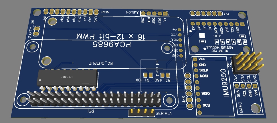
This board is one of many Linux-Based boards that run Ardupilot. What is spepcial about this board is that has very simple architecture. Only necessary components has been added. No extra or redundant components. However it is still expandable and more sensors can be added if you want to.
The PCB shield is designed to use simple breakouts available in the market. No special soldering skills or components are required. You can build from scratch your own board using this PCB and learn the basic architrecture of Ardupilot boards and move to next step where you add extra sensors and ending by building your own board.
Yes this board acts more like a developing kit rather than a ready-to-fly board. Again if you want to fly with it you can but then do not use pin headers and solder the breakouts directly on the board.
On the software side. OBAL board does not have special drivers. All you need to do is to clone ardupilot repository and compile the code. Nothing special, nohting hidden , completely open source.
For more information please check Ardupilot Documentation. Also there are some videos that describe in details how to build it, compile and deploy the software. Have fun :)
This video illustrates the adaptation of a ArduPilot Rover to the Artificial Intelligence DonkeyCar environment. This includes the adding-editing of 5 files of the DonkeyCar library. A linear AI model trained by behavioral cloning resulted in a satisfactory autonomous test drive.
These instructions explain how to set up a Spektrum DX7 transmitter for 6 different flight modes, using just the 3 position Flaps switch (in combination with the Rudder switch). This way you'll use just one channel for the flight modes and leave the Gear and Aux2 channel open ...
(note that you have to use the DX7 in "airplane mode", not in "heli mode" to fly a quadcopter)
- switch on your remote while pressing SCROLL DOWN and SELECT
- go to "D/R Switch Sel" menu (with the SCROLL UP/DOWN button)
- select "Com Rudd" by pressing the INCREASE button
- go to the "Input Select" menu (with the SCROLL UP/DOWN button)
- press select until you reach "Flap:", make sure it is set to "System" (you can change the setting with the INCREASE button)
- press SELECT
- set "Flap Trim" to "Inh" by pressing the INCREASE button
- switch off the remote
- switch on the remot
- Press SCROLL DOWN + SELECT to access the programming mode
- Go to "Mix1" (with the SCROLL UP/DOWN button)
- go into the menu of "Mix1" by pressing the INCREASE button
- Select "Flap" > by pressing the INCREASE button
- press SELECT to jump to the second position and select > "Flap" by pressing the INCREASE button
- press SELECT
- Set rate to "+100%" and "-50%" (with the INCREASE/DECREASE button, you'll have to put the FLAP switch in the "N" position for the first value and into the "2" position to set the second value)
- press SELECT
- Set SW to "Mix" by pressing the INCREASE button
- press SELECT
- set offset to "10" by pressing the INCREASE button
- Go to "Flap Sys" menu (with the SCROLL UP/DOWN button)
- set Flap Norm = UP to "46%" (with the SCROLL UP/DOWN button)
- press twice SELECT
- set Flap Mid = DN to "8%" (with the SCROLL UP/DOWN button)
- press twice SELECT
- set Flap Land = DN to "100%" (with the SCROLL UP/DOWN button)
- press twice SELECT
- set Auto Land to Inhibit (with the SCROLL UP/DOWN button)
connect now your APM to the Ardupilot Mega Planner, go to the setup page and assign different flight modes to the switch combinations of your remote.
I like to have easy access to the simple mode (just to get very quick out of a difficult situation) which is the reason why I have two switch combinations programmed for simple mode. I have set it the way that simple mode is always selected if the "Flaps" switch is on "N" (away from me), no matter if the "Rudder" switch is on or off. This way I have just 5 modes accessible, but I can very easy and quick switch back to simple mode.
(this is based on the blog post by Limebear)
www.diesunddas.co.uk
This is how it worked for my DX7,
I use various switch combinations of the FLAPS and the GEAR switch which will give you 6 modes;
(note that you have to use the DX7 in "airplane mode", not in "heli mode" to fly a quadcopter)
- Press SCROLL DOWN + SELECT to access the programming mode
- Go to the "Travel Adjust" menu with the SCROLL UP/DOWN button
- click the SELECT button till you reach "Flap", then set "Flap" to "U 65%" and "D 65%" (INCREASE/DECREASE button, you'll have to move the "Flap" switch to select between "U" and "D", this means put the switch in "N" position (away from you) to program the "U" value and move the switch to the "2" position for the "D" value)
- Leave "Gear" on 100% - 100%
- Go to "Mix1" (with the SCROLL UP/DOWN button)
- go into the menu of "Mix1" by pressing the INCREASE button
- Select "Ger" > by pressing the INCREASE button
- press SELECT to jump to the second position and elect > "Flap" on by pressing the INCREASE button
- press SELECT
- Set rate to "19%" and "31%" (with the INCREASE/DECREASE button, you'll have to put the GEAR switch in the "0" position for the first value and into the "1" position to set the second value)
- press SELECT
- Set SW to "on" by pressing the INCREASE button
- Leave Offset at "0"
connect now your APM to the Ardupilot Mega Planner, go to the setup page and assign different flight modes to the switch combinations of your remote.
I like to have easy access to the simple mode (just to get very quick out of a difficult situation) which is the reason why I have two switch combinations programmed for simple mode. I have set it the way that simple mode is selected if the "Flaps" switch is on "N" (away from me), no matter if the "Gear" switch is on or off. This way I have just 5 modes accessible, but I can very easy and quick switch back to simple mode.
(this is based on the blog post by Nick Wadman, I just adopted the programming description for a DX7)
www.diesunddas.co.uk
27th June 2010 - 3D Telemetry using Google Earth - Just like a sim but for real!
Due for release shortly includes: Adding your own google sketch up models, equipment/models database, maxpilot,mega, kml, logging, sharing of config and kml/model information
Next job prior to release to make a HUD/OSD instead of the solid instruments displayed below.
Currently I am adding support for a serial camera. The serial camera is a simpler device than real video but works quite well. The Kml output will also include an option to show images for any part of the journey
release later in year to include two way telemetry.
the existing functionality mentioned below will remain valid, using google earth sim is optional
Project renamed to "ArduFab" (Beta)
15th June 2010 - FAB 1.2 Flight Computer Version 1
14th June Update - here
Please do not use for actual flight. This is beta and not fully working or tested!
For all those who tried the earlier version .. "I've refreshed the msi it wasn't setup correctly sorry"
Thanks to so many contributors for putting their projects on the web. I've used many people code!
What is working
Entering a com port, setting a baud and clicking the "ON" button will read ardupilot telemetry
The instruments that appear when you switch “on” will show values
The Log will show you raw data from the ArduPilot.
The log will can also show Attitude and Position
The H marker on the map shows where the ardupilot currently is (In progress!)
(There is a large delay before the map shows the correct information. To be fixed)
If the telemetry is switched on before the ArduPilot is started then the map shows the waypoints
Only web links work in the tree
The summary is very basic at the moment and only applies if a full start up has been
What isn’t working
Quite a bit!
The radio window only shows throttle, might show battery but not tested
The radio window can’t be resized correctly
The map shows your waypoints but needs much more work
Access to configuration tool and code editor
Saving of journeys
Saving of configurations
Direct IMU telemetry is implemented but held back for testing
Waypoints checkbox on the log
All menu items and tool bar buttons
Map reset
Zero altitude
Two way com
Diagnostics and additional instrument controls
Flight Computer
Set home via map
Clear map / reset map
Adding properties such as ardupilot source path
Video
Additional sets of indicators + night/day mode effects
Replay journey
Lots of config options
Visible and audible alarms
History______________________________
This was the original project that I found on the internet that got me thinking about a windows ground station.
The brilliant ArduPilot ground station prompted me to look for a solution because it is difficult for me to have labview installed on my machine. Doesn't comply with our software audit and besides that I am not happy about the price of labview.
I like arduino and the microsoft micro framework, the two products seem to have their places in this world. As such I decided to see if the Micro framework could provide a 3/5 volt mini ground station.
My project has developed since I found these controls but I include a link because the maths in this project makes creating scalable/resizable moving controls very simple.
http://www.codeproject.com/KB/miscctrl/Avionic_Instruments.aspx
GroundStationT
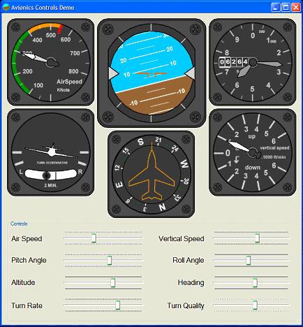
My ground station project is now working with text based imu output or with the ardupilot. The instrument controls are now single widget windows that can be re-positioned and resized independantly.
The main control is the attitude indicator control. When it is moved all other control move with it. The mouse wheel is used to increase/decrease the size of an instrument.
The application has a main frame but the instrument controls are displayed outside of the main frame. Yhis allows the frame to be minimized and the instruments to occupy the entire screen.
The view menu currently has a google map showing current position and next waypoint, current work is to enable the map to be displayed in place of the ground (below the sky) in the attitude indicator and to allow more transparency of other instruments.
The google map link is going to be interesting to develop alonside a Telit GSm module that I have. By the google code initially came from the ArduPilot config tool, so hats off to the clever ground station pair!
I initially coded the processing of serial telemetry and the instrument controls using the micro frame and a tahoe II board. This proved the project would work and once the various instrument controls are working with proven tested values, I indend to convert the project back to the micro framework.
The current windows project can be found here but it is untested in the field and should not be used for actual flight monitoring. The current project is just a .exe, it requires microsoft windows framework 3.5 and will fail to run if you don't have it installed.
FYI: Current cores (board support) provided by MF4 are as follows but you can also build your own using the free porting kit!
ARM v4,
· ARM Thumb
· Thumb-2
· Blackfin
Development Boards
The porting kit provides sample ports available for the development boards listed below. These sample ports include the source code.
- Atmel SAM9261-EK development board (ARM core AT91SAM9261)
- Atmel SAM9RL64-EK development board (ARM core AT91SAMRL64)
- Atmel SAM7X-EK development board (ARM core AT91SAM7X512)
- Phytec phyCORE-ARM7/LPC2294 (Rapid Development Kit PCM023, ARM core LPC2294 by NXP)
- Embedded Artists EA-LPC2478 development board (ARM LPC2478 by NXP)
- Crossbow MOTE2 platform from Crossbow (for Marvell PXA271 processor)
- Freescale i.MXS development kit (Freescale MC9328MXS)board for i.MXS processor
Memory Requirements
The memory requirements for the .NET Micro Framework depend entirely on which features you use. In its smallest form, the framework requires 64 Kb of RAM and 256 Kb of flash memory.
