Thorsten's Posts (8)

Sort by
T3

Announcing Mavis

3689681510?profile=original

We are happy to announce Mavis - a new UAV photogrammetry and mapping software.

Mavis is specifically designed for agricultural, archeological and mining surveys.

Mavis covers the entire workflow from single UAV images to GIS ready maps. It comprises precise georeferencing, on-site image analysis and stitching, image preprocessing, the generation of digital surface models and orthophotos, color post-processing, the computation of vegetation indices, as well as the generation HTML reports including WebGL 3D models.

Mavis is designed with an intuitive workflow in mind - from georeferencing to 3D mapping and the generation reports - while providing state-of-the-art algorithms.

Detailed information is available at mavis.bitmapping.de

Preprocessing

  • Precise georeferencing is realized by a combination of Pixhawk/APM dataflash log file analysis and a specific CHDK script for Canon cameras. This combination allows accounting for shutter delays with high precision.
  • For other cameras the camera trigger information recorded in the log file can be used for georeferencing. Images which have already been geotagged can be used as well.

3D Mapping

  • Orthomosaics and Digital Surface Models form UAV imagery are generated using MicMac. MicMac uses a multi-scale, multi-resolution approach for dense matching and sophisticated camera calibration models.

Color Manipulation

  • Orthomosaics often require further processing for scientific analysis or interpretation purposes. Therefore, Mavis provides various tools to enhance and manipulate colors such as white balance, gamma correction and decorrelation stretching amongst others. Spatial filters to remove noise are implemented as well.

Vegetation Indices

  • Various vegetation indices can be derived using Mavis.
  • For single camera setups the filter type can be selected. Blue and red filters are supported.

Reports

  • HTML reports can be generated following 3D Mapping. A 3D WebGL model is generated and linked to the report.

Availability

  • Mavis is distributed free of charge with our UAVs.
  • It is currently in the final beta testing stage for regular distribution.
  • Please contact us for availability.

Mavis is made to evolve! Please share your thoughts, requirements and suggestions regarding Mavis and UAV mapping workflows in general.

Best regards,

Thorsten

Read more…
T3

GPS positional accuracy III

3689678308?profile=original

Hi all,

this is a short follow-up on my previous tests (I, II) with u-blox different u-blox M8 GPS modules.
This time I'll report about a survey campaign of several days with different copters and GPS. After processing the data I was surprised about the positional accuracy so I decided to share some numbers.

We used two copters running AC 3.3. One with an M8N and the other with an M8T GPS. The survey was conducted over a period of 4 days.

Six orthomosaics were overlapping:

Dataset   Day time
A         3   10:40
B         1   11:20
C         4   12:00
D         4   10:20
E         4   11:00
F         1   10:00

The orthomosaics were generated using direct georeferencing, i.e. without any RTK processing or ground control points. Hence, the final accuracy, or to be more precise the spatial offset between the maps, is a function of the accuracy of a single GPS and the image processing pipeline.

Since the flights were conducted over 4 days with different GPS and copter setups, the positional offset shows the overall GPS accuracy that can be achieved with M8 GPSs. The processing chain was the same for all datasets. However, there is for sure some influence as well. [I'll provide more details about image processing in my next blog post.]

Flight altitude was 50-60 m. Images were taken using a Canon S110. The size of the survey locations ranges form 5 to 25 ha (12-60 acre). The length of the entire area covered by the orthomosaics (from A to F) is 2.7 km (1.7 miles).

The maximum spatial offset between the orthomosaics is 1.2 m (3.9 ft). The average is 0.87 m (2.9 ft).

Overlay   Offset
A vs B    0.8 m / 2.6 ft
A vs C    0.6 m / 2.0 ft
B vs C    1.2 m / 3.9 ft
B vs D    0.4 m / 1.3 ft
D vs E    1.1 m / 3.6 ft
E vs F    1.1 m / 3.6 ft

Based on my previous tests I expected a much lower accuracy of about 2-4m maximum spatial offset. But it seems that both, the M8 GPS as well as the image processing pipeline, are pretty accurate and stable.

My next tests will be on RTK post-processing as well as the (promised) bench comparison between different M8 versions and antennas.

Best regards,
Thorsten

Read more…
T3

Google’s Cyber Drone Crashed

1200x-1.jpg

From Bloomberg:

The unmanned Solara 50 fell to the ground shortly after takeoff on May 1 and the U.S. National Transportation Safety Board is investigating, Keith Holloway, an agency spokesman, said in an interview. The accident occurred at a private airstrip east of Albuquerque and no one was injured, he said.
The crash is a setback for Google’s high-altitude vision of how to bring Internet access to areas of the world without sufficient infrastructure on the ground. Titan Aerospace, the company Google bought last year for undisclosed terms, built the drone, which its promotional material says has a wingspan of 50 meters (164 feet). It is supposed to fly above the weather, where it could then beam Internet signals to earth as if it was a satellite.

Read more…
T3

3689649924?profile=original

Hi all,

following my last post on positional accuracy, the discussion about ground planes and shielding as well as the general debate about the M8N, I started a series of tests comparing different M8N modules. This is the first part where I focus on comparing the modules in a bench test to compare positional accuracy.


The setup

I tested the following boards with settings optimized for Ardupilot:

Additionally, I tested the DroTek / M8N / T0027 with an "external" 9cm ground plane.

Since all modules produce low HDOP/PDOP values - around 0.7 and 1.3 respectively - the comparison focusses on positional accuracy/stability. Therefore, all GPS boards were plugged in for 10min before recording. Then I recorded their positions for 10-15min using u-center. Scatter plots of the position errors are used to compare the boards.
As a reference I recorded the GSG EMI in parallel when testing the others.
The image above shows the setup on the roof and the image below a closeup of test rig.

3689650050?profile=original

DroTek with the additional ground plane:

3689649938?profile=original

XY scatter:

3689649981?profile=original

3689650109?profile=original

Results

  • It is obvious that the CSG EMI and the DroTek with external ground plane outperform all other boards. 
  • The DroTek and the VR show comparable accuracy.
  • The CSG XL shows better performance compared to the DroTek and the VR but is not as good as the CSG EMI and the DroTek with external ground.
  • The 3DR 6H shows a much more scattered distribution.

Discussion

  • The board design (electronics) does not seem to have any influence.
  • Larger patch antennas result in higher accuracies.
  • A larger ground plane results in higher accuracies.
  • The ground plane seems to have a higher influence compared to the antenna.

u-blox provides a diagram (page 19) showing the effect of the size of the ground plane for patch antennas. Unfortunately, the ublox document only lists 18mm and 25mm antennas. For 25mm antennas 7cm for the ground plane seem to be sufficient. For the 35mm it should be larger. 

Remark
The results presented are only from one test. So there is for sure uncertainty. However, I made similar test the past days with comparable results. The 3DR 6H performed better in previous tests but not as good as the M8Ns, which performed not as good as in the results presented above (except the CSG EMI which showed similar results - I have not tested the DroTek with additional plane in previous test).


The next step is to compare the CSG EMI, the DroTek with and without the additional ground plane and the 3DR on a copter to compare the influence of the ground plane as well as of the shielding.

Cheers,
Thorsten

Read more…
T3

3689643216?profile=original

GeoUAV is a specialized Workshop in the frame of the ISPRS Geospatial Week 2015. Dedicated to Unmanned Aerial Vehicles (UAV), it will bring the opportunity to research scientists and practitioners to share their experience in development and application of UAV for geospatial data acquisition.

3689643225?profile=original

The aim of the GeoUAV Workshop is to present advancements in the field of UAV geospatial data acquisition for civil usages. Themes and topics will include general purpose technological and data processing developments as well as application domains such as agriculture, environment, civil engineering, archeology, etc.

Call for Abstracts

Deadline for the submission of abstracts for oral or poster presentations is 15 April 2015. Authors will be informed of acceptance by 1st June 2015. Submission details and guidelines for authors can be found in the Abstract Submission section.

Topics

Submissions are invited in, but not limited to, the following areas:

  • General purpose developments
  • Flight programming and navigation
  • Active and passive sensors
  • Data georeferencing
  • Ortho mosaicking
  • Digital Surface modelling
  • Radiometric calibration and correction
  • Data processing

Others...

  • Applications
  • Agriculture
  • Environment
  • Civil Engineering
  • Architecture & Archeology
  • Water and coast survey
  • Unusual applications...

Looking forward to seeing you at GeoUAV 2015!

Thorsten

Read more…
T3

Some tests on GPS, geotagging and stitching accuracy

Hi all,

I want to share some results of comparisons between different GPS modules as well as different approaches for geotagging and stitching images based on APM:Copter log files.

3689631231?profile=original

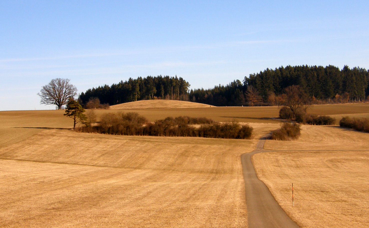
CAM_TRIGG_DIST (blue) vs. adjusted coordinates (green). Stitching is based on corrected coordinates.


The background is that we were aiming for a tool, which would allows us to check the image and geotagging quality immediately after completing a survey mission. So, in case of any camera triggering or geotagging errors (as well as image quality problems) one can repeat the mission again with different settings without having to wait for any complex and time consuming processing in the office. Additionally, I was interested in the positional accuracies one could expect from repeated survey missions and with different GPS modules. Hence, this post focuses on different aspects of positional accuracy. It provides a short summary of our experiments. It is not a scientific study and most of the tests were not repeated. So this is just intended to be a rough guide. Anyway, I hope it will be helpful to some of you.

1)        A comparison of the PDOP (Dilution of Precision) values between different common GPS modules for the Pixhawk autopilot

The crucial component for geotagging images as well as for geo-referencing in general is the GPS receiver. There are mainly 2 different u-blox systems currently in use together with the Pixhawk: the LEA 6H  and the NEO M8N.

For a test I mounted the following three GPS on my copter:

3689631252?profile=originalTest setup: 3DR LEA 6H, VR M8N and CSG M8N

The major difference between the two M8 modules is that the CSG M8 has a larger antenna (there is a „mini“ version with a smaller antenna available as well) whereas the VR M8 has an additional amplifier. VR M8 was connected to the Pixhawk as GPS1 and the 3DR 6H as GPS2. The CSG M8 was connected to my Laptop via USB directly. I used Mission Planner to monitor the VR and 3DR GPS modules and u-center to monitor the CSG one. Because AC3.2 is reporting is the PDOP and not the HDOP, we need to compare the AC3.2 HDOP with the PDOP reported in u-center. It is also important to set the "Min SV elevation" to the same values. To compare the performance I tested all three modules in parallel. In a first test I compared the performance outdoor and indoor (close to a window).

Results of the outdoor test

  • The LEA 6H always shows less satellites and a higher PDOP compared to the other two (~1.7 vs. 1.1)
  • The VR M8 is comparable to CSG M8 when the "Min SV elevation" of the latter is set 5deg. If "Min SV elevation“ of the CSG is set to 10deg the VR is slightly better. This is why I assume that "Min SV elevation" is set to 5deg on the VR M8.
  • The CSG M8 was the first that got a 3D Fix and it was better for quite a while. Interestingly, the position accuracy of both the VR and the 3DR increased significantly after re-booting the Pixhawk. This is a little strange to me but I experienced this more than once.

3689631170?profile=original

Outdoor test: CSG with Min SV elevation set to 5°

Results of the indoor test

  • After waiting 15 min the CSG had a 3D Fix.
  • After 20 min the 3DR came alive (gpsstatus2 = 3).
  • Even after 40 min the VR still showed gpsstatus2 = 1.
  • When setting the "Min SV elevation" to 5 on the CSG the results went a little worse and were more noisy.

The indoor results are reproducible. That's why I went outside - I thought the VR M8 was dead but luckily that is not the case. Roberto from VR reckons that the internal pre-amp could go in saturation if there is some interference.

Remarks

  • always use an M8 instead of a 6H
  • the CSG M8 is the most sensitive
  • this must be due to the larger antenna even though the VR has an amp
  • the reason why the results went much better directly after rebooting should be investigated, since this is not the case for the CSG one (or at least I haven't realized before) and because it should result in better positional accuracies at least in the beginning of the flight. Since, the VR and the 3DR GPS were connected to the Pixhawk the problem might also be related to the autopilot. Can someone confirm this behavior?
  • the outdoor accuracy seems better and less noisy if "Min SV elevation“ is set to 5°. However, with this setting the receiver might be more affected by multipath errors as shown by the higher noise for this setting in the indoor test. Hence, for security reasons 10° might be the better choice.
  • There was no obvious difference if a GPS antenna was covered with the 3DR GPS cover or not.
  • I haven’t tested it with the VR M8 but the CSG M8 is very sensitive to interference from the bluetooth telemetry module - even if mounted >20 cm away from the GPS. The 3DR LEA is less sensitive.
  • All tests were conducted without an additional shielding of the GPS module. A first test with an additional shielding between the VR M8 and the Pixhawk et al. shows marginally higher number of satellites (20 instead of 18) and a little lower DOP values. But this has to be verified. I also have to test if there is a reduction regarding the bluetooth interference.

2)         Camera trigger delay and direct image stitching

For many applications a simple image overlay is sufficient. The advantage compared to the generation of orthophotos is that the mosaic can be generated quickly in the field. However, even stitching can be relatively time consuming - especially with large image sets and if image registration is performed using automated image-matching techniques. Hence, we were aiming for an approach that provides georeferenced image mosaics that rely on the GPS coordinates only.

To achieve this aim, we

Hence, the CAM entries in the log file can be used for geotagging the images. The GPS used in all following test was the Virtual Robotics NEO M8N. To achieve optimal image quality the camera settings have to be adjusted for every single image. This results in some delay between triggering the camera and shooting the image.


Direct stitching results

The following two figures (I moved the first one to the top of the post) shows the coordinates when the camera is triggered (blue) vs. automatically corrected coordinates (green) where individual velocities and shooing delays have been factored in. The stitched image based on the corrected coordinates is shown in the background.

The mosaic based on CAM_TRIGG_DIST is corrupted. This is due to the fact that CAM_TRIGG_DIST was set too small in this test in relation to speed and camera trigger delay. Hence, some images were not taken. Normally, there is only some offset. Synchronizing the image time stamp with CAM_TRIGG_DIST time will also help to reduce this effect in case images are missing.

3689631149?profile=original

CAM_TRIGG_DIST (blue) vs. adjusted coordinates (green). Stitching is based on CAM_TRIGG_DIST.

Remarks

The comparison between the stitched images shows that

  • Geotagging has to be performed carefully to reduce artifacts
  • NADIR gimbals provide an easy way to reduce perspective distortions and guarantee the best viewpoint for many applications (e.g. SAR, Precision Agg)

Processing takes only a fraction of time compared to generating an orthophoto. Stitching is completed within minutes on normal laptops.

3)         Positional GPS accuracy of repeated surveys

What is most interesting is the positional accuracy between directly stitched mosaics of repeated surveys. Therefore, we repeated missions over the same area at two consecutive days. Georeferencing is performed independently for each image and only based on the GPS coordinates provided by the VR M8. Additional ground control points and image matching routines were not used.

We also tested different cameras so the results show a mixture of potential errors.


Direct stitching results

The red points in the following image mark same position of different flights.

3689631183?profile=original

RGB mosaic, day 1, flight 2

The following screenshots show the potential geo-referencing accuracy without any ground control points and after applying a linear shift (no scaling or rotation) to the images based on Google Earth data. The orthoimage as well as the DSM are perfect. The simple overlay and the mosaic show a small offset/distortion (Some more precise measuring/shifting should result in even better positioning.). Yet, this should be ok for many applications. Because it was snowing during parts of the flight the image quality is rather poor.


3689631269?profile=original

Orthophoto

3689631197?profile=original

Stitched mosaic

Remarks

The results show that in average the PDOP reported by ArduCopter is a quite good estimator of the offset between single images within one mission (although it is called HDOP for unknown reasons). Positional errors can be seen within each mosaic but most obvious in the RGB mosaic.

The offset between the different flights/cameras in the IR/RGB example is up to 4 m and not linear over the entire mosaic. But, as expected, the offset is smaller at the end of the mission indicating that a longer warm up period (and/or reboot?) should reduce the offset in the beginning of a mission. This is why in many cases the directly stitched mosaic fits the true orthophoto quite well and the overall offset is mostly consistent during a mission. The offset can easily be determined using Google Earth and thus corrected. If this is possible and sufficient, ground control points are not necessarily required to provide positional accuracies < 1.5m for a directly stitched mosaic. Yet, orthophotos should be preferred. However, processing takes much longer.

Apart from some small pitch and roll offset from NADIR (calibration error) there is often some small misalignment of the camera so the images might be rotated which needs to be determined and then yaw needs to be adjusted before stitching.


4)         AC3.2 „issues“

Regarding AC3.2 there are some things that need to be tackled. These are rather minor „bugs“ but might sum up to some significant offsets of single images and/or the entire mosaic or other inconsistencies:

  • For consistent stitching the exact flight altitude must be known for each image. However, the „altitude“ currently used in AC3.2 is based on baro measurements. The problem is that there can/will be a drift in atmospheric pressure during the flight which can sum up to several meters over longer flights. See link for an example from a 40 min survey.
  • I am not sure if this has a real influence. There is some timing jitter (missing samples) which occurs at least with both M8N (not sure about the 6H) GPS modules. Yet, an measurement offset of only 200ms might produce a considerable spatial offset especially at higher speeds. This jitter also results in some twitching.
  • In addition there is some clock drift or communication latencybetween the GPS module and the Pixhawk. This can also lead to spatial offsets depending on the log file entry one relies on for geotagging.


Summary

For surveys where the highest precision is required orthophotos and ground control points are the way to go. This is also true in areas with stronger relief. However, in many cases directly stitches images georeferenced using common GPS modules are sufficient. What is required is proper geotagging and a stabilized NADIR gimbal. This involves good GPS modules as well as specific CHDK scripts, log file analysis and stitching routines. The advantage is that stitching can be processed in field within minutes, which makes it suitable for SAR missions as well as quick overviews for agricultural purposes.

To overcome some positional inaccuracies, image-matching techniques might be applied. However, there is a trade-off regarding processing time. A real boost in accuracy can be expected if RTK DGPS systems (read Piksi) are fully integrated and operational.

Any comments are welcome!

Best regards and a Happy New Year,

Thorsten

PS: A big thank-you goes to all the Ardupilot devs for all of their help and suggestions!

Read more…
T3

Hi all!

This is my entry for the T3 Season 2 - The Model challenge: 

A survey of the earliest Celtic lunar calendar based on free open source tools

Magdalenenberg_bei_Villingen.JPG?width=750

 http://de.wikipedia.org/

The "building":

The royal tomb at Magdalenenberg, near Villingen-Schwenningen, in Germany’s Black Forest, is the largest Hallstatt tumulus grave in central Europe, measuring over 320ft (100m) across and (originally) 26ft (8m) high. The royal tomb functioned as a lunar calendar and preserves a map of the sky at Midsummer 618 BC, the presumed date of the burial. The order of the secondary burials around the central royal tomb fits exactly the pattern of the constellations visible in the northern hemisphere at Midsummer in 618 BC, while timber alignments mark the position not of the sunrise and sunset but of the moon, and notably the Lunar Standstill. Lunar Standstills are marked in several ancient cultures (including sites in Colorado and Ohio), usually by standing stones that indicate the point where the moon seems to rise and set in the same place, instead of rising in one place and appearing to move across the sky to set in another.

As such the royal tomb at Magdalenenberg is the earliest and most complete example of a Celtic calendar focused on the moon. Following Caesar’s conquest of Gaul, the Gallic culture was destroyed and these types of calendar were completely forgotten in Europe.

http://www.world-archaeology.com/

See also: http://en.wikipedia.org/

The copter:

  • A Hexacopter (Mikrokopter frame, APM 2.6) based on a design concept by Stehen Gienow.

3689571322?profile=original

The cameras: 

  • Canon Elph 110 HS, one converted to IR

The free open source image and 3D processing chain:

The open source Ground Control Station:

The flight:

  • Flight altitude: 50m AGL 
  • Ground image resolution: 0.7cm

The Results:

  • 3D point could before dense matching:

3689571357?profile=original

  • Clipped 3D point cloud after dense matching (however, not the highest resolution possible):

3689571343?profile=original

You can download this file here (22MB *.zip).

  • RGB orthophoto:

3689571452?profile=original

  • IR orthophoto:

3689571370?profile=original

  • Soil Adjusted Vegetation Index map:

3689571414?profile=original

  • Digital surface model draped over a hill shade model and the IR orthophoto:

3689571474?profile=original

The georeferenced model

  • Google Earth: T3_Magdalenenberg.kmz (with subfolders)
    • including:
      • Flight path
      • Camera trigger locations
      • RGB orthophoto
      • IR orthophoto
      • DSM model
    • Size: 11MB

3689571384?profile=original

The 3D model to play with

  •  WebGL 3D model 
    • it might take some time to load...
    • tested with Firefox, Chrome, IE and Safari (needs to be enabled)
    • this is how it looks (in case it doesn't load)

WebGL.png?width=750

A 3D visualization for some more serious analysis

  • Orthophoto 

3689571436?profile=original

  • Hillshade

3689571497?profile=original

  • Enhanced Vegetaion Index

3689571505?profile=original

The APM Log file:

Some random remarks:

  • All data is georeferenced
  • MicMac (as well as the whole processing chain) is quite complex
  • Due to security reasons I always take off in stabilize mode
  • Landing should have been automatic but needed to be interrupted due to some curious onlookers 
  • APM+Droidplanner is a great professional product
  • It would be great to have an image dataset (or several) available on DIYDrones for comparing image processing software
  • Color calibration is a big issue

Thanks to Gary, DIYdrones, 3DRobotics, and the developers of the free open source tools!

Thorsten

Read more…