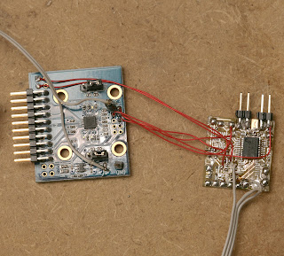
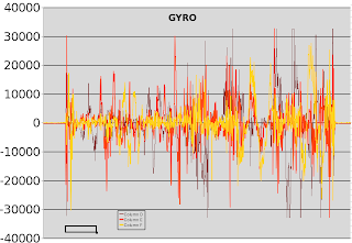
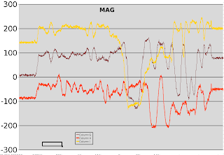
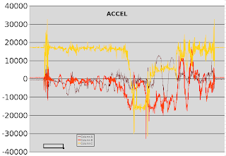
After another heroicly wasted day, the MPU9150 finally surrendered all 9 of its data streams. It has so many problems as a 1st run product, a much improved revision negating all of today's work is guaranteed. But with 2 MPU9150's lying around & a definite use, it was time to bang out a workaround just to get the data from it. The DMP firmware isn't going to happen.
Step 1: the 1st I2C command must be to set PWR_MGMT_1 (0x6b) to 0x01 to move it out of sleep mode & set the clock to the gyro oscillator. That puts 1.8V on the REG_OUT pin & 25V on the CPOUT pin. Nothing else works if it isn't the 1st command.
Step 2: set the remaining configuration registers after PWR_MGMT_1
0x37 = 0 // disable i2c passthrough
0x6a = 0 // disable i2c master
0x1b = 0 // gyro config
0x1c = 0 // accel config
0x19 = 0 // desired sample rate divider
The I2C passthrough didn't work. Only using dual I2C busses connected to the mane I2C & the aux I2C worked. The mane I2C reads the gyro & accel. The aux I2C reads the mag.
The real problem is if you simply read the gyro & accel registers, you'll always get the same value. They tried & failed to synchronize the register refreshes with inactivity on the I2C bus.
The only way to get the registers to refresh is to issue a bogus command to the mag on the mane I2C bus. I chose to read the mag status register (0x02) 1st on the mane bus to get the gyro/accel registers to refresh, then read the same mag register on the aux I2C bus to get the real value. It probably counts an unrecognized address as inactivity on the bus.
No amount of hacking could get the registers to update with passthrough enabled. It seemed to consider all communication with passthrough enabled as activity on the bus.
The aux I2C has decent enough pullups to read the mag at a decent rate. The mane I2C needs 1k pullups. It showed no obvious sensitivity to voltage changes between 2.5V & 3V. Its 1.8V regulator must make it immune to supply voltage fluctuations.
Hopefully that helps all the people with jobs involving the MPU9150 pay some of their medicare tax increases.
There's obviously some intended use involving the FIFOs, the myriad of slave registers, & the DMP instead of banging on the aux I2C manually, but any source code revealing how to do it is a closely guarded secret. The Apple model of a basic & premium developer program seems to have caught on at Invensense.


Comments
Can someone please explain why we need two slaves (0 and 1) when initializing the magnetometer?
The order needs to be
// sleep mode & clock
hardi2c_write_device(&imu.i2c, IMU_ADDRESS, 0x6b, 0x01);
// passthrough mode
hardi2c_write_device(&imu.i2c, IMU_ADDRESS, 0x37, 0x02);
// I2C master disable
hardi2c_write_device(&imu.i2c, IMU_ADDRESS, 0x6a, 0x00);
or copy the arducopter/pixhawk source code.
Hi all,
Problem: - Unable to access the magnetometer registers of MPU9150.
Output: -What I am getting is 0xFF on reading every register (corresponding to magnetometer). On the other hand I am able to access the registers of the accelerometer and the gyroscope perfectly. I have initialized the system with i2c master mode disabled and i2c bypass mode enabled. Following is the code I have used to initialize the system:-
single_byte_write(0x6B,0x01);
single_byte_write(0x19,0x01);
single_byte_write(0x1A,0x02);
single_byte_write(0x1B,0x11);
single_byte_write(0x1C,0x10);
single_byte_write(0x6A,0x00);
single_byte_write(0x37,0x02);
(‘single_byte_write(address,data) writes the data byte to the register with ‘address’ to the slave address as 0x69’)
I accessed the registers of accel. and gyro. as following:-
single_byte_read(0x75,wia_mpu); which returns 0x68 which is correct as the who_i_am register.
But when I tried to access the magnetometer registers as:-
single_byte_read_compass(0x00,wia_compass); it returns 0xFF while it should return 0x48.
In order to ensure that single_byte_read_compass()/single_byte_write_compass() works correctly I have used these functions with a change in slave address(from ‘0x0C’ to ‘0x69’)to access the registers of accel. and gyro. and it worked correctly.
(The difference between ‘single_byte_read()’ and ‘single_byte_read_compass()’ is just that the former uses the slave address as ‘0x69’ while the later uses ‘0x0C’ as the slave address. I have also tried ‘0x0D’, ‘0x0E’ and ‘0x0F’ as the slave address but the output remained the same.)
I have also ensured whether the MPU9150 is in pass-through mode. I have checked the output at the pins ‘ES_DA’ i.e. pin6 and the SDA i.e. pin24 with the help of oscilloscope which comes out to be exactly same, with by-pass mode enabled. With master-mode disabled and by-pass mode disabled the output at ‘ES_DA’ is zero always.
I have also tried the same procedure as above with not just one but many MPU9150s but the output remained the same, thus most likely there is some problem with the code.
Please help me figure it out.
Hey, I got the invensense DMP code working, it gives a nice quaternion output. Trying to figure out how to use magnetometer reading with it, any tips? here's the code https://github.com/ntavish/mpu9150-pic32
Once in Pass-through mode is enabled, to communicate with the mag you use 0x0C as the address.
I had to Write to address 0x0C at register 0x0A the value 00000001 (0x01) to put the mag into single measurement mode.
After every read cycle, the mag puts itself back into sleep mode, so you must write this register every time you wish to take a reading.
You should also, on boot, read the magnetometer Fuse ROM and get the Adjustment Values first. Store in a local variable as these do not change & are used to calculate corrected readings.
Hey Zack,
When reading from mag in pass through mode do you still address the device via the MPU9150_DEFAULT_ADDRESS =0x68; or do you use MPU9150_RA_MAG_ADDRESS = 0x0C?
If you can follow along in the Spin Language from parallax, its kind of a pain in the ass, I have a fully working driver for the 9150 that is 100% spin (no asm) so it should be easy to follow along:
http://www.mediafire.com/view/c7sv723gv07bg3l/MPU-9150.spin
Hi zack, thanks for the reply
I found one problem with my I2C code, I was sending restart transmission condition in I2C writes, which was wrong. After fixing this I have been able to port the invensense sample code to PIC32. Some progress, but still issues to fix.
Before you can get ANY readings, the MPU must be taken out of "Sleep" mode by setting PWR_MGMT_1 to 0x01.
Once that config register is set, you should be able to set the remaining config settings & read from the MPU.
I too have had many issues with this module. I have 3 drivers for it, one in Assembly, and 2 in Spin. Only 1 works like it should 100%. The others, either the accel is wrong with everything else right, or everything else is wrong but the accel, depending on the code I run.
Fyi, Writing 0x00 to all but 2 registers on the MPU will reset the register to factory default (off).
Hey, I've been trying to get imu9150 to do anything at all. I started with porting the invensense code for msp430 to my platfrom(pic32), it used to never be able to load the firmware. I left that for a while to just try and get the raw readings, I can't even get those to work :(
One simple thing that should work right after reset is to clear the sleep bit in pwr_mgmt_1 register, I write 0x00 to it, then I read it back as 0x40(sleep bit set). I2c does seem to be working otherwise, like I can read WHO_AM_I
this two were the first commands I did to test raw readings, after that, I tried a few things, like your config, and some in the comments, all give me readings as zeros.
Any ideas to what I could be doing wrong?
-
1
-
2
of 2 Next