Daniel McKinnon's Posts (9)

Sort by
3D Robotics

I recently wrote a little post designed to help those coming from a drone background pass the Fundamentals of Surveying exam, which I believe is an essential step to actually getting value out of drone data. Let me know what you think. Agree?

http://www.ddmckinnon.com/2017/06/20/becoming-land-surveyor-trainin...

When I joined 3DR two and a half years ago, I had a very broad mandate: define the product that will shepherd us from selling low-margin consumer electronics to high-margin enterprise tools. The figure Chris Anderson, my boss, published in Harvard Business Review several weeks ago, was nearly identical to the one I saw on my first day on the job. The mission was clear–go forth and get us to the green line.

At that point, it was not clear if the green line would be attained by hardware, software, services, or some innovative combination of all three. This uncertainty seems hard to believe in the summer of 2017, but it’s important to remember that the drone world has moved faster than any other in tech history. In January 2015, when I started at 3DR, DJI Phantom 2 Vision was struggling against the GoPro-carrying equivalent, Iris+ was a bleeding-edge RTF platform, and Parrot Bebop wowed the world with its solid-state stabilization. Drones were weird tech curiosities purchased over the internet, not consumer-grade toys that occupied entire aisles at Best Buy. To put this in perspective, iPhone 6 was released in September of 2014. If I handed a Mavic Pro user an Iris+, she would hardly recognize it as a drone. If I handed an iPhone 7 user and iPhone 6, she would feel right at home.

Digression aside, there were very few constraints applied to building 3DR’s first commercial product. Back then, a services team existed to build custom hardware for several enterprise clients, a handful of large companies were buying components for their own custom airframes, interest was swirling around selling a supported version of Arducopter, a handful of serious firms were using off-the-shelf Iris+s for mapping and inspection work, and we offered a joint mapping SKU with Pix4D. Through a rigorous customer development journey that was inspired by Four Steps to the Epiphany (.pdf link from Steve Blank’s course), I investigated nearly every vertical that could benefit from drone hardware, software, or services. I climbed cell towers, inspected hail-damaged roofs, descended into quarries, visited construction sites, and rode along with police. Much of this activity is covered in a podcast interview that I did with Ian Smith of Commercial Dron..., but the key takeaways were that 3DR could compete best in software, that software would eat most of the value in commercial drones, and that AEC (architecture, engineering, and construction) stood to gain the most from drone technology. After narrowing our focus, we set to work building Site Scan, a broadly focused product for mapping and monitoring construction sites.

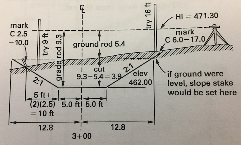
The learning did not stop there. After shipping Site Scan, we continued to learn and iterate. While many personas across AEC benefit from drone data (an owner may want a progress update, a superintendent may want to understand how work was performed, a PM may want to know if adequate materials have arrived, and so on), introducing new data into an old industry is always problematic. For example, while a PE may love to use drone data to walk back through time to understand where the post-tension cables lie underneath a concrete slab, collecting and interpreting a new data stream represents a significant burden on his day-to-day activities. Through our continued rigorous customer development, we learned that civil engineers, earthworks, and design firms spend a significant amount of money commissioning terrestrial topographic surveys accurate to one-tenth of a foot. To generate this type of survey, a firm will send out a crew with a robotic total station or GPS rover and shoot a point at some specified grid interval (25 feet or 50 feet are typical). From the grid elevations, contours, cut/fill diagrams, earthworks designs, and earthworks bills are generated. A nice example shamefully stolen from some corner of the internet is shown below.

When analyzing these topographic surveys, we learned that the exact same data product could be generated 4-10x faster and cheaper with a drone. Unlike many of the other strong use-cases in AEC like progress monitoring, pre-bid site capture, stakeholder communication, and QA/QC, the drone data served as a direct replacement for something that our users were already doing. Instead of forcing two new behaviors (new way to capture and new data to interpret), users performing topographic surveys with drones only had to learn one (new way to capture). This led me to the conclusion that, while drones can do many, many things, autonomous drones are primarily a tool to decrease the cost and collection time of topographic surveys. For specifics, check out our case studies with Bogh Engineering and All-American Surveying.

As I begin to chew on this concept, I started bouncing ideas around with Christian Stallings, the UAS lead at McKim & Creed, a large engineering and geomatics firm. At McKim & Creed, they have used drones for everything from monitoring erosion on a sensitive beachto surveying an active landfill, but each use-case is fundamentally hinged upon topographic survey. Toward the end of our conversation, Christian said, “Dan, since you’re so interested in survey now, you should become a surveyor. If you know a little math it should be easy to pass the test.” As in engineering, surveying is governed by NCEES, the National Council of Examiners for Surveying and Engineering, and one must pass the Fundamentals of Surveying exam to become a Land Surveyor-in-Training. I had previously passed the Fundamentals of Engineering exam for my role at Exponent, so I had some familiarity with the NCEES and decided to take Christian’s off-hand comment as a challenge. Besides, as a huge disciple of the method acting school of product management, I knew that building for surveyors meant becoming a surveyor. The next day I registered for the FS exam.

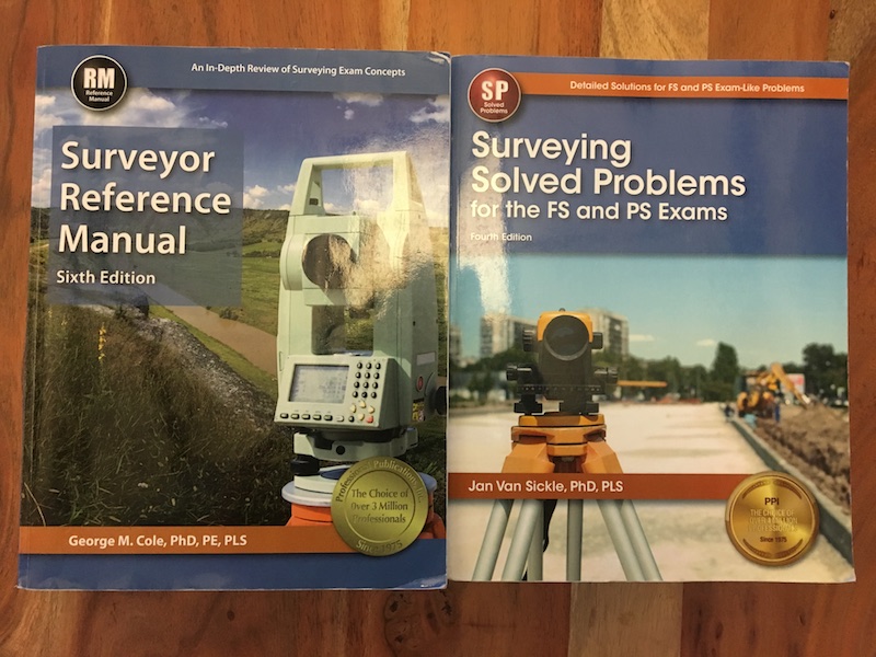
And then I waited. And waited. I scheduled the exam for a month out, so I had plenty of time to study. Right? I bought George Cole’s Surveyor Reference Manual, Jan Van Sickle’s Surveying Solved Problems, and the official FS practice exam and printed out the reference manual provided during the exam. The weekend before I was scheduled to sit for the exam, I cracked Surveyor Reference Manual and began studying.

First off, I would strongly recommend against this approach. The FS exam is fairly challenging. It covers obscure geometry and trigonometry problems that you haven’t seen since high school, mainstream three-dimensional calculus that you haven’t seen since college, and esoteric property law that you likely have never seen if your background is not in survey. Fortunately, the Surveyor Reference Manual does a tremendous job covering each of the topics. Those coming from a survey or civil engineering background will likely have a totally different approach to studying, but those coming from technology who want to learn more about the industry could probably benefit from following my approach below.

To begin, I would recommend flipping through every section of the Surveyor Reference Manual to attain some rapid-fire familiarity with all of the topics.

Math

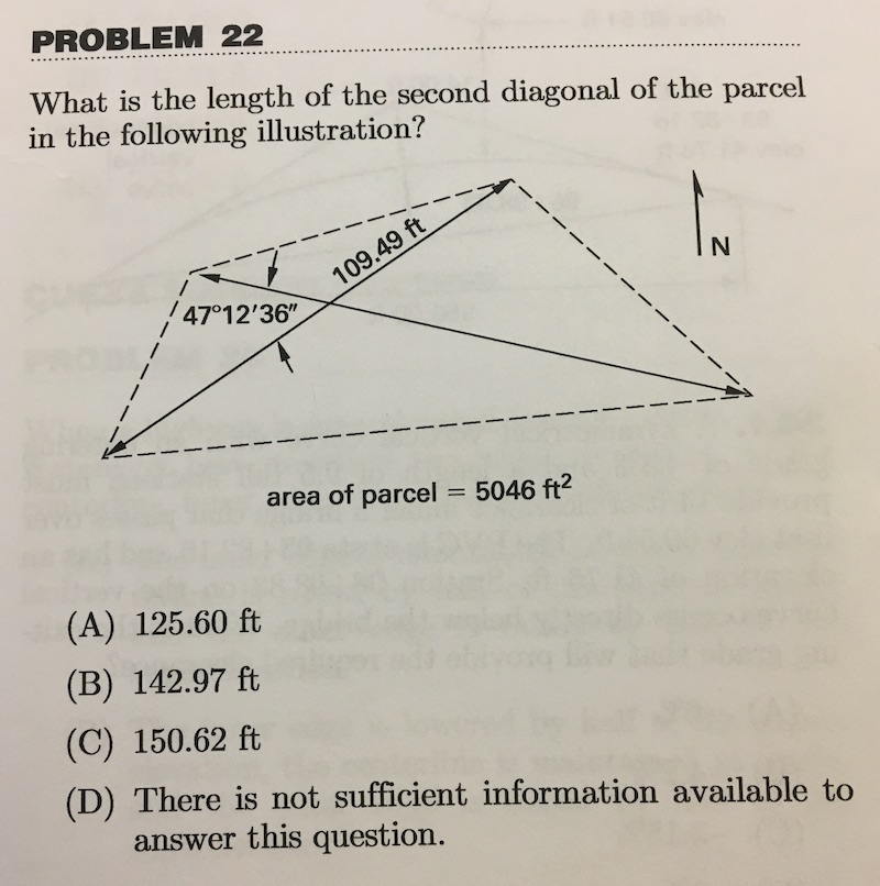
This guide is written for someone with a good math background, but minimal recent experience with geometry. It is critical to refamiliarize yourself with trigonometric and geometric identities for oblique triangles. A strong plurality of questions on the exam involve some kind of oblique triangle calculation and I am guessing you haven’t thought about the law of cosines for a decade. You must understand how to solve a triangle from an area and three angles, two angles and a side, and so on. Likewise, be comfortable solving a circle given a radius and a chord or two other pieces of information that entirely define the shape. The problems below show examples of both of these.

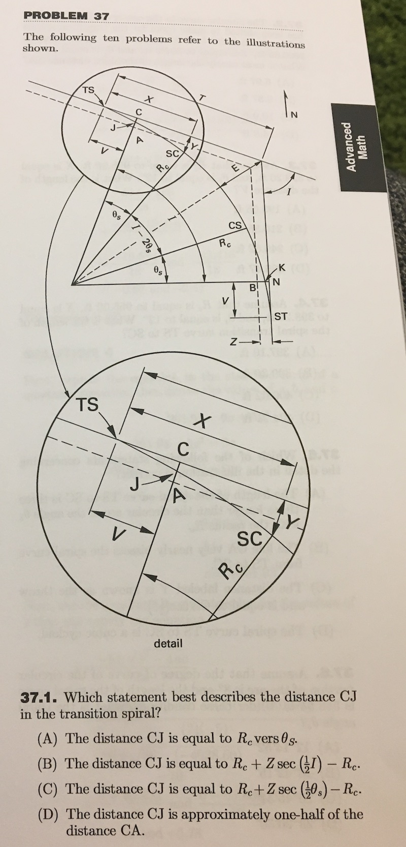
If you can nail these two concepts and briefly remind yourself how to calculate volumes of solid rotations, you will crush the math section. It is important to remember that many relevant formulas will be given in the reference manual. Keep the reference manual close when studying so you know what you do and don’t need to commit to memory.

Field Data Aquisition

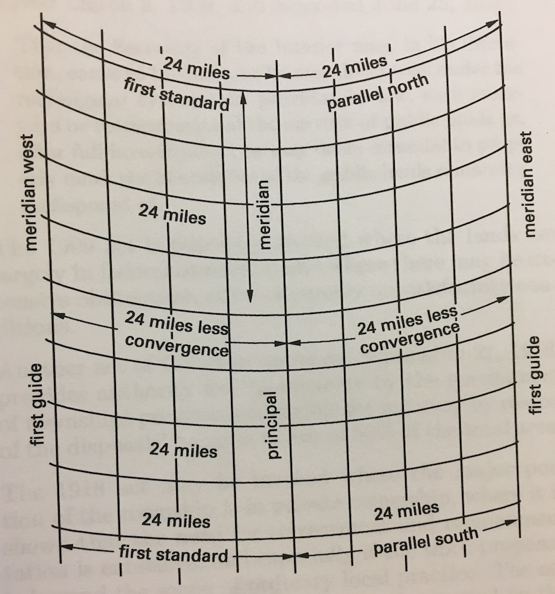
This part will be super unfamiliar but is critical for understanding how surveyors work today because so much of their behavior is rooted in history. Briefly, 66-foot Gunter’s chains and 100-foot tapes are still used as units of distance measurement (always remember that one acre is equal to ten square chains) and a dozen or so questions on pin counting, back-sighting, leveling, and compass survey will appear on the exam. Because these questions cover several centuries of technical survey history, my best recommendation is to pretend you are surveying with these archaic tools and try to understand the process rather than commit individual steps to memory. For example, when a question on marking pins arises, think about how you would use the pins rather than memorize how many pins will be left in each of the chainsman’s hands. Using this technique, I scored well on this section of the exam, despite spending minimal time studying.

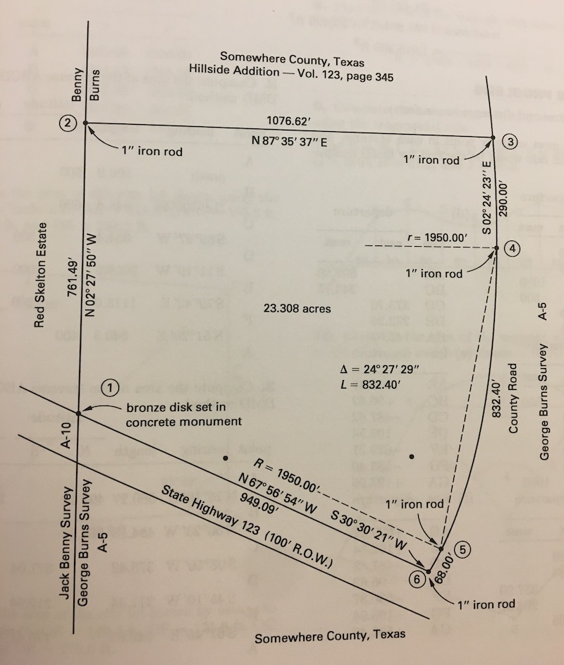
In addition, it is critical to remember that many of the concepts introduced in the section will apply to every section. The math problems are generally not straightforward math problems, but rather word problems that one must use survey understanding to translate descriptions into numbers. An infinite number of problems could be derived from the diagram above, but if you are not familiar with field data acquisition basics, it would be very difficult to solve any of them.

Plane Survey Calculations

This section simply combines the previous two. After a few hours of studying, you will likely be totally comfortable with the math, so try to spend time solving problems from this section that require you to set up the math problems using your knowledge of field data acquisition. When you get stuck (grrrrr… How do I calculate the central angle of an arc from a chord and two stations?), return to the previous section for help. A solid 40% of the exam could be traced back to this section, so you must get pretty comfortable with solving these–and fast. You have an average of 3 minutes to answer each question, so there is no time to derive relationships that are sometimes necessary to solve systems of oblique triangles. Try to commit the basic frameworks to memory.

Geodesy/Survey Astronomy

Finally an easy section! If you have been involved in drones or GIS to any extent, this section should come naturally. I would breeze through this section to make sure you understand the basics of GPS, datums, projected coordinate systems, and other GIS fundamentals, but your study time will likely be better spent elsewhere.

Cadastral and Boundary Law

This section is nasty. There is no way around it. Around 30% of the exam is composed of you-know-it-or-you-don’t questions regarding survey law. Unlike the previous sections, it is very difficult to divine or derive from first principles the answer to these type of questions. I am strongly unmotivated to commit trivia to memory, but that is exactly what is required here. I enjoyed giving this section a quick read to understand the origins of property law, but I did not spend adequate time memorizing the various terms, rules, and exceptions to those rules. If you are like me and have no inclination for flashcards, I would recommend quickly scanning the section and identifying common themes that can be used to answer more specific questions and back out the number of themes you need to commit to memory.

If you are a strong memorizer, you can guarantee yourself a pretty good start on a passing score by simply memorizing most of the concepts in this section.

Mapping

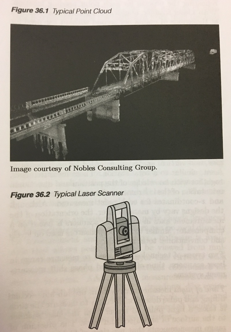
After the experiencing the heartless gauntlet of cadastral and boundary law, you earn a rest in the world of mapping. Coming from the drone world, the mapping section should be very straightforward. You must understand the principles of photogrammetry, contours, control, GIS, and LiDAR. I read this section mostly out of interest and curiosity and didn’t return to it until the exam.

Specialty Surveying Areas

This is where you should spend the majority of your study time for two reasons. First, every problem in this section requires knowledge of each of the previous. You are not going to calculate the staking pattern of a curve in a highway without geometry, survey fundamentals, plane survey calculations, and possible boundary law. Second, and most important, your customers/competitors are doing this type of work right now. As I mentioned earlier, drones are fundamentally a topographic survey tool. This section covers topographic surveys in depth. Perhaps your tool involves construction staking. Drones and other tech tools can help with that as well. I would encourage you to solve a handful of problems from start to finish and really think about how your tool could either increase speed, accuracy, or safety. Put yourself inside the head of the survey tech taking measurements for a cut/fill estimation and visualize the labor required versus your solution. Visualize the final deliverable and understand how the data are manipulated into a final product. Even better, if you have time, connect with a survey crew and try your newfound knowledge in the field. This section only represents 10% or so of the exam, but these tend to be the most time-consuming questions. Give yourself plenty of time to savor them by saving them until last.

Computer Programming/Business Management

This final section deserves a quick review, but should not present any kind of challenge. Understand how to select projects by NPV, how to make ethical decisions, and the basics of logic and you will ace this part of the exam. Consider this a 10-question gift from NCEES.

My results

In the end, I probably studied a solid 20 hours for this exam but would have been more comfortable with more time (I suppose this is a truism). I calculated that I knew the answer to 75% of the questions with good-to-excellent certainty and guessed on the rest. Assuming that I nailed 90% of that 75% block and 33% of the rest, I likely nailed about 75% of the questions, which turned out to be a passing score. NCEES doesn’t appear to publish any guidelines on the raw scores needed, so this may be the only quantitative estimate on the internet.

I have not yet filled out the reams of paperwork needed to become a California-licensed Land Surveyor-in-Training, but I am excited to join their ranks and that I have taken the time to learn the fundamentals of the profession. The professional empathy I have gained by going through this somewhat painful process has already paid dividends in my role at 3DR and I would highly recommend that anyone in the space follow my lead. Product management by method acting is pretty darn powerful. After all, the best way to know the customer is to become the customer.

Read more…
3D Robotics

3689704355?profile=original

I banged my head against a while for a while learning to share drone data in Mapbox and, now that I've got everything figured out, think it is a lot of fun and I thought I would share lessons learned on DIYD. Unfortunately, running JavaScript from within a blog post is non-starter, so you will have to cruise over to my blog to check out how some of these things actually work. All of the images here are just static representations of the interactive maps.

Autonomous flying vehicles capture all kinds of interesting GIS data–photos, projected photos, and flight logs, to name a few. Furthermore, drone imagery can be processed into other GIS data products like orthomosaic images and point clouds that become infinitely more valuable when combined with traditional GIS data sources like property boundaries and civil engineering diagrams. That said, sharing these data off-line is quite challenging. Massive geotiffs are painful to open in heavy GIS software like ArcMap and QGIS, individual images are troublesome to keep track of when not associated with a map, and flight logs are near useless in their raw .tlog or .bin form. Our friends at Mapbox have assembled an incredible (and free up to a substantial quota) toolkit for sharing all of these data in a simple webview format.

Follow these instructions to create an interactive map showcasing your drone data like the one below, whose source code is available at https://github.com/dmckinno/Mapbox. For this particular example, I overlaid a property boundary and fantastical building footprint kmls, an orthomosaic geotiff, and a handful of images viewable by clicking on the location at which they were taken, but essentially any GIS vector or raster data are sharable using Mapbox.

  1. Create an account over at https://www.mapbox.com/studio/signup/.
  2. Open Mapbox Studio. If you are not interested in adding interactivity to your maps, you can share all of your drone data without writing a single line of code. Simply upload your data a a tileset and add your tileset to a style

    .upload-tileset

    Mapbox accepts raster data in the geotiff format and vector data in the kml, which can be generated from Arducopter .tlogs using Mission Planner, gpx, which is the standard output from handheld GPS devices, GeoJSON, a GIS standard that is easily passed between systems, .shp, an open ESRI format, and .CSV formats. After uploading any of these file formats, Mapbox will slice the data into either vector or raster tiles that can be beautifully navigating on the web.

    Note you are unable to display a single nadir photo or a point cloud using Studio. To display a single nadir image in Mapbox, you must write a few lines of JavaScript (see below for examples). If you would like to display a point cloud, you must first use laslib or a commercial tool like ArcMap to convert to a geotiff.

    Once you have uploaded your tileset, create a new Style.


    style

    Choose the desired basemap, add your tileset(s) to the map, and click “Publish.”


    mapbox-studio

    Mapbox will take you to the “Preview, Develop, and Use.” Copy and paste the generated URL and send it to all of your friends. This particular example is available here.


    preview-and-develop

  3. Great! That’s the easy part. Static maps are nice, but Mapbox has a host of excellent examples that guide you in creating interactive maps displaying a wealth of different data types. First, the structure. Please clone my example repo at https://github.com/dmckinno/Mapbox to follow along. 

    Tilesets uploaded via Mapbox Studio cannot be manipulated by the user viewing them in the browser. To build the types of interactivity that I showed in the example above, you must write a few lines of JavaScript.Fortunately, this is quite straightforward and nicely mirrors the GUI options in Studio. To add a layer, use


    map.on(‘load’, function () {

        map.addSource(‘ortho’, {
            type: ‘raster’,
            url: ‘mapbox://dmckinno.8u0goq8l’
        });
        map.addLayer({
            “id”: “ortho”,
            “type”: “raster”,
            “source”: “ortho”,
            “source-layer”: “OrthoImage-6x2l6d”,
        });
    });

    This is a combination of the map.on and map.addLayer functions. I don’t know enough about JavaScript to explain exactly why they are both needed, but they are always together. I believe a layer is created and then placed on the map. In this case, I am adding a raster from a given Mapbox URL (this is creating by concatenating mapbox:// and the Map ID shown inside the tileset view) and placing it on the map with the ID “ortho.”

    map-id

    I always keep the source and the ID the same, but I’m sure some Mapbox wizard understands why they may be different in certain cases. The source-layer comes from the individual layer within the tileset. The is irrevelevant for rasters, but important if a vector tileset contains several different features. Nonetheless, the source-layer is available in the “Raster tileset” or “Vector tileset” tab in the tileset view.

    source-layer

    Vector layers are added in a similar fashion.

    map.on(‘load’, function () {
        map.addSource(‘views’, {
            type: ‘vector’,
            url: ‘mapbox://dmckinno.9erzotdj’
        });
        map.addLayer({
            “id”: “views”,
            “type”: “circle”,
            “source”: “views”,
            “source-layer”: “redhorse_photos-6besux”,
            “paint”: {
                “circle-color”: “#ffffff”,
                “circle-radius”: 3
            }
        });
    });

    The only differences arise in the options available for displaying the data beautifully. Vector data can be painted with different colors, thicknesses, fills, and opacities. Here, I simply drew white circles that indicate photo locations, but more complex vector layers can be displayed in infinitely complex and beautiful ways. The Mapbox documentation walks through the options in painstaking detail.

  4. Now you have your orthomosiac and raster data loaded, but you may want to augment the orthomosaic with individual nadir images. If you calculate the coordinates of the four corners of the image using the altitude of your drone and the focal length of the camera using simple geometry, you can display nadir images as psuedo-orthomosaics using the code below.


    map.on(‘load’, function () {

        map.addSource(‘photo1’, {
            type: ‘image’,
            url: ‘http://www.ddmckinnon.com/wp-content/uploads/2016/09/DJI_0202.jpg’,
            coordinates: [
                [-105.2311759, 40.0848768],
                [-105.2335889, 40.0851527],
                [-105.2333181, 40.0865392],
                [-105.2309051, 40.0862633]
            ]
            });
        map.addLayer({
            “id”: “photo1”,
            “type”: “raster”,
            “source”: “photo1”,
        });
    });

    It is somewhat challenging to embed two Mapbox maps in a single WordPress post (I use Code Embed, but please let me know if a better way exists), but an interactive map is available here and an image preview below. Note that because the image is not tiled, it is much less responsive than a true tiled orthomosaic.


    nadir-image

  5. The final vector layer type you may be interested in displaying is a image locations. It is often helpful to show where images were taken on a map and be able to view them based on context, whether project appropriately on the basemap or not. To do this, you must create a .kml, .shp, or .geojson file from image EXIF data. If you only have a few images, you can easily do this manually, but if I would recommend using the exif-to-geojson tool for more than a handful.Once you have the geojson file containing all of the photo information, add a description field with the image URL and any text you like to each image. You can see another nice example of this in the map of my motorcycle trip.


    “data”: {

        “type”: “FeatureCollection”,
            “features”: [{
                “type”: “Feature”,
                     “properties”: {
                        “description”: “<img src=”YOUR IMAGE URL HERE”> and any text or                       links you like”
                    },
                    “geometry”: {
                        “type”: “Point”,
                        “coordinates”: [YOUR LONGITUDE, YOUR LATITUDE]
                    }
            }]
    }

  6. Now that you’ve added all of your layers, you likely want to include some interactivity. I’ve played with all of the Mapbox examples, but most relevant here is the ability to show and hide layers and show images upon a click. For my example above, I copied and pasted from Mapbox with minor modifications and I recommend you do the same, making sure that you grab every line that you need.
  7. And voila! Now you have all the tools you need to share your drone data with all of your friends and followers using Mapbox and a few lines of JavaScript.
Read more…
3D Robotics

As always, this post is mirrored over on my website with the rest of my musings on drones at http://www.ddmckinnon.com/category/drones/

3689698482?profile=original

I am as excited as anyone in the commercial drone field for the passage of Part 107 and the relaxing of the currently extremely restrictive rules on commercial UAS usage, which will dramatically increase adoption of tools like Site Scan, the product that my team at 3DR has been building for the last year.

However, just registering to sit for the exam requires a guide itself. Startlingly, this is even more painful than the process implemented by NCEES for the Engineer in Training and Professional Engineer exams.  The FAA doesn’t appear to have evolved in the last 50 years. All registration is done by phone, all study guides are published in non-semantic pdf documents, and all instructions are scattered about a patchwork of different public and private websites and documents. I hope this post can serve as an easy-to-digest, authoritative guide for registering for the exam.

  1. Find a test center near you. You can either look through the FAA’s awful official test center list here or use a 21st century web app like this one.

    3689698430?profile=original
  2. Despite the conflicting information out there, you cannot register for the test online. You must call or email to schedule the exam.
  3. Don’t call the test center directly. They are not in charge of scheduling. You must call the mothership, which in this case is not the FAA, but PSI, a private company with which the FAA has contracted to administer the test who has published very dense website explaining some of the procedures. For some reason, PSI gives two numbers, neither of which were answered on my first attempt, 1-800-211-2754 and 1-800-733-9267.
  4. Once you get through to the operator, I spoke with Deborah who was amazing, you will walk through availability and testing centers. The Oakland test center’s schedule was wide open, so I don’t think this is terribly popular yet. The test center takes a credit card over the phone for the $150 fee.
  5. Prepare everything you need to take the exam. You must bring a photo ID with a current address. If the address on your ID is not current, you must bring a utility bill or other fairly official piece of documentation.
  6. Study! The exam ain’t easy and includes quite a bit of general aviation knowledge with which typical commercial drone operators won’t be familiar.

And that’s it! I will report back when I take the exam on Monday.

3689698281?profile=original

Read more…
3D Robotics

3689678881?profile=original

I had so much fun playing around with DroneKit Python over the last month or so, that I thought I would try my hand at DroneKit Android. Specifically, I was interested in building a customized version of Tower. As always, this blog post is cross posted on my blog with a little nicer formatting here.


The DIY Drones community is probably well aware of Tower’s expansive capabilities as a mobile ground control station, specifically with regards the built in autonomous mapping and scanning modes. Some tens of thousands of users are currently leveraging Tower to control their Pixhawk-powered drones, many of these for small business or large enterprise. However, these commercial users are stuck with a multitool when all they need is a knife. Tower has so many features and functions that it can be quite overwhelming for first time users to create even simple survey. Furthermore, it is fairly easy for even advanced users to make simple mistakes like accidentally pushing the drone into ACRO using the drop down menu up top.


For my first DroneKit Android project, I set out to create an Agribotix branded GCS for Solo AGCO Edition. This isn’t any kind of official AGCO product, but just a fun project I thought would help me learn about DK-Android.


Key features I wanted to explore in DroneKit Android were how to:

  • Change styling, colors, and logos

  • Remove unnecessary flight modes

  • Fix camera settings

  • Remove hobby oriented settings

  • Force a UDP connection


While this project is obviously mostly an exercise in deletion, it served as a great introduction to what functions are available in DroneKit Android, how code is split between Tower and 3DR Services, and how a basic Android app is structured. Prior to this undertaking, I had never touched a line of Java or Kotlin or worked with an Android app, so I will assume the reader hails from a similar background.


I hope this guide inspires/enables some of you to create your own custom versions of Tower! My example apk is available here and my my source code is here.

Step 1: Get ready


If you aren’t already familiar with SITL, DroneKit, git, and the various developer tools I’ll mention here, head over to my Idiot’s Guide to DK-Python: A Journey to WHOZ CHILLIN and give it a quick read. You will be using many of the tools and concepts discussed previously to debug and test your custom version of Tower.


Note: DK-Python is fairly simple and well documented. DK-Android is not. If you are interested in an easier journey to a custom GCS, it may make sense to work in Python.


Next, download Android Studio. Google has built an incredible Integrated Development Environment (IDE) for building Android apps and you will be using it to do all of your work on Tower.


The Tower source code comes next. Because Tower is open source, all of its source code can be downloaded from the DroidPlanner GitHub account. Run


git clone https://github.com/DroidPlanner/Tower.git


from the terminal in the directory where you’d like to work on your version of Tower. Git will automatically download all of the files you will need.


Next open Tower in Android Studio. Alternatively you can use the VCS ⇒ Checkout from Version Control ⇒ GitHub flow to automatically import Tower into Android Studio.


Android Studio will then attempt to build the Gradle, which must succeed before you can do anything. If you just installed Android Studio, it will fail because you will need to install both the latest Android SDK and BuildTools. Wait for the Gradle build to fail and follow Android Studio’s instructions to get both of these items installed.


Finally, it’s possible to test your app on either a simulated device or a real one. On my computer, the simulated device runs very slowly, so I prefer to debug using a real tablet. To do this, you must plug your tablet into your computer’s USB and set it to developer mode. Briefly, find the Android Build Number section in settings and tap it seven times. After the seventh tap, you will see Developer Mode enabled and you will be able to run your code on the connected tablet.

Step 2: Build Tower


Now that you’re ready to roll, try building Tower yourself. First, click Run ‘Android’ under the Run menu. Assuming you’ve followed all the instructions in Step 1 successfully, Android Studio should compile the Tower source code and spin up a copy of Tower on your connected device. Cool! Now you never need to download compiled .apks of open source projects. You can just compile them yourself.


Go ahead and start up an instance of SITL and connect your compiled version of Tower, which should be called Tower debug on your tablet. You should be able to control your virtual copter just like the you can using the production version of Tower available in the app store.


Running your program is great for quickly testing your changes, but you will need to compile your own .apk for distribution. Try clicking Build APK under the Build menu, building your own version of Tower, and installing it on an Android device. Easy!


Step 3: Android app basics


I am definitely not the most qualified person to write this section and likely will have some errors in my assumptions, but I think my basic understanding is generally sound. If any of the Android wizards out here have improvements or corrections, I would love to roll them in. However, having spent some time bumbling through Tower’s structure without any background in Android applications, I hope I can provide a more accessible view into how to start digging in.


When you open Tower in Android Studio, you’ll notice two high level menus: Android and Gradle Scripts. Android is where most of the meat lives, but some of the files found within Gradle Scripts are responsible for very high level functions like the app name.


2016-01-18 04.59.32 pm.png


Within Android, you’ll see manifests, java, and res. manifests dictates what types of devices are compatible with our app. When you open the xml file within manifests, you’ll notice most of the file is concerned with various hardware configurations. For this project, we don’t care about hardware, but you might imagine that for your custom version of Tower, you might want to restrict users to connecting over Bluetooth and thus would like to throw up an error if a user tried to run your app on a tablet that did not have Bluetooth capability.


The java folder contains, not surprisingly, all of the java files that provide the structure of the app. However, in an Android application, the java files in many cases only serve as a general framework into which content is populated from the xml files found in the res folder. This will become abundantly clear as we walk through the tutorial, but Tower is a delicate dance between the java files in the java folder and the xml files in the res folder.


Take a minute to scan through the java and res folders with Tower open by your side and see what you recognize. I certainly was pretty amazed by how much I was able to understand by just generally scanning the code while poking through Tower. If there is a specific feature you are interested in, try Find in Path, Shift+Command+F on a Mac, and you generally can see where in the code base a specific feature resides.
 

Step 4: Let’s try some easy stuff


So you think Tower is a boring name? Me, too. Within Android Studio, open the Gradle Scripts/build.gradle (Module Android) file. Head down to lines 140, 148, and 154. You’ll notice that you can replace Tower with a name of your choosing. I used Agribotix for my example, but let your creative juices flow.


Don’t like the Tower logo? Replace the ic_launcher.png logos found in res/drawable/ic_launcher with your own. The different files are for different resolution icons that are displayed on different size devices. If you want to be really fancy, you can use an online tool like this one to automatically generate all of these files from a vector image.

Screenshot_2016-01-18-16-58-24.png


Want to establish some branding within the app? The sidebar seems like a good place to start. Head to res/layout/nav_header_main.xml. You’ll see something like the image below. The screen is split between Android Studio’s best guess as to how nav_header_main.xml will appear on an device and the actual .xml file. If you CMD + click on some of the elements, you can see how they are linked to the rest of the code. Try it and see. After playing around for a few minutes, it should be fairly obvious what’s going on inside this .xml file.


2016-01-18 05.02.23 pm.png


Now, let’s get to your custom branding. You can either do things the hard way or the easy way. The hard way is scan through the text and identify which lines of code likely correspond to which design element. Here, is is fairly obvious that android:text= specifies what the text in the header will say, but that’s not always to case. However, Android Studio is pretty amazing. You can simply click on the item of interest, say the text, and Android Studio will highlight what code is responsible for that element. Go ahead and change the background color, logo, and text to match your branding.


Screenshot_2016-01-18-16-58-47.png

Great, now you should understand the basics of how Tower, and Android apps in general for that matter, is structured from a design perspective. I just identified a few specific touch points here, but with some pretty straightforward digging, you should now be able to completely own the style and design of Tower.


After you’ve tinkered to your heart’s content, go ahead and Run ‘Android’ or build an APK and see how it looks.


Step 5: Let’s dive a little deeper


Now that you own the design, let’s start to own the functionality. One of my biggest issues with Tower, especially when showing it off to a commercial user interested in mapping, is the 15 flight modes available from the telemetry bar. It is far too easy for a user interested in autonomous flight to accidentally kick the copter into ACRO mode and cause a crash. Let’s fix that.


Screenshot_2016-01-18-17-15-24.png

This is the first time where we will be working at the intersection of Tower and 3DR Services. You’ll notice that if you navigate res/layout/fragment_action_bar_telem.xml, you’ll find the design responsible for this feature. However, what you will not find is the ability to add or remove menu items using a simple .xml file. Rather, you will see a reference to android:id="@+id/bar_flight_mode" when you click on the flight mode piece of the telemetry bar. If you search your app for that string, you will find a java file called ActionBarTelemFragment.java.


If you stare at this file for long enough, you will realize that the menu of options in the telemetry drop down is populated by FlightModeAdapter.


2016-01-18 05.26.01 pm.png


If you CMD + click on FlightModeAdapter, Android Studio will take you to a file called FlightModeAdapter.kt, which is written in a language called Kotlin, which is similar to Java. It may be worthwhile to stop at this point and download the Kotlin plugin for Android Studio to make your code look a little more beautiful. Inside FlightModeAdapter.kt, you will see that there is another layer to the onion.


2016-01-18 05.28.13 pm.png


Tower is pulling the flightModes from a variable called VehicleMode. CMD + click on VehicleMode and you’ll notice that Android Studio takes you to the locked VehicleMode.java. This file is locked because it is not actually part of Tower, but rather 3DR Services, which provides many of the functions called by Tower and DroneKit-Android apps. While you certainly could modify that file and compile a new version of 3DR Services, it is easier to step out a layer and try to address all of our changes from the Tower level.


To do this, reopen FlightModeAdapter.kt and put on your Java hat. flightModes is simply an array populated by 3DR Service’s VehicleMode variable. To remove elements from the array, we use the Java remove command. For example, to remove ACRO from your version of Tower, include  


flightModes.remove(VehicleMode.COPTER_ACRO)


underneath flightModes. For my app, I removed every flight mode aside from RTL, Auto, and Guided.


2016-01-18 05.36.12 pm.png


Great. Now build your app and make sure everything still works.


Screenshot_2016-01-18-17-37-04.png


Step 6: Like Solo? Let’s make Tower connect automatically over WiFi (UDP).


Solo AGCO Edition users obviously are only interested in flying Solo. Bluetooth, USB, and TCP connections are painful for the uninitiated to understand and totally unnecessary. To force a UDP connection, open java/DroidPlannerApp.java. You can see that this file handles all kinds of connectivity-related functionality.


Around line 300, you’ll see


final int connectionType = dpPrefs.getConnectionParameterType();


If you look at the code carefully, you’ll see that we can cheat and short circuit the whole connection type selection process by just hard coding in a UDP connection. You’ll notice that the connectionType variable in an integer. If you do a little CMD + click digging, you’ll learn that that integer is 0 for USB, 1 for UDP, 2 for TCP, and 3 for Bluetooth. To force a UDP connection, we can just go behind all of the logic and menus and replace


dpPrefs.getConnectionParameterType()


with


1


Easy.


2016-01-18 05.46.44 pm.png


This cheat will not remove any of the UI, but no matter what connection type you specific, Tower will look for a vehicle over UDP. Which brings us to...


Step 7: Remove unnecessary menus


Now that we’ve hardcoded a UDP connection, we should remove all of the connectivity menus. And, while we’re at it, let’s get rid of everything else we find distracting. Personally, I don’t like the Flight History or Checklist top level menus and think the user is exposed to way too many settings.


Go ahead and open up res/menu/navigation_drawer_items.xml to clean up the navigation drawer and res/xml/preferences.xml to get rid of the preferences you don’t like.


You may find that with some of the xml items that you remove, you may have to find the associated Java reference and comment it out as well. This should be fairly straightforward to work through, but feel free to look to the Agribotix app for specific examples.


In this general vein, I also removed Dronie, Follow, and Land from the top level menus and everything aside from Spline Survey from the Editor screen, because the Solo AGCO Edition owners are essentially only interested in building maps. You can see how I did this by looking at what I commented out in java/org.droidplanner.android/fragments/control/CopterFlightControlFragment.java and /res/layout/fragment_editor_tools.xml


Step 8: Simplify the Editor screen for the optimal survey


Solo AGCO Edition customers use the editor screen to do only one thing: spline survey. They also user only one camera, GoPro, and should never have to play with sidelap or overlap. The mapping workflow can be dramatically simplified by hardcoding all of these values in, which is possible in java/org.droidplanner.android/proxy/mission/item/fragments/MissionSurveyFragment.java.


I started to get a little sloppy here (you’ll notice that I didn’t change the camera UI, although the camera is hardcoded to GoPro in the backend), but I hardcoded the camera to Hero 4 Black, the sidelap to 70%, and the overlap to 85%.


Screenshot_2016-01-18-18-12-43.png


Step 9: Profit?

Whew! That was a lot of work, but in the end we created a custom version of Tower that is built to address specific user needs and reinforce a platform partner’s branding. Tower is a very extensible base for a huge variety of custom mobile GCSs, so I hope this guide makes modification a little more accessible for all of the 3DR platform partners out there doing great things with Pixhawk.


Read more…
3D Robotics

3689675953?profile=original

As always, this post is mirrored on my personal blog with a little nicer formatting at ddmckinnon.com.


Ever since I moved to Berkeley and started at 3DR, I dreamed of developing an app that ran on-board Solo that would let me see who was chillin’ on my roof deck 2,200 feet from the 3DR world HQ in Berkeley. I dreamed of, as my day was wrapping up, sending Solo to snap a picture of my roof deck, post it online, and tell me if I should head home to grill on my roof with my neighbors. After the wonderful week-long hackathon we had at 3DR in December, I finally realized that dream.


And, it wasn’t that hard. While the documentation still leaves a little bit to be desired, DroneKit Python is amazingly accessible. I have a modest background in academic computing, but little to no experience with modern software engineering. After a few days of effort, which could be shortened to a few hours for those of you reading this guide, I was able to programmatically coerce Solo into some really rich behaviors driven by the on-board computer. I have enormous confidence that anyone in the DIY Drones community, after reading this guide, could do the same.


First, some basics. Solo is unique with its programmable Linux computer on board. While other platforms, including Solo, ship with a mobile SDK, mobile development is significantly more challenging (stay tuned for my guide to 3DR Services/DroneKit Android…). The computer on board Solo ships with Python, a very simple programming language, preinstalled. This makes it very easy for rote novices like me to write software that controls Solo.


OK, how do you actually do this? Follow the steps below and frequently refer to both dev.3dr.com and python.dronekit.io. The former is the Solo development guide. It describes specifically how to get your code running on Solo and how you, as a new Solo developer, can use all of the tools 3DR has built to make your job easy. The latter is the DroneKit Python documentation. It more generally describes what you can do with DroneKit Python and how to get DroneKit running on non-Solo vehicles.


Note: This guide is written for the Mac user. I’m sure there are equivalent Windows commands for many of these steps, but it will be up to the reader to track them down.


Step 1: Install Python


If you don’t have Python installed on your computer, it likely makes the most sense to install using Homebrew, a package manager for OS X that makes sure all of your packages are linked properly. Installation is straightforward and full instructions can be found at brew.sh, but essentially you just need to run


ruby -e "$(curl -fsSL https://raw.githubusercontent.com/Homebrew/install/master/install)"


from any directory in your terminal.


After Homebrew is installed, run


brew install python


from any directory in your terminal. Full instructions are at http://docs.python-guide.org/en/latest/starting/install/osx/ if you have any trouble.


Note: Brew installing this version of Python is critical to your success with DroneKit. I spent a couple hours removing multiple old Python installs and relinking tools on my dad’s computer while installing DroneKit. I would highly recommend removing any old install of Python and restarting with the Homebrew tap.


Step 2: Install DroneKit Python and SITL


DroneKit Python is the actual software that will interpret your easy-to-write commands and translate them into ones and zeros that are readable by Solo. SITL, or software in the loop, is a simulated vehicle that runs inside your computer. SITL represents the only safe way to test your code (software bugs become a lot more problematic when you’re programming the behavior of a real, physical object). I’m sure everyone on DIY Drones has heard of SITL at one time or another, but until very recently (today!) it was fairly difficult to set up.


Note: Please ignore other documentation floating around the internet regarding installing SITL on a virtual machine and follow these instructions.


Both DroneKit Python and SITL are installed using the pip command. Pip is an install command built into Python, which you just installed using Homebrew, that brings amazing software to your from the command line.


From any directory, run


pip install dronekit


to install DroneKit. Remember that, because pip is a Python command, there is no reason to specific which DroneKit we are installing.


Next, also from any directory, run


pip install dronekit-sitl


to install SITL.


Step 3: Run SITL


This step is fairly opaque in most of the documentation online, but it actually quite straightforward. SITL is a virtual computer running on your computer. Try it. Run


dronekit-sitl copter


from any directory. You will see the command return something like


Started model quad at -35.363261,149.165230,584,353 at speed 1.0

bind port 5760 for 0

Starting sketch 'ArduCopter'

Serial port 0 on TCP port 5760

Starting SITL input

Waiting for connection ....


Running this is equivalent to turning on IRIS or Solo in your front yard and without connecting to a GCS. Your simulated vehicle is sitting inside your computer at a model airport in Australia, which I imagine is Tridge’s local airfield, sending out a TCP signal from port 5760 waiting for a GCS to connect. If you decide you’d prefer that your simulated vehicle take off in Berkeley, rather than Australia, run


dronekit-sitl copter --home=37.873894,-122.302141,584,353


See what happened? Other SITL options can be accessed by running


dronekit-sitl --help


or


dronekit-sitl copter --help


You’ll notice that you can simulate a plane or a rover and change various simulated vehicle settings.


Step 4: Connect SITL to arbitrary ground control stations


DroneKit Python contains a connect command, but to actually see how your simulated copter responds to your code, you will need to connect a GCS. This is done through MAVProxy, which as best as I can tell is both a text based GCS and a way to plumb mavlink messages from SITL or a real copter to other GCSs.


Unfortunately, installing MAVProxy is not as straightforward as the rest of this guide. The best instructions are at http://dronecode.github.io/MAVProxy/html/getting_started/download_and_installation.html#mac, but to keep this guide linear I will reproduce them. Run


brew tap homebrew/science


brew install wxmac wxpython opencv


from any directory in the terminal. The first command taps a repository that is not normally indexed in Homebrew. The second command installs wxMac, which is total mystery to me, wxPython, which is also a mystery to me, and OpenCV, which is an amazing open source computer vision project from which, I believe, sprang Pix4D and Agisoft.


Next, run


sudo pip uninstall python-dateutil


sudo pip install numpy pyparsing


sudo pip install MAVProxy


The sudo part means that you are running the command as an administrator on your computer and the pip command is our old friend from before.


Now MAVProxy should be installed and you are ready to start playing with your virtual copter. Start up SITL, if you closed the terminal window, by running


dronekit-sitl copter --home=37.873894,-122.302141,584,353


Then open a new terminal window and run


mavproxy.py --master=tcp:127.0.0.1:5760 --out=udpout:10.1.49.130:14550 --out=udpout:127.0.0.1:14550 --out=udpout:127.0.0.1:14549


Notice that your SITL window has now bound to the MAVProxy master. This is because we’ve pointed MAVProxy to listen to MAVLink messages over TCP at local IP address (127.0.0.1, although 0.0.0.0 will work as well) using port 5760, all of which was specified when you initially booted up SITL. The three --out items give me three sockets to which I can connect GCSs.


You can now use MAVProxy to control your virtual vehicle (or your real vehicle if you choose to do so, to connect MAVProxy to a real vehicle connect your computer to Solo’s WiFi and replace tcp:127.0.0.1:5760 with udpin:0.0.0.0:14550). Try typing


mode guided


arm throttle


takeoff 10


into the terminal window running MAVProxy. You’ll notice your virtual vehicle will switch modes, arm itself, and takeoff. However, as interesting as it is to control a virtual vehicle from the command line, we are here to write software to control Solo’s behavior and need a visual way to monitor your virtual Solo’s behavior.


This is where the sockets come in. The first refers to my tablet running Tower, which I can use to both monitor and control my instance of SITL. The 3DR network assigned IP address 10.1.49.130 to my Android tablet, which I determined by navigating to the advanced WiFi settings menu, and Tower is set up to listen for a vehicle on port 14550. Now, when I connect my tablet to the same WiFi network on which I am running SITL, I can see my virtual copter parked near the Berkeley office and can control it just like a real copter. To connect your Android tablet running Tower, you should replace my IP address with your own.


The second will be used for running the DroneKit Python examples. We need a socket free for DroneKit’s connect command to bind to.


The third is an extra for Tower-Web, a nice web app that let’s you track the status of your real or virtual vehicle. This is nice because it lets you debug your DroneKit Python applications without an Android tablet handy, but this step is totally optional and redundant if you plan on using your tablet running Tower to visualize your virtual Solo’s behavior. To install Tower-Web, simply run


sudo -H pip install -UI git+https://github.com/dronekit/tower-web.git


from the terminal. Once the installation completes, run


tower tcp:127.0.0.1:14549


and you will bind the Tower-Web backend to your instance of SITL. Point your favorite web browser to http://localhost:24403/ and you should see your virtual vehicle flying around on your screen.


To quickly review, you now should have a virtual vehicle running on your computer that you can control using MAVProxy running in the terminal, Tower running on your Android device, or Tower-Web (sort of) in your web browser. Whew!


Step 5: Run the DroneKit Python example apps


Great! Now you’ve made it this far and are ready to start having some real fun. Let’s run the examples.


The easiest way to get the examples is using Git, which is a great and widespread tool for sharing and code on the internet. If you don’t have Git installed on your computer, we can return to our favorite program Homebrew and run


brew install git

from the terminal. Once Git is installed, navigate to the directory where you’d like the examples to be stored and run


git clone http://github.com/dronekit/dronekit-python.git


The DroneKit Python examples will download into the folder from which you ran this command. Navigate to the Vehicle State example by typing


cd dronekit-python/examples/vehicle_state/


and run


python vehicle_state.py --connect 127.0.0.1:14550


Note that we now have used all three of the sockets generated by MAVProxy (if you’d like to prove this to yourself, try connecting to 14550 with both DroneKit and Tower-Web) and the Vehicle State application will run. I’ll leave it to the DroneKit Python documentation to explain exactly what this program does, but needless to say you’ve run your first application on your virtual drone and are well on your way to writing your own.


I’d recommend running the rest of the examples, reading the documentation, and getting a rough sense of what they do. By the end of this, you should have a pretty good idea of what kinds of functionality is built into DroneKit Python and how you might write an application to control your real drone.


Step 6: Run the DroneKit Python example apps on Solo


SITL is fun and all, but we don’t read posts on DIY Drones to learn about controlling virtual vehicles. We want to control the real thing. Let’s try running some of these examples on Solo.


Simple Go To is a great one to start with. All of the locations are in Australia, so, if you don’t live with Tridge, open up simple_goto.py with a text editor (I like Sublime Text) and edit the lattituide, longitrude, and alitude in points one and two (LocationGlobalRelative(your lat, your lon, your alt). Next, test your changes in SITL and make sure you simulated Solo is behaving as you anticipated.


Once you are satisfied with your code, bring Solo out to your airfield, connect your computer to Solo’s WiFi network, and spin up MAVProxy to plumb the whole system together. For the lazy, the terminal command is


mavproxy.py --master=udpin:0.0.0.0:14550 --out=udpout:10.1.49.130:14550 --out=udpout:127.0.0.1:14550 --out=udpout:127.0.0.1:14549


You now can run


python simple_goto.py --connect 127.0.0.1:14550


from the Simple Go To’s directory and Solo will execute the Python commands and perform the mission. Pretty cool!


However, the observant reader might catch that in this case the code is actually running on your computer, not the computer on board Solo. To move the code and all of its dependencies on to Solo, we have to return to the Solo Development Guide and take advantage of some neat tools that the engineers at 3DR have written.


First, let’s install the Solo command line interface using pip


pip install -UI git+https://github.com/3drobotics/solo-cli


This CLI lets you run a number of useful commands from the terminal. For example, if you’d like to connect your computer to both the internet and Solo over WiFi, which is very useful for development, run


solo wifi --name=network name --password=network password


To run your example code on Solo, run


solo script pack


from the directory containing simple_goto.py. This command will prepare a package containing your Python application and all of its dependencies on your computer. To install and run (note that this is a single step) this package on Solo, connect to Solo’s WiFi network and run


solo script run simple_goto.py

Solo will takeoff and execute its mission based solely on the code you loaded onto its companion computer. You can verify that this by turning off your controller and seeing Solo execute its mission without an external signal in the loop.


Step 7: Controlling the camera and gimbal


Now that you’ve run the examples both in SITL and on Solo and spent some time understanding the various DroneKit Python functions, you are essentially ready to program your own Python-based GCS. It’s that easy!


However, one of the most amazing pieces of Solo is the fully controllable gimbal and camera. Simple camera functions haven’t quite made it into DroneKit Python and we at 3DR are still working to integrate all of the Solo-specific MAVLink messages into our SDK, but, because it’s close to Christmas and generosity is in the air, I will post some shortcuts here.


Both the gimbal and GoPro are controlled by MAVLink messages and DroneKit Python is backwards compatible with PyMAVLink, a great way to send arbitrary MAVLink messages to Solo. The general format of a MAVLink message sent through PyMAVLink is somewhat complicated. An example of a yaw message is below.


msg = vehicle.message_factory.command_long_encode(

        0, 0,     # target system, target component

       mavutil.mavlink.MAV_CMD_CONDITION_YAW, #command

      0, #confirmation

        90,     # param 1, yaw in degrees

        45,           # param 2, yaw speed deg/s

        1,           # param 3, direction -1 ccw, 1 cw

        0, # param 4, relative offset 1, absolute angle 0

        0, 0, 0)     # param 5 ~ 7 not used


I am no PyMAVLink expert, but, as we can see in both the comments and the MAVLink documentation for the yaw command, we use the vehicle.message_factory.command_long_encode function to pass an 11 argument message to some component. The first two arguments serve as the address of the message--0 and 0 refer to Pixhawk, which is doing the yawing. The third argument refers to what MAVLink message you’d like to send. Feel free to experiment with different messages. The fourth does nothing and the fifth through eleventh refer to the up to seven commands that can be passed through any MAVLink message. For this particular yaw command, only four are used--the amount of yaw requested, the yaw speed, the direction, and whether yaw should be absolute or relative to the position of the copter before the yaw was initialized. Now you’ve had the opportunity to look under the hood at DroneKit.


We will use a similar strategy to control the camera and the gimbal with one caveat--mavlink-solo-master is still private. We at 3DR are working hard to clean everything up for public consumption so these commands will work on board Solo, but not on your computer or in SITL.


To switch GoPro from video to photo mode, try the command below.


msg = vehicle.message_factory.gopro_set_request_encode(MAVLINK_GIMBAL_SYSTEM_ID, MAVLINK_GIMBAL_COMPONENT_ID, mavutil.mavlink.GOPRO_COMMAND_CAPTURE_MODE, (1, 0, 0, 0))


vehicle.send_mavlink(msg)


vehicle.flush()


Notice we are now using the gopro_set_request_encode variable rather than the command_long_encode, but the general format is the same. Here the system and component IDs, which were 0 and 0 for Pixhawk, are declared as variables rather than numbers. You can either include MAVLINK_GIMBAL_SYSTEM_ID = 1 and

MAVLINK_GIMBAL_COMPONENT_ID = 154 as constants in the start of your code, or just substitute these numbers for the text. Notice the MAVLink message is GOPRO_COMMAND_CAPTURE mode, which is not found on the list of Arducopter MAVLink messages. This is because it is found in the in the still private mavlink-solo-master and documentation has not yet been written. That said, I can tell you right now that switching the first bit in the message from a 1 to a 0 will switch the camera from photo to video mode. Cool!


To take a picture, I used the code below.


def take_a_pic():


   msg = vehicle.message_factory.gopro_set_request_encode(MAVLINK_GIMBAL_SYSTEM_ID, MAVLINK_GIMBAL_COMPONENT_ID, mavutil.mavlink.GOPRO_COMMAND_SHUTTER, (1, 0, 0, 0))


vehicle.send_mavlink(msg)


vehicle.flush()


Notice that this time I wrote a definition, so each time I want to take a picture in my code I can simply write take_a_pic().


To control gimbal, I wrote an eponymous definition, nadir_point.


def nadir_point():


   vehicle.flush()


   msg = vehicle.message_factory.mount_configure_encode(

           0, 1,    # target system, target component

           mavutil.mavlink.MAV_MOUNT_MODE_MAVLINK_TARGETING,  #mount_mode

           1,  # stabilize roll

           1,  # stabilize pitch

           1,  # stabilize yaw

           )


   vehicle.send_mavlink(msg)

   vehicle.flush()


   msg = vehicle.message_factory.mount_control_encode(

           0, 1,    # target system, target component

           -90*100, # pitch is in centidegrees

           0.0, # roll

           0, # yaw is in centidegrees

           0 # save position

           )


   print "mavlink message is:", msg


   vehicle.send_mavlink(msg)


   vehicle.flush()


This time it takes two MAVLink messages to get the job done, but it still does the trick. Now whenever I’d like to point the gimbal toward nadir, I simply call nadir_point(). If I wanted to be even more clever, I would write a function called point(XX) whose argument appeared in place of -90 in the pitch field so the function could be used to point the gimbal wherever I wanted.


You should now have all of the tools in your toolbox to write your own WHOZCHILLIN app.


Step 8: WHOZ CHILLIN


You can download my WHOZ CHILLIN code here. You can see that the user gets several different CHILL options. Go ahead and replace my GPS locations with your own and  give it a rip. Note that the CHILLIN app turns off the R/C failsafes. Test your code in SITL extensively before you even consider doing this.


Step 9: Future directions


But wait, you say. I promised that WHOZ CHILLIN would let me open a web browser and see an image of who was chillin’ on my roof. The code here just takes a picture that GoPro saves to the SD card that I have to pull out to take a look at. This is way too painful of a workflow to really be CHILLIN. You are right, but this is enough for now.


Instructions for grabbing stills from the video feed, setting up a Python server, and posting the result online will be contained in the next installment of Idiot’s Guide to DK-Python and soon you will be able to complete your journey to WHOZ CHILLIN.


I'll leave you with this picture of WHOZ CHILLIN at the basketball courts near 3DR.

3689675863?profile=original


Read more…
3D Robotics

3689668419?profile=original

If you answered yes to both of those questions, then this post is for you.

I've always had a special fondness for the Sony QX-1 and decided to rig up a contraption that would let me fly her with Solo. For both of you on DIYDrones who are not familiar with the QX-1, it is a light (180 g body), high resolution (20MP), endowed with a large sensor (APS-C, 15x larger than GoPro) body that receives Sony E-mount lenses (including zoom lenses), and can be controlled by an extensive WiFi API.

3689668321?profile=original

First, I had to learn how to control the camera via the WiFi API. Jaime Machuca, of Droidika, wrote a nice MAVLink wrapper for the QX-1 API, but I never quite could get it going on Solo. Instead, I deployed the pysony API, which I installed on a RasPi that I taped to Solo's belly. This RasPi connected to QX-1's WiFi upon boot, ingested the mjpeg QX-1 livestream, pipe it over HDMI to Solo App, and triggered the QX-1 to begin shooting. I could control all other QX-1 functions on the ground, but I didn't have an easy way to integrate those controls into Solo herself.

3689668436?profile=original

Next, I had to gimbal the camera. At 280g with the 20mm flat lens and a bit more with the 16-50mm Power Zoom, a brushless gimbal was probably out of the question and would have been much more difficult and expensive to build up. Because I was mostly interested in stills, I didn't particularly care about smooth video, but rather wanted a horizontal horizon and the ability to tilt the camera. I selected the RC Timer CM102, which had no problem stabilizing the camera reasonably well and holding the desired pitch.

3689668240?profile=original

These two pieces combined succeeded into turning Solo into a reasonable, but kludgy solution to capture truly professional aerial images for either general consumption or the generation of high quality maps or models. However, while this project is functional, it is incomplete. This feat of engineering contains no fewer than two PixHawks, six batteries, 20+ feet of cable, two companion computers, five ESCs, 10+ feet of strapping tape, and two transmitters.

I would love some additional feedback and support from the community to potentially turn this weekend project into something that any Solo owner could enjoy. I have a few full resolution images from both the QX-1 and GoPro along with a video of this thing in action (on my desk) on my blog, to help you answer these questions.

1) Is this something you would generally want?

2) Is a servo gimbal a problem? Servos will never succeed at delivering high quality video, but seem quite capable of stabilizing the camera for stills.

3) Would anyone be willing to help me integrate pysony and appropriate WiFi boot up scripts into the iMX6, eliminating the need to carry a second companion computer?

Read more…
3D Robotics

3689657738?profile=original

There has been a lot of discussion recently on DIYDrones about GPS accuracy, the reliability of autonomous flight modes like Return to Home, and safe flying conditions. These are all valuable discussions to be had, but it is also is helpful to consider how well GPS-based positioning works in the best of conditions.

To generate the plot above, I launched and RTLed Solo 26 times and recorded the landing position with tape. These flights were conducted on a flat rooftop in Berkeley with a totally unobstructed view of the Southern sky. I typically had 8-12 satellites for each one of these flights.

I then took an image from the air using Solo with a flat-lensed GoPro and measured the angle and distance from the takeoff zone in ImageJ. 

3689657668?profile=original

3689657751?profile=original

Over these 26 landings, the maximum deviation was over 6 feet and the mean was around 3 feet. I hope this is helpful for those new pilots in the community who are just beginning to experiment.

If more precise landing are desired, there are some excellent dev options out there like IR-Lock, which does not rely on GPS, and Piksie, which does.

Read more…
3D Robotics

3689655681?profile=original

There has been a lot of interest in autonomous mission planning and mapping using Solo since release.

Good news: mission planning with Solo is exactly the same as it was with IRIS+ or any PixHawk powered vehicle.

Better news: the tools just keep getting better.

Mapping used to involve a truck full of computers, masts, antennas, and mobile hotspots and quite a bit of brain damage sorting out logs, images, and stitching after returning to the office. Now the same work can be done with the contents of a backpack and a minimal amount of computer, drone, and GIS aptitude.

What follows is a quick guide to mapping with Solo and nothing more than the contents of a backpack. The workflow is smooth enough now that I’m confident anyone can follow along and make a map with minimal effort and expense.

3689655862?profile=original

Step one is to show up to your site with with a backpack filled with Solo, a GoPro (ideally with a 5.4mm flat lens installed), a handful of batteries (at 80% sidelap I get about 30 acres per flight at 350 feet), a patch antenna (if the area to be mapped is longer than a half a mile), an Android tablet, and a Windows laptop. I typically begin by popping powering on Solo and the transmitter, so everything is ready to go as soon as my mission planning is complete.

Next, I whip out Tower and plan my mission. While full fledged mission planning used to require desktop applications, Tower has evolved into a very capable mobile solution and offers essentially all of the functionality of its desktop counterparts. Additionally, the 3DR team has recently written up some excellent guides to using Tower that are worth checking out for even the veteran.

There's no reason to duplicate work, but, briefly, my order of operations for mission planning is as follows:

1) Connect Tower to Solo using the WiFi setting in Android


2)Open the Editor and tap the squiggly line and select “Survey”


3) Draw a perimeter around the area of interest


4) Tap the green square in the lower righthand corner to bring up the survey details. Here you select the camera lens (GoPro with a 5.4mm lens has approximately the FOV of an S100), altitude, and sidelap. I’ve found 80% sidelap to be more than sufficient for most areas. Solo can typically cover around 30 acres at 80% sidelap flying 15 m/s at 350 feet. The survey tool also provides important information related to the quality of the survey.

5) Upload the mission to Solo by tapping on the three dots in the upper righthand corner.

3689655790?profile=original

Next, turn on the GoPro and sync the GoPro time to the tablet time using the wrench icon in the GoPro app. This step is critical, but does not need to be repeated every flight. The images will be geotagged by matching the timestamp on the image with the flight log, so as the GoPro clock deviates from the tablet clock, accuracy is diminished.

After synchronizing the clocks, set the intervalometer to take a picture every two seconds. There is clearly room for experimentation here, but for most areas flying at 15 m/s and shooting every 2 seconds gives plenty of overlap (~75%, depending on altitude). This step will be eliminated when the Solo gimbal is released and camera control is built into Tower, but for now remains manual.

After the GoPro is shooting and the mission is uploaded, arm Solo and send her on the autonomous mission, sit back on your cushy backpack, and enjoy a marg. Once the mission is completed and Solo lands, stop the camera and power cycle the tablet to write the logs to the permanent memory.

Next, here is where you will really enjoy the backpack seat, open your laptop and start Agribotix Field Extractor (I believe you must create an account to download this piece of software). In the very near future, this entire process will be mobile only, but for now a Windows laptop is still in the loop.

3689655905?profile=original

Grab the SD card from the GoPro, plug it into the laptop, and connect the tablet to the laptop. Open the Agribotix Field Extractor and follow these instructions. The key piece here is that the GoPro already has its clock synced to the tablet, so the time offset is 0.

After importing and geotagging the images, Field Extractor generates a rough .kmz file that tiles the images in Google Earth locally immediately and generates a .zip file on the desktop of geotagged images. If you are an Agribotix customer and pay $49/month for image stitching in the cloud, like me, the images are automatically uploaded and stitched in around an hour. If you are not and prefer to use your own software like Pix4D, Photoscan Pro, AutoDesk ReCap, or something else entirely, you will have a nice folder of geotagged images on your desktop taken by Solo and GoPro.

While there are a lot of words above, the entire workflow is very smooth and makes mapping quite accessible to anyone interested is basic drone-based GIS and photogrammetry. Geotagging using the Agribotix Field Extractor by far the smoothest way to inject geotags onto images taken using a PixHawk controlled vehicles and image stitching in the Agribotix cloud takes all the brain damage out of using photogrammetry software. Give it a rip and post your Solo maps up here! I would love to hear feedback.

One of mine is below.

3689655876?profile=original

Read more…
3D Robotics

Belated pictorial AUVSI recap

3689651541?profile=original

Note: The image formatting is a little difficult and the number of images per post appears to be limited on DIYdrones, so I mirrored this whole post to my website where it looks a little nicer and the rest of the images can be found.

Two weeks ago I attended AUVSI to learn how the unmanned defense industry is pivoting into the commercial space and where 3DR fits into that ecosystem; give a talk on our community (including DIYDrones!); and sit on a panel moderated by Drone Analyst on drone startups. However, the time available for my mission was cut seriously short by the overwhelming and unexpected interested in Solo displayed by an enormous range of show participants. Everyone from old school, black suit-wearing Lockheed engineers to awesome startups building accessories for drones flocked to our “unmanned” Solo kiosk to ask about Solo. However, I still had a quick two hours on the last day of the show to scope out some of the exhibitors.

Toward one end of the exhibition hall there was a horde of Chinese and Korean multirotor manufacturers who all  mysteriously claimed to have engineered their own autopilots from the ground up. Hmmmmm… That 3DR ublox GPS module is pretty distinctive, even if the logo is wiped off with acetone…

3689651572?profile=original

AirRobot showed off a massive hexrotor that takes a 750 Wh battery! To give a sense of perspective, this is nearly five times the limit that can be taken on a plane. Every time the vehicle is shipped the battery must be packaged in a special flameproof case and carried by special courier.

3689651612?profile=original

MicroDrones spun out a new US-based manufacturer called Avyon. Their business relationship is not totally clear, but they appear to be making the exact same high quality vehicles stateside, but rebranding them for the American audience.

3689651442?profile=original

Drone America showed off an interesting octo at the AirWare booth. These designs nicely shroud the blades, but it can’t be an efficient way to maximize disk loading and I can’t imagine trying to travel with this.

3689651597?profile=original

This shotgun-wielding heptarotor appeared in a number booths. No one could answer any questions about it, but it appears to be some boat/multirotor hybrid with a couple of 20 gauge shotguns underneath.

3689651635?profile=original

This SenseFly eXom is truly an impressive piece of engineering. It carries a thermal/optical gimbalized camera for inspections, several simple fixed cameras for sense-and-avoid, and several sonar units for the same purpose. I never saw a flight demo, but the GCS looked impressive, if not a little overwhelming.

3689651721?profile=original

This huge Sikorsky UH-60 Black Hawk helicopter probably stole the show. I wonder if she flies PixHawk? As we were packing up, I was disappointed to see her getting loading onto a truck. I was hoping she flew in.

Read more…