Chris Anderson's Posts (2718)
Sort by
Anybody know anything about this one? It's $35 from Roboshop:
2.5dbI high gain and selectivity ceramic antenna
MMIC BGA715L7 from Infineon power amplify IC
SAWF (Surface acoustic wave filter) form Murata
HMC5983 from Honeywell geomagnetic
The Radiolink SE100 GPS Module for PixHawk exceed the limitation of IC sensitivity index from circuit schematic design to PCB placement.1 meters positional accuracy, positioning in 23 seconds and valley station keeping ability.
Specifications
Back to top
- Positional Accuracy: 1m precision when working with concurrent GNSS, 2.5m precision when working with single GNSS
- Velocity precision: 0.1m/s
- Max height: 50000m
- Max speed: 515m/s
- Max acceleration: 4G
- Max update rate: up to 18Hz
- Sensitivity Tracking & Nav.: -167dBm; Reacquisition:-163dBm; Cold start:-151dBm; Hot start:-159dBm
- Time to first fix: Cold start: 26s, Hot start: 1s
- Connect ports
- Power supply: voltage 3.3VDC+-5%, current 50~55mA
Ports
A.GPS UART interface, baud rate: 1.2K/4.8K/9.6K/19.2K/38.4K/57.6K/112.5K
- B.Geomagnetic I2C interface
There were an amazing 425 entries to the Airbus/LocalMotors drone cargo challenge, and this week judging begins to select the winners (I'm one of the judges). Check them out here.
(shown above, the fastest ArduRover yet, an electric go-kart built by Autodesk CEO Carl Bass [shown with author Kevin Kelly] and run at the Self Driving Cars track day this weekend)
From the announcement thread:
Hi everyone. The ArduPilot team has created a new Rover beta. You can download the binary directly here
http://firmware.ardupilot.org/Rover/beta/
or if your using a GCS like Mission Planner tick the box to see the Beta downloads available.If you have any comments or questions please post them in this topic and I'll do my best to answer.
Whats changed?
Fixed arming for Skid Steering rovers. You should now be able to arm your skid steering rover using the steering stick. NOTE skid steering Rovers - you will not be able to disarm. The reason for this is zero throttle full left turn is a perfectly valid move for a skid steering rover as it can turn on the spot. You don't want to be executing this and have the rover disarm part way through your turn so I have disabled disarming via the steering stick. You can still disarm from the GCS.Improved Steering Control:
For historical reason's the steering controller was using the raw GPS data without any filtering. If you have every graphed this data you will see on a rover its very spiky and all over the place. This spiky'ness was feeding directly into our steering controller and causing inaccuracies. Now we using the EKF GPS filtered data which is much smoother and accurate and the steering control has greatly improved.Improved Cornering:
Previously when corning we didn't take into account any "lean or tilt" in the rover - we assumed the turns were always flat. We have changed this to now take into account any lean so turning should be more accurate. Boat users should really benefit from this too.EKF2 improvements - its continues to get better and better.
There have been other changes but the above ones are the big ticket items for Rover users.
Thanks, Grant.
I was interested to see this in the fantastic new Maritime Museum in Amsterdam. Those big canisters on each side of the ship compass are iron slugs designed to compensate for the "hard iron" magnetic distortions of the iron ships they were mounted on. Now we do it in software, but the principle is the same.
Another great swarming demo from the Naval Postgraduate School in Monterey, California. Not a new record of planes in the sky (which is 50), but an impressive launch rate of nine drones in nine seconds. All Pixhawk-powered Skywalker X8s.
I've been using my RasperryPi's more and more with Dronecode software, including with the fantastic Navio2 autopilot shield and the slightly more basic Erle 2. I've also got Erle's new PXFmini shields for the Raspberry Pi Zero, but unfortunately no Zeros :-( Since the release of the new version with a camera port (which I need) they're out of stock everywhere. Fingers crossed they become available soon. In the meantime, enjoy Erle's post on Hackaday showing how to get a PXFmini flying:
DESCRIPTION
This project builds a Linux drone with the Raspberry Pi Zero using a BOM (Bill of Materials) of less than 200 US$. The drone uses a PREEMPT_RT patched Linux kernel, a Debian-based file system and Dronecode’s APM flight stack compiled for the PXFmini autopilot shield.
DETAILS
- Drone made with the PXFmini autopilot shield for the Raspberry Pi (available from here).
- Open schematics
- APM/ardupilot flight stack compiled for the Pi Zero (sources, instructions)
- Linux drone using a Debian file system made by Erle Robotics specially for the Pi Zero (available here). Includes a catkin workspace with the Robot Operating System (ROS) Indigo.
- Docs about the PXFmini
Great news for Solo owners: the impressive Pix4DCapture app for iOS and Android is now available for the 3DR Solo.

Quick 3D Preview Post-Flight
Right after flight, upload the images to Pix4Dcloud directly from the app and receive a Quick 3D Preview on the phone within minutes.
Once the images are uploaded, you can also download the dataset from your Pix4D user account page and open the project inPix4Dmapper Pro or Mesh on your computer.

Transfer to Pix4Dmapper
After your mission, just transfer the project from your phone to computer, either directly from the drone or via Pix4Dcloud.
With your Pix4Dmapper Pro or Mesh license, process the project in full resolution, verify and improve the project quality, edit the point cloud, export professional outputs, and measure features with survey-grade accuracy.
New Mission Manager for Android

Pix4Dcapture 3.0
Map bigger areas by creating multiple missions, which you can save, duplicate and combine into projects. Plan flights from your office and press START in the field for fast and efficient mapping, then easily visualize the images from each mission . Project details are saved and organized for optimal access.
![]()
Multiple Missions
Create a tailored mapping plan by flying multiple missions under one project
![]()
Optimal Flight Planning
Plan projects and missions in advance or on the field
![]()
Recreate Flights
Duplicate individual flight missions or entire projects for efficient mapping over time
This is an example of risk based planning for a flight across a city in the PX4 SITL. The drone avoids flying too close to buildings or through confined spaces where it might loose GPS reception. PX4's Vilhjálmur Vilhjálmsson is working on bringing this to outdoor flights this summer.
It's customary and traditional that we celebrate the addition of every 1,000 new members here and share the traffic stats. This time it's a 78,000!
Despite the site being on-and-off down for nearly a week this month as you can see on the right side of the traffic graph above (the fault of Ning, our hosting provider -- you can see the sorry story of their tech issues here), we still had more than a million page views this month. We're eventually going to have to shift off Ning, but hopefully their downtime issues at least are over.
Thanks as always to all the community members who make this growth possible, and especially to the administrators and moderators who approve new members, blog posts and otherwise respond to questions and keep the website running smoothly.
 From The Verge:
In a study published in this week’s issue of Science, researchers say this new perching ability could be key to creating insect-sized aerial robots that can help with a long-term observational tasks — traffic
The mechanism was developed by researchers from MIT for the RoboBee: a tiny flying robot first unveiled in 2013. The RoboBee weighs just 0.08 grams (that’s 31 times lighter than a penny), and has a pair of tiny wings that can beat up to 120 times per second. Previously, the bot relied on miniature tripod on its base for landings — but that meant it could only set down on the top of flat surfaces. The new mechanism will instead let it fix onto the underside of pretty much any material, including leaves, glass, wood, and brick.
The electrostatic pad itself sits on the top of the RoboBee, making it look a little like a rubber dart, and is connected to the bot via a polyurethane mount that’s essentially a squidgy ear plug. This allows the circular contact to bend and flex, meaning the microrobot can approach its target surface at an angle, rather than having to line exactly parallel.
The static electricity that is used to stick the bot to its target is the same force that makes a balloon attract your hair after you’ve rubbed it on a sweater. An electric current is run through the circular pad to create the charge, and when it touches the target surface, it induces the opposite charge there, creating electrostatic attraction between the two materials. Voila: the robot sticks in place.
An illustration of how the Robobee attaches to a target surface. The circular pad is the electrostatic mechanism and the yellow cylinder is the polyurethane mount. (Image credit: Science)
This might seem like an unnecessarily complex mechanism to use, but it’s ideal for a bot the size of the RoboBee. Because the electrostatic attraction can be turned on and off, the robot doesn’t need to pull itself away from any surface, as it might with a chemical adhesive. (Just think of flies stuck in fly paper!) Maintaining the charge also takes very little power — 500 to 1,000 times less power than flying.
In his essay, Kovac describes how animals of different sizes use different methods to perch, and how the same lessons can be applied to robot design. Large birds have to use visual feedback and the precise deployment of talons to grip on to something, writes Kovac, while smaller insects like flies, meanwhile, simply run into something and the design of their bodies allows them to stick in place. (In the case of flies, this "stickiness" comes from a huge number of tiny bristles on their feet that work like velcro.)
You can’t scale down mechanical grips to the micro-level, Kovac tells The Verge, so you have to find some sort of passive mechanism. "Nature is very good at this sort of embodied intelligence," says Kovac. "And as you get smaller, you have to rely more and more on this sort of smart design." This also means there’s less computation involved, which means you don’t have to burden the robots with too many sensors or hardware to control them.
/cdn0.vox-cdn.com/uploads/chorus_asset/file/6510639/Screen_Shot_2016-05-19_at_5.23.32_PM.0.png)
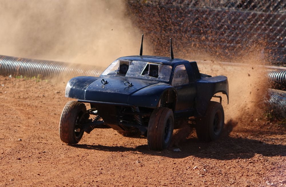
Very interesting research from Georgia Tech, using a RC truck running ROS and a Nvidia graphics board. From IEEE Spectrum:
Most autonomous vehicle control software is deliberately designed for well-constrained driving that's nice, calm, and under control. Not only is this a little bit boring, it's also potentially less safe: If your car autonomous vehicle has no experience driving aggressively, it won't know how to manage itself if something goes wrong.
At Georgia Tech, researchers are developing control algorithms that allow small-scale autonomous cars to power around dirt tracks at ludicrous speeds. They presented some this week at the 2016 IEEE International Conference on Robotics and Automation in Stockholm, Sweden. Using real-time onboard sensing and processing, the little cars maximize their speed while keeping themselves stable and under control. Mostly.
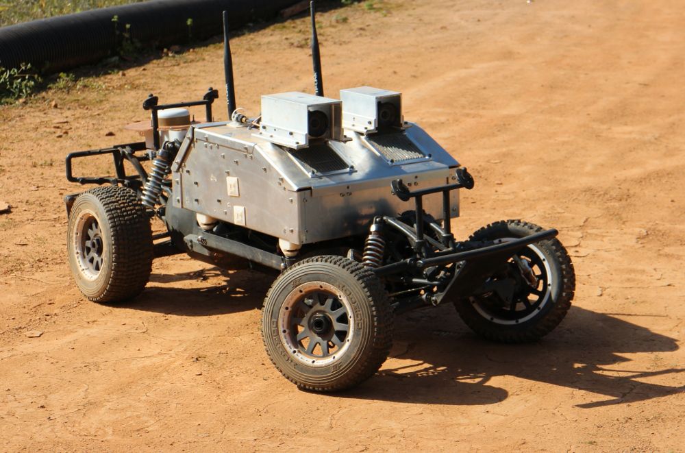
The electrically powered research platform pictured above, which is a scale model one-fifth the size of a vehicle meant for human occupants, is called AutoRally. It's about a meter long, weighs 21kg, and has a top speed of nearly 100 kilometers per hour. It's based on an R/C truck chassis, with some largely 3D-printed modifications to support a payload that includes a GPS, IMU, wheel encoders, a pair of fast video cameras, and a beefy quad-core i7 computer with a Nvidia GTX 750ti GPU and 32 gigs of RAM. All of this stuff is protected inside of an aluminum enclosure that makes crashing (even crashing badly) not that big of a deal.
To test out the hardware and software, AutoRally was unleashed on a dirt track at Georgia Tech and tasked with keeping its speed as close as possible to 8 meters per second while not crashing. The video [below] is a bit long; the racing starts at about 2 minutes in, with some impressive near-crashes (and actual crashes) from 5 minutes onward:
The real magic here is the algorithm that manages AutoRally’s steering and throttle. Rather than hierarchically splitting control and planning into two separate problems, Georgia Tech's algorithm combines them by integrating vehicle dynamics in real-time. Generally, this is a very computationally intensive approach, but AutoRally can calculate an optimized trajectory from the weighted average of 2,560 different trajectory possibilities, all simulated in parallel on to the monster onboard GPU. Each of these trajectories represents the oncoming 2.5 seconds of vehicle motion, and AutoRally recomputes this entire optimization process 60 times every second.
The initial training phase consists of just a few minutes of a non-expert human driving AutoRally around the track in remote-control mode; all of the fancy stuff (like the powersliding) is a product of the algorithm itself. Such aggressive driving is necessary when the speed of the vehicle exceeds its friction limit—a potentially dangerous condition for inexperienced robot drivers and human drivers alike. And this is why research into aggressive driving is not just fun but important. Just as expert human drivers can take advantage of how their vehicles handle at the very limits of control in order to drive fast yet safely in extremely challenging conditions, self-driving cars should be able to use the same techniques to avoid accidents in bad weather.
The researchers told us that most of the crashes in the video happened due to either software crashes (as opposed to failures of the algorithm itself), or the vehicle having trouble adapting to changes in the track surface. Since that video was made, they've upgraded the software to make it able to handle a more realistically dynamic environment. The result: AutoRally is now able to drive continuously on a track that, because of temperature changes, goes from, say, partially frozen to a huge puddle of mud over the course of a couple of hours.
They’ve placed all of AutoRally’s specs online (and made the software available on Github) in the hopes that other vehicle autonomy researchers will be able to take advantage of the platform’s robust, high-performance capabilities. The code is open source and ROS compatible, with an accompanying Gazebo-based simulation.
We're hoping that this algorithm will eventually be mature enough to be tried out on a full-size rally car (maybe in a little friendly competition with a human driver). But if that does ever happen, crashing will be a much bigger deal than it is now.
Aggressive Driving with Model Predictive Path Integral Control, by Grady Williams, Paul Drews, Brian Goldfain, James M. Rehg, and Evangelos A. Theodorou from the Georgia Institute of Technology, was presented this week at ICRA 2016 in Stockholm, Sweden.

How Harvard's Robobee nanodrone project is using the learning from real bees to improve the technology. Flexible wings that can handle collisions don't require as advanced sense-and-avoid skills.
Dronecode and the idea of open source UAV development is really taking off in China. Here's an example (Google translated from the original Chinese) of how sophisticated the understanding of the project already in. It's authored by at team at Unmanned Aircraft Design Institute, Beijing University of Aeronautics and Astronautics.
Very impressive!
Open source flight control development
Flight Control open source development can be divided into three generations:
The first generation of open source flight control system uses the open-source Arduino or other similar electronic platform, extended to connect a variety of MEMS sensors, allowing the UAV to fly rose steadily, its main feature is modularity and scalability.
The second-generation open source flight control system mostly has its own open-source hardware, environment and community development, the use of fully integrated hardware architecture, all 10DOF sensors, host microcontroller, or GPS and other equipment, all integrated in a circuit board, in order to improve reliability sex. It uses all-digital three-axis MEMS AHRS sensors (IMU); able to control the aircraft to complete autonomous flight routes, while the installation of radio communication with the ground station, initially with complete autopilot function. Such flight control can also support a variety of unmanned devices, including fixed-wing aircraft, multi-rotor aircraft, helicopters and vehicles, and have a variety of modes of flight, including flight manual, semi-autonomous and fully autonomous flight flight. The second-generation flight control of the main characteristics of high integration, high reliability, and its function has been close to the commercial autopilot standards.The third-generation flight control system will be open source innovation in software and artificial intelligence. It joined the cluster fly, image recognition, autonomous obstacle avoidance, automatic flight tracking and other advanced features flight to machine vision, clustering, development platform direction.
As the platform is gradually being accepted by the fans, electronic expansion modules endless variety of functions, which is the most complex integration of MEMS sensors flight controller. To get a better flight control design source code, Arduino company decided to open its flight control source code, they opened a path of development open source flight control. WMC-known open source flight control and flight control Arduino APM is a direct derivative products, still using the Arduino development environment for development.
APM Flight Control
APM (ArduPilotMega) in 2007 by the DIY UAV community (DIY Drones) Release fly control products, is the most mature open source hardware projects. APM Arduino open source platform based on hardware made many improvements, including accelerometers, gyroscopes and magnetometers combination of inertial measurement unit (IMU). Because APM good customizability, APM spread rapidly on a global model aircraft enthusiasts range open. Mission Planner by open-source software, developers can configure APM settings, accepts and displays sensor data, use google map complete autopilot and other functions, but the Mission Planner only supports windows operating system.
Currently APM flight control flight control has become a mature open source benchmark that can support multi-rotor, fixed wing, helicopters and unmanned aerial vehicles and other unmanned devices. For multi-rotor, APM Flight Control supports a variety of four, six, eight-axis products, and later be able to connect an external GPS sensor augmentation, and complete autonomous landing, autonomous airline flight home, set high, fixed and other rich flight mode. APM can connect an external optical flow sensor and ultrasonic sensors, indoor realize fixed and fixed-point flying high.
PX4 and PIXHawk
PX4 is a hardware and software open source project (to comply with BSD protocol), it aims to provide a low cost for the academic, hobby and industry groups, high-end autopilot. The project stems from the Zurich Federal Institute of Technology in Computer Vision and Geometry Lab, autonomous systems and laboratory automation laboratory PIXHawk project. PX4FMU autopilot module running efficient real-time operating system (RTOS), Nuttx provide Portable Operating System Interface (POSIX) type of environment. For example: printf (), pthreads, / dev / ttyS1, open (), write (), poll (), ioctl () and so on. Software can use USB bootloader update. PX4 through MAVLink same ground station communication, compatible ground stations have QGroundControl and Mission Planner, open source software and comply with all BSD agreement.
3DR APM Group and by the Joint PX4 group launched in 2014, is an upgraded version PIXHawk flight control flight control PX4, PX4 and APM has two sets of firmware and the corresponding ground station software. The Flight Control Flight Control is the world's top products in the hardware specifications of the product, but also the hottest product in the hands of enthusiasts present. PIXHawk has 168MHz operation frequency, and a breakthrough in the use of integrated hardware floating point core Cortex-M4 microcontroller as the main control chip, built-in gyroscope and two accelerometers MEMS sensors, complementary correction, built-in three-axis magnetic field sensor and you can add a three-axis magnetic field sensor, and can add a main one two GPS sensors, automatic switching in case of failure.
Core and floating-point arithmetic based on its high-speed operation, PIXHawk using the most advanced high-set algorithm, barometric altimeter alone can put aircraft at a fixed height within 1 meter. It supports almost all multi-rotor type, and even includes three rotor and H4 so irregularly structured products. It makes a variety of aircraft has flight mode, support for autonomous these key points around the mouse to guide, "FollowMe", to the end of the flight and other senior flight patterns, and the ability to complete independent parameter adjustment.
Openness PIXHawk flight control very well, hundreds of parameters are all open to the players to adjust, after relying on the basis of simple debug mode can fly. PIXHawk integrate multiple electronic map, fans can be selected according to local conditions.
OpenPilot and Taulabs
OpenPilot by OpenPilot community launched in 2009 autopilot project, designed to provide the community with low cost but powerful stable autopilot. The project consists of two parts, including OpenPilot autopilot and its supporting software. Wherein the portion of the firmware autopilot by the C language, and the ground station is written in C ++, and runs on Windows, Macintosh OSX and Linux three major operating systems.
OpenPilot most important feature is the hardware architecture is very simple, from which now has many hardware design can be seen its distinctive place. The official release of the flight control hardware includes CC, CC3D, ATOM, Revolution, Revolution nano, etc., derived hardware including Sparky, Quanton, REVOMINI, and even use the STM32 development board includes a direct extension from the FlyingF3, FlyingF4, DescoveryF4 etc., which have been CC3D the following is the preferred flight control 300mm wheelbase and ultra-small machines through the indoor model aircraft, which has been used extensively for lovers DiscoveryF4 flight control, Quanton is to become the first choice of hardware Taulabs.
Let's say Openpilot's most popular hardware CC3D it. This flight control panels using only a 72MHz 32-bit STM32 microcontroller and a MPU6000 be able to complete four-rotor, fixed wing, helicopter flight attitude control (note that the hardware can be of three degrees of freedom posture control, rather than increase stable), the board size is only 35mm × 35mm. As with all open source flight control, it does not require GPS or a magnetic field sensor fusion participate amendments can be maintained for a long time attitude control. All of the above functions all use a firmware by setting you can change the type of aircraft, flight mode, support PTZ augmentation and other functions. Whose compiled firmware required capacity of only about 100KB, code efficiency amazing, all flight control programmers learning model. Its ground station software integrates a complete electronic maps, real-time monitoring via radio condition of the aircraft.
TauLabs flight control flight control is OpenPilot derivatives. The most popular current TauLabs hardware is called Quanton, former OpenPilot flight control team members complete independence. It inherits OpenPilot simple and efficient features, and expanded barometric altimeter and triaxial magnetic field sensor, upgrade the master microcontroller Cortex-M4 core with hardware floating-point operations. The flight control parameter is the first open-source support auto flight control product, with the model identification algorithm, capable of self-tuning PID control parameters attitude in flight. TauLabs able to complete many advanced flight mode, after connecting an external GPS enables multi-rotor with fixed-height, fixed, home and other functions. Integrated flight control electronic map, and the interface is very friendly, wizard mode is initialized, beginners can easily get started.
MultiWiiCopter (MWC)
MultiWiiCopter (MWC) flight control is a typical Arduino derivative products, is designed for low-cost multi-rotor flight control development, it is to retain the integrity of the Arduino IDE Arduino development and use of methods and equipment upgrades. Due to the low cost, simple structure, the firmware is relatively mature, so the flight control has lots of fans at home and abroad. In addition to supporting the common four, six, eight rotor outside, the biggest feature of the flight control is to support a lot of strange type of aircraft, such as a triple rotor Avatar aircraft (BIcopter avatar style), Y4 multi-rotor (two-axis upper and lower opposed ), etc., so that the development of flight control interest is strong, easy to appreciate everyone's favorite.
KKMultiCopter
KK flight control is an open-source from Korea flight control projects, but also the first widely accepted multi-rotor flight control, flight control at the beginning of the open source development of the flight control, turned out for the entire industry is a four-rotor a shock. The flight control using only three low-cost single-axis gyro, with a simple four-channel remote control device, can control the common three, four, six rotorcraft, and support for "cross" type, X-type, H-type and vertically on opposite other layouts. The flight control using three adjustable resistance adjustment sensitivity as a parameter adjustment method, retained the earlier model aircraft gyroscope features. As a multi-rotor flight control an important witness for the initiation of this "antique" class classic flight control, still has many players.
Paparazzi (PPZ)
Paparazzi (PPZ) is a fully open-source hardware and software project, which began in 2003, the development goal is to establish a flexible configuration and powerful performance open source flight control project. PPZ is a major feature of the open-source flight control program in addition to the common flight control hardware, software and ground station flight control software, also includes a ground station hardware, including modems, antennas and other equipment. Functionally, PPZ is close to a small UAV system has.
Another feature of the project is to use ubuntu open source operating system, it will all ground station software and integrated development environment at the system, officially known as the Live CD. Plus a CD of flight control hardware can be completed all the work from development to use.
PPZ most popular hardware version of Paparazzi (PPZ) Lisa / M v2.0. The hardware has a large expansion interface, and using scalable single IMU sensor board. It is also open early flight control more popular approach, such as a desktop computer can be like DIY, with the escalation of IMU sensor upgrade hardware.
Autoquad ESC32 flight control and power transfer
Autoquad flight control from Germany, as an early open source flight control, Autoquad very powerful, but limited by the time of the sensors, it had to use a lot of analog MEMS sensors. The so-called analog sensor means is a sensor chip is not integrated digital to analog converter (ADC) and core operations, and direct micro-mechanical sensors will vary by hardware after amplification and filtering to form a voltage output and requires a master microcontroller AD acquisition. Because the sensor at different temperatures, the output value will be affected, analog MEMS sensor calibration parameters to a lot of trouble. Many players in the first use of the flight control, had to use the refrigerator for sensor calibration, and some manufacturers in order to ensure the stability of bulk products, only on the aircraft on board for heating to keep the temperature constant .
However, this calibration method but for some of the elite enthusiasts bring extra fun, but a lot of people this way. For most ordinary fans, this is really a work of no small difficulty. With the popularity of digital sensors with factory calibration, Autoquad as the accumulation of history, also completed its mission.
However, another branch of the open source project ESC32 ESC has gradually been accepted in the player. The ESC is the first use of a digital interface for controlling power transfer products, the player can control the motor speed through the serial port, I2C and CAN interface, than conventional PWM interface information many times faster. ESC common PWM waveform update rate of four hundred times per second, and the updated speed digital interface can reach millions. Especially for very sensitive to changes in the power of multi-rotor, this high-speed communication is necessary. The ESC also supports closed loop speed, and can be adjusted in detail for the motor parameters, these functions are the traditional model aircraft power transfer can not be compared.
Of course, Autoquad are making progress, it released a new flight control product Autoquad M4, on the host microcontroller and sensor of a comprehensive upgrade, using common STM32F4 microcontrollers and digital sensors. But the face of PIXHawk, APM and other mature advanced flight control products for many years, it has been reduced from predecessors comer.
5 must know the MEMS sensor
Why MEMS
Finished open source flight control, we need further research on the key device --MEMS flight control sensor on. If compared to the aircraft autopilot "brain", the MEMS sensor is the "vehicle" of the ear, nose and eyes. It is these sensors will collect dynamic information of the aircraft and sent to the host microcontroller, the aircraft will be able to get the attitude and position of the aircraft by calculation.
Why open source flight control to use MEMS sensors? To develop flight control, how to get the aircraft AHRS is the first task, the traditional manned aircraft generally use mechanical gyros and fiber optic gyros to accomplish this task, but is limited by size, weight and cost, and other small multi-rotor aircraft in on can not use this equipment. Therefore, the MEMS sensor at the core of DOF (Degree Of Freedom, freedom) system has become the only option. Since the past decade, the rapid development of mobile phones and game consoles, making the MEMS sensor in the last ten years has been the rapid popularity, so that low-cost motion perception as possible, which is currently the flight control system formed by micro Basic conditions.
MEMS sensors and mobile phones and game consoles are using open-source flight control from the same manufacturers, such as ST microelectronics, INVENSENSE like. MEMS sensor from the early multi-chip combination, the current development of single-chip integrated multi-axis sensors, sensor development from analog to digital sensors, has undergone a number of larger changes.
MPU6000
MPU6000 is the king of open source flight control sensor, although the new sensor endless, but has been unable to shake its status. PIXHawk flight control earlier version had abandoned MPU6000, but later had to be used because Fengyun MEMS chip has been performed for all lovers of open source flight control project development acceptable.
MPU6000 in a 4mm × 4mm chip integrates a three-axis angular rate gyro and three-axis accelerometer and integrated AD acquisition, core solver, and a temperature sensor. This high degree of integration was still unmatched by other vendors. As for the rotation matrix, quaternion output and fusion algorithms Euler angles format of the data is reduced to a host microcontroller to calculate the amount of attitude solver. SPI and I2C dual digital interface, 3.3V same with most microcontroller supply voltage (2.4V to 3.4V), 4mA maximum power consumption, customizable sensor range, -40 ℃ to + 85 ℃ operating temperature of these ...... feature greatly facilitates the work of the host computer. No wonder INVENSENSE confidently say that this product is MPU (Motion Processor Unit, motion processing unit), and without any suffix behind chip models.
All want depth development of open source flight control fans should begin to learn basic algorithm solver and AHRS sensor from the chip, which is the most simple and effective way. OpenPilot of CC3D flight control gave you provide a good example, only use a sensor of this, they made a classic flight control products.
MS5611
MS5611 is another legend sensor. Chip size of only 3mm × 5mm, the sensor accuracy is better than a lot of professional aviation equipment, and the price is very cheap. The sensor MEAS launched by the Swiss company, before this, most of the flight control uses a Motorola pressure sensor, volume is several times larger, and not chip devices need to "stand" on the circuit board, MS5611 once launched immediately All flight control becomes open source pressure measurement standard.MS5611 sensor response time of just 1ms, work consumes 1μA, can measure the pressure value 10-1200mbar. MS5611 with SPI and I2C bus interface, and MCU same supply voltage, -40 ℃ to + 85 ℃ operating temperature, SMD package, fully shielded metal housing, integrated 24 high-precision AD acquisition and other features that make it is very suitable for work in a highly integrated digital circuits, it has become a source of pressure altitude flight control test of choice.
HMC5883
Contact magnetoresistive sensor (that is, magnetic compass sensor) knows, the Z-axis magnetoresistive sensor is flat realize how not easy. Honeywell also developed in dozens of related products after finally have the ability to produce this fully integrated three-axis digital compass. We had to marvel at its size -3mm × 3mm in size, thickness of less than 1mm. Even more amazing is its low price, so in addition to this extreme pursuit PIXHawk Advanced flight control hardware, other open-source flight control, if equipped with a magnetic compass, then invariably use the HMC5883. Of course, Honeywell has already launched an upgraded model of HMC5983, will increase the angle measurement accuracy to within 1 °. For fans who, HMC5883 has been good enough.Design difficulties magnetoresistive sensor is demagnetized ferrite, ferrite sensors and able to drive degaussing unit, 12-bit ADC, integrated computing cores and all in such a small chip which is a very difficult. HMC5883 Other features include: achieving 2mGS resolution of ± 8GS magnetic field, with the same single-chip supply voltage, -30 ℃ to + 85 ℃ working environment temperature. Although ST microelectronics has launched an integrated three-axis magnetoresistive sensor and a triaxial accelerometer LSM303D, and smaller, more integrated, but it has been the preferred chip HMC5883 magnetic compass.
L3GD20
L3GD20 area just 4mm × 4mm, which is destined for mobile devices and health. ST is the first batch of development of MEMS chip manufacturers, but also the first release gyro products company, but L3GD20 still a step late. Although it higher precision, but the limelight has been snatched away MPU6000. Although there is no integrated three-axis accelerometer, but with high-precision angular rate measurements, a wide range of custom range, and lower prices, L3GD20 gradually the industry admit that PIXHawk once wanted to use it to replace MPU6000. Of course, eventually did not materialize PIXHawk alternative aspirations, they co-exist on top of the open-source flight control, complement each other, the achievements of the redundant design PIXHawk.
L3GD20 with the same single-chip supply voltage, ambient temperature -40 ℃ to + 85 ℃, and is compatible with I2C and SPI digital interface, built-in down / high-pass filter circuit, 6mA operating power and integrated temperature sensor, these same integrated circuit can be used as a high angular rate gyroscope good choice.
LSM303D
If other sensors for mobile devices is born, it is to L3GD20 LSM303D born. It L3GD20 together can form a complete 9DOF AHRS sensor system (IMU), and its power supply, measurement accuracy and digital interface is almost identical. The system than MPU6000 combination HMC5883 and lower total cost, higher measurement accuracy, no wonder INVENSENSE to launch non-stop series of single-chip 9DOF MPU9250 products to compete.And MCU same supply voltage, ambient temperature -40 ℃ to + 85 ℃, and is compatible with I2C and SPI digital interface, integrated temperature sensor, these parameters can be copied almost L3GD20.
6 How software controls hardware
Finished hardware, let's talk about common algorithms. Open Source flight control architectures, the software is also very different. But as long as the flight control are inseparable SINS, Kalman filtering and PID control these three algorithms.
SINS system
Navigation purpose is to obtain real-time UAV attitude, velocity and position parameters. Photoelectric encoder can be used to measure the rotation angle of the UAV, the UAV speed motor used to measure angular velocity, tachometer used to measure the speed of the UAV, but above all the various measurements alone can not simultaneously measure UAV line motion and angular motion, inertial navigation can do this. Because the inertial navigation system does not require a physical reference, so it is called the system DOF (Degree Of Freedom, freedom), in addition to external inertial navigation will not interfere with the natural and man-made device, particularly suitable for use in harsh environments.
After the 1990s, with the development of micro-electromechanical systems (MEMS) technology, inertial sensor to achieve a volume of miniaturization, improved reliability, and suitable for mass production, from the strapdown inertial navigation system into the MEMS field, and began to civilian areas and widespread penetration appears in a new generation of robotic systems and a vehicle. In the 21st century, SINS system is almost completely replaced the Platform Inertial Navigation System.
Kalman filter algorithm
Signal transmission and detection process will inevitably be affected by interference from outside noise inside the device, in order to get an accurate signal, it is necessary to filter the signal. The so-called filter means to extract from many signals are mixed together in a useful signal process. For example, the well-known low-pass filter is the use of different frequency bands in which the signal is provided with a corresponding frequency characteristics of the filter, so that useful low-frequency signal as far as possible without attenuation through, so as to remove high frequency noise.
The Kalman filter is extracted from observations with the signals associated Kalman proposed in 1960, estimated by the algorithm filtering algorithm of the desired signal, his innovative concept introduced in state space stochastic estimation theory, the signaling process to see for linear input - output processes with white noise, the use of the system in the estimation process multiple equations constitute filtering algorithm. Moreover, Kalman filter input and output by time and observation update update algorithm linked, according to the system state equation and observation equation to estimate the signal processing required. So why Kalman filter is applied to the inertial navigation system as well? This is mainly because the "pure inertia" sensor inertial navigation system is not sufficient to achieve the required navigation accuracy, to compensate for the lack of navigation systems often use other navigation equipment to improve navigation accuracy to reduce the navigation error. So developers thought of Kalman filtering algorithm, using this algorithm, the data from the inertial navigation system and other navigation devices (such as inertial navigation system calculates the position of the GPS receiver position information control given) mixed use, estimates and correction unknown inertial navigation system error.
Flight Control PID algorithm
While improving the development of modern control theory, we get a lot of people through scientific research and theoretical algorithm has excellent control effect, but in engineering applications, based on the classic PID control algorithm is still the easiest and most effective control program. The current mainstream in several open source flight control, without exception, are based on the PID control algorithm to achieve UAV attitude control and trajectory.
PID controller is a linear controller, which is mainly based on the given value and the actual output values constitute a control deviation, and then use the deviation is given a reasonable amount of control.
Then the PID controller algorithm can solve the problem? In multi-rotor, for example, in the absence of the control system, the signal is directly driven propeller drive motor rotation control, there will be too fast dynamic response, or too slow, or control overshoot or shortage, multi-rotor can not the successful completion of take-off and hover action. To solve these problems, it is necessary to add the PID controller algorithm in the control system loop. Build relationships proportional, integral and differential between the attitude information and propeller speed by adjusting the parameters of the size of each link, so that multi-rotor control system to achieve fast dynamic response, but neither red nor lacking phenomenon.
Source: Journal of Industrial Robots
Unmanned Aircraft Design and Research Institute, associate professor of Beijing University of Aeronautics and Astronautics Li Dawei
Unmanned Aircraft Design Institute, Beijing University of Aeronautics and Astronautics engineer Yang Jiong
From Motherboard:
As drones are becoming more commonplace in cities, so are drone accidents. People are crashing their brand new toys and flying them places they shouldn’t be like crazy. Part of this is thanks to the complex wind environments in built-up areas, which can make drones go out of control. In the latest episode of Lab Spaces, Motherboard's Jordan Pearson visits WINDEEE, the world’s first hexagonal wind testing chamber where scientists are pushing drones to their limits in order to learn how to make drones safer in the future.
Boeing's Insitu division has released a ground control system that supports Solo, Iris+ and other ArduCopter based drones. University of Nevada is now using it.
Unmanned Vehicle Plug-in for Arducopter: Powerful command and control meets unmanned multicopter technology.
Search Plug-in: Time is paramount in every search mission and Inexa Control’s search plug-in helps operators plan and execute a fast, thorough search of an area using nationally recognized search patterns.
RF Link Analysis Plug-in: Terrain variation and other conditions can interfere with the transmission of information, but Inexa Control’s RF Link Analysis Plug-in helps operators identify in advance where communications could be potentially compromised.
Airspace Management Plug-in: Using an aircraft’s trajectory, vehicle information, and telemetry, Inexa Control’s Airspace Management Plug-in alerts operators of potential airspace violations by considering available airspace options and recognizing areas to avoid.
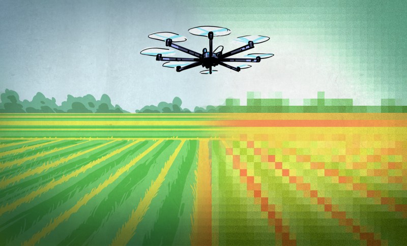
Good piece in Hackaday on how drones can revolutionize agriculture. Here's the start, but read here for the rest, including a deeper discussion on NDVI techniques.
Whether you call them UAVs (Unmanned Aerial Vehicles), UAS (Unmanned Aerial System), Drones, or something less polite – people are more familiar than ever with them. We’ll call them drones, and we’re not talking about the remote-controlled toy kind – we’re talking about the flying robot kind. They have sensors (GPS and more), can be given a Flight Plan (instructions on where to go), and can follow that plan autonomously while carrying out other instructions – no human pilot required. Many high-end tractors are already in service with this kind of automation and we’ve even seen automated harvesting assistance. But flying drones are small and they don’t plant seeds or pull weeds, so what exactly do they have to do with agriculture?
There are certain things that drones are very good at, and there are things in agriculture that are important but troublesome to do or get. Some of these things overlap, and in those spaces is where a budding industry has arisen.
Let’s cover what drones can offer and what growers can use, then dig into what is out there and happening over some fields right now.
These Things are Important to Farmers, but are Limited or Troublesome
Confirmation: Verifying that plants are growing where and when they should, and checking this as early and often as possible.
Early Detection of Problems: Detecting areas of poor growth and crop damage as early as possible, limiting impact and maximizing the chances of doing something about it.
Fertilizer Planning: A crop will never grow completely evenly, and choosing where to put fertilizer and how much to use based on plant density and health (instead of spreading it uniformly) can save significant money. This is called Variable Rate Application and anything that helps it get done more accurately saves money and increases crop yield.

From the blog of the Pixahwk-compatible high-accuracy Reach RTK GPS
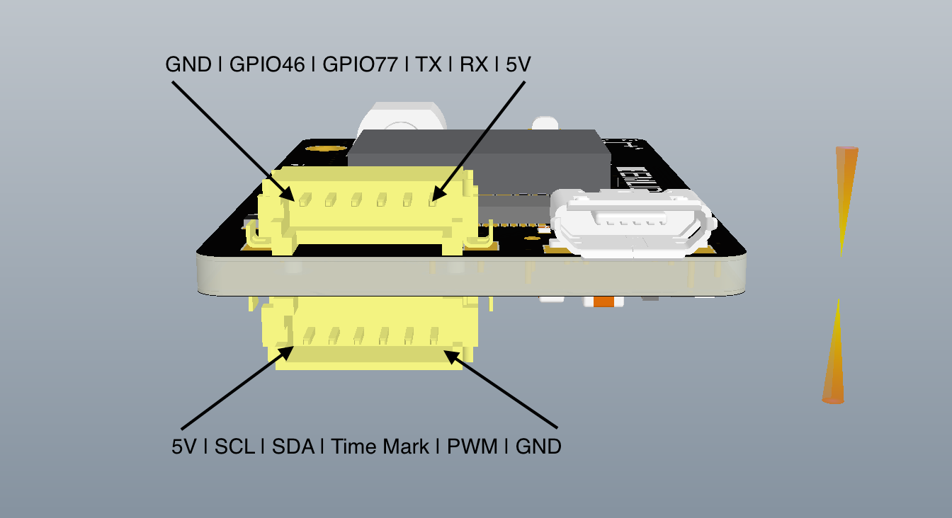
Reach was built with precision mapping applications it mind. One of the big challenges in UAV mapping is eliminating Ground Control Points which are time consuming and costly to place. Reach RTK can help achieve that by synchronizing with the camera shutter on sub ms level. I have written more about this in a previous post. All you need to do is connect hotshoe adapter to your camera and wire it to Reach port. Only two connections are required "GND" and "Time Mark":

At top is how @timvand did it with his Sony A6000.
During RINEX conversion on Reach you will see a new field that will show how many time marks have been collected. That should match the amount of pictures taken by the camera.
Those of you who have access to GrafNav can already start mapping and getting accurately georeferenced pictures. Thanks to @Stu74 we know that it parses time marks from RINEX and interpolates the post processed coordinates.
We have also implemented this feature in RTKLIB and will release modified RTKPost soon.
As usual new amazing features are brought to you by @efedorov's and @bulatov's countless hours of work
Emlid is going to make right what is broken about UAV mapping.
This is a really important problem to solve; hope someone does! From Popular Mechanics:
An engineering firm wants to make sense of the abundance of aerial photos we now shoot from planes, satellites, and drones. Draper, out of Massachusetts, has put a $40,000 bounty on an algorithm that can accurately sort and sequence images taken from miles in the sky, with implications, perhaps, to track wildlife, observe erosion, direct traffic, or notice climate change in real time.
The contest, which runs until June 27, requires the algorithms to take a series of images taken of California and correctly sequence them in the order they occured. The hope is that subtle changes can then be noticed (simple enough) and also understood (much trickier).
It might be years before we could understand all the data that correctly sequenced images can convey, but global security operations have been doing similar things for the past 80 years. As the world swims in ever more photos, we could stand to gain a lot by being able to automatically interpret them. The right algorithm could have wide-ranging effects for scientists, corporations, governments, and hobbyists alike.
New parachute for Solo released from Parazero. From Ars Technica:
To ensure that the parachute deploys in time to prevent a crash at low altitudes, SafeAir shoots out the chute with a gust of pressurized gas. SafeAir attaches to the top of a drone and uses an independently powered chip to detect when the drone goes into freefall. According to a company spokesperson, SafeAir has worked with drone manufacturers to develop recovery systems for their drones based on how far it is safe for their drones to fall—including DJI (the makers of the popular Phantom consumer drone), professional photography drone maker 3D Robotics, and Martin Aviation—makers of the JetPack search and rescue small uncrewed aerial system (UAS).