A new system from MIT’s Computer Science and Artificial Intelligence Laboratory (CSAIL) is the first to allow users to design, simulate, and build their own custom drone. Users can change the size, shape, and structure of their drone based on the specific needs they have for payload, cost, flight time, battery usage, and other factors.
To demonstrate, researchers created a range of unusual-looking drones, including a five-rotor “pentacopter” and a rabbit-shaped “bunnycopter” with propellers of different sizes and rotors of different heights.
“This system opens up new possibilities for how drones look and function,” says MIT Professor Wojciech Matusik, who oversaw the project in CSAIL’s Computational Fabrication Group. “It’s no longer a one-size-fits-all approach for people who want to make and use drones for particular purposes.”
The interface lets users design drones with different propellers, rotors, and rods. It also provides guarantees that the drones it fabricates can take off, hover and land — which is no simple task considering the intricate technical trade-offs associated with drone weight, shape, and control.
“For example, adding more rotors generally lets you carry more weight, but you also need to think about how to balance the drone to make sure it doesn’t tip,” says PhD student Tao Du, who was first author on a related paper about the system. “Irregularly-shaped drones are very difficult to stabilize, which means that they require establishing very complex control parameters.”
Du and Matusik co-authored a paper with PhD student Adriana Schulz, postdoc Bo Zhu, and Assistant Professor Bernd Bickel of IST Austria. It will be presented next week at the annual SIGGRAPH Asia conference in Macao, China.
Today’s commercial drones only come in a small range of options, typically with an even number of rotors and upward-facing propellers. But there are many emerging use cases for other kinds of drones. For example, having an odd number of rotors might create a clearer view for a drone’s camera, or allow the drone to carry objects with unusual shapes.
Designing these less conventional drones, however, often requires expertise in multiple disciplines, including control systems, fabrication, and electronics.
“Developing multicopters like these that are actually flyable involves a lot of trial-and-error, tweaking the balance between all the propellers and rotors,” says Du. “It would be more or less impossible for an amateur user, especially one without any computer-science background.”
But the CSAIL group’s new system makes the process much easier. Users design drones by choosing from a database of parts and specifying their needs for things like payload, cost, and battery usage. The system computes the sizes of design elements like rod lengths and motor angles, and looks at metrics such as torque and thrust to determine whether the design will actually work. It also uses an “LQR controller” that takes information about a drone’s characteristics and surroundings to optimize its flight plan.
One of the project’s core challenges stemmed from the fact that a drone’s shape and structure (its “geometry”) is usually strongly tied to how it has been programmed to move (its “control”). To overcome this, researchers used what’s called an “alternating direction method,” which means that they reduced the number of variables by fixing some of them and optimizing the rest. This allowed the team to decouple the variables of geometry and control in a way that optimizes the drone’s performance.
“Once you decouple these variables, you turn a very complicated optimization problem into two easy sub-problems that we already have techniques for solving,” says Du. He envisions future versions of the system that could proactively give design suggestions, like recommending where a rotor should go to accommodate a desired payload.
“This is the first system in which users can interactively design a drone that incorporates both geometry and control,” says Nobuyuki Umetani, a research scientist at Autodesk, Inc., who was not involved in the paper. “This is very exciting work that has the potential to change the way people design.”
The project was supported, in part, by the National Science Foundation, the Air Force Research Laboratory and the European Union’s Horizon 2020 research and innovation program.
 Love
Love  Hyper spectral cameras scan the ocean’s surface and record 322 color wavelengths that can link to different biochemical processes in seawater.
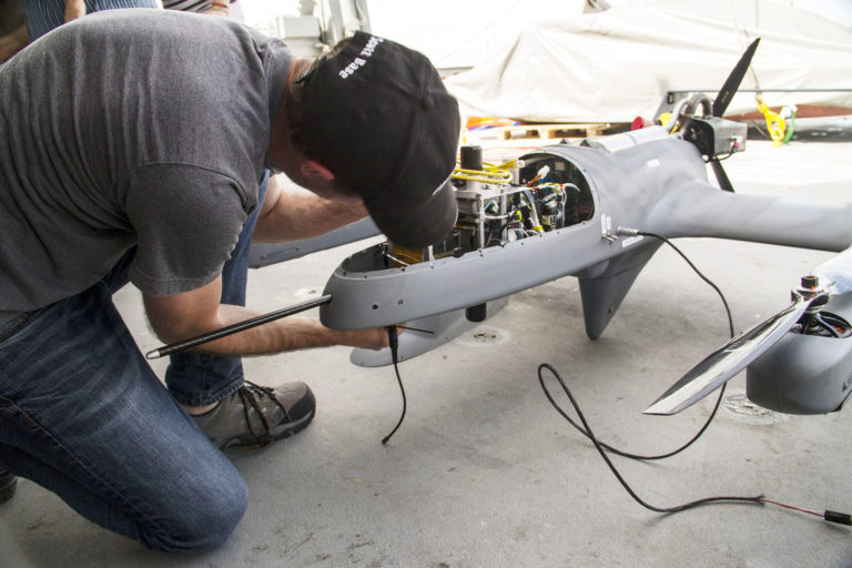
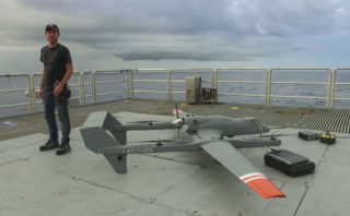 Scott Brown, Physicist and Engineer, stands next to one of the HQ-60B drones to scan the sea surface. The drone had just completed another successful mission and was being disarmed on Falkor’s flight deck.
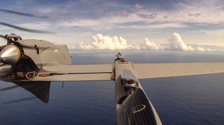 An HQ-60B drone flies over the Pacific Ocean, away from the effects that Falkor or clouds could have over data being collected. The aircraft flies an average of two hours in each mission carrying a payload of radiation, hyperspectral or infrared cameras.