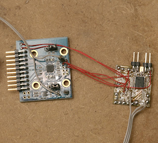
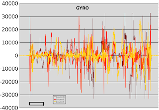
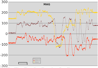
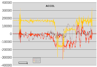
After another heroicly wasted day, the MPU9150 finally surrendered all 9 of its data streams. It has so many problems as a 1st run product, a much improved revision negating all of today's work is guaranteed. But with 2 MPU9150's lying around & a definite use, it was time to bang out a workaround just to get the data from it. The DMP firmware isn't going to happen.
Step 1: the 1st I2C command must be to set PWR_MGMT_1 (0x6b) to 0x01 to move it out of sleep mode & set the clock to the gyro oscillator. That puts 1.8V on the REG_OUT pin & 25V on the CPOUT pin. Nothing else works if it isn't the 1st command.
Step 2: set the remaining configuration registers after PWR_MGMT_1
0x37 = 0 // disable i2c passthrough
0x6a = 0 // disable i2c master
0x1b = 0 // gyro config
0x1c = 0 // accel config
0x19 = 0 // desired sample rate divider
The I2C passthrough didn't work. Only using dual I2C busses connected to the mane I2C & the aux I2C worked. The mane I2C reads the gyro & accel. The aux I2C reads the mag.
The real problem is if you simply read the gyro & accel registers, you'll always get the same value. They tried & failed to synchronize the register refreshes with inactivity on the I2C bus.
The only way to get the registers to refresh is to issue a bogus command to the mag on the mane I2C bus. I chose to read the mag status register (0x02) 1st on the mane bus to get the gyro/accel registers to refresh, then read the same mag register on the aux I2C bus to get the real value. It probably counts an unrecognized address as inactivity on the bus.
No amount of hacking could get the registers to update with passthrough enabled. It seemed to consider all communication with passthrough enabled as activity on the bus.
The aux I2C has decent enough pullups to read the mag at a decent rate. The mane I2C needs 1k pullups. It showed no obvious sensitivity to voltage changes between 2.5V & 3V. Its 1.8V regulator must make it immune to supply voltage fluctuations.
Hopefully that helps all the people with jobs involving the MPU9150 pay some of their medicare tax increases.
There's obviously some intended use involving the FIFOs, the myriad of slave registers, & the DMP instead of banging on the aux I2C manually, but any source code revealing how to do it is a closely guarded secret. The Apple model of a basic & premium developer program seems to have caught on at Invensense.


Comments
I just succeeded in getting the Mag values via the Pass-Through Aux method. It was rather frustrating figuring it out.
First thing I did was Read the Registers I was setting to Verify the device was getting my commands. Seeing that I was setting values on the chip, I could see that Pass-Through Mode was in fact ON.
Then the trick was to set the AK8975's CTRL ($0A) = %00000001 = Single Measurement Mode. This took it out of "sleep" mode and instantly gave results.
Here is my Config settings:
Write_Register(PWR_MGMT_1, %00000001) ' 107 - PWR_MGMT_1
Write_Register(SMPLRT_DIV, %00000001) ' 25 - SMPLRT_DIV = 1 => 1khz/(1+1) = 500hz sample rate
Write_Register(CONFIG, %00000100) ' 26 - Set DLPF_CONFIG to 4 for 20Hz bandwidth
Write_Register(Gyro_Config, %00011000) ' 27 - Gyro_Config
Write_Register(Accel_Config, %00010000) ' 28 - Accel_Config
Write_Register(User_Ctrl, %00000000) ' 106 - Disable Master Mode
Write_Register(INT_Pin_Cfg, %00110010) ' 55 - INT_Pin_Cfg
Write_Register(INT_Enable, %00000001) ' 56 - INT_Enable
While trying to get a MPU9150 working I stumbled on this page and found the opening comment about a heroicly wasted day hit a little too close to the mark.
If I had seen this before I designed and built my PCB I might have added a connection to the auxilary I2C bus but I didn't. So I had a go at configuring the MPU9150 slave controllers with some success.
The sample rate is set to 50SPS because the magnetometer is pretty slow. Slave 0 is setup to read the status and data registers and Slave 1 is set to write the control register to trigger the next conversion. With that done, I just read a big chunk of data that includes everything with each data ready interrupt.
The slave config code:
I2Cwrite(MPU_ADDRESS, 4, "\x25\x8c\1\x89"); // slave 0 setup
I2Cwrite(MPU_ADDRESS, 4, "\x28\xc\xa\x81"); // slave 1 setup
I2Cwrite(MPU_ADDRESS, 2, "\x64\1"); // slave 1 data out
I2Cwrite(MPU_ADDRESS, 2, "\x24\x48"); // wait for slave data
I2Cwrite(MPU_ADDRESS, 2, "\x6a\x20"); // enable I2C master
(Note that the register address is the first byte of the data string.)
yeah
What part of the code do you need this is for read a register on the chip?
void i2cinit()
{
TWIF.MASTER.BAUD = 35; //32000000/(2(5(35)))=400000
//TWIF.MASTER.CTRLB = TWI_MASTER_SMEN_bm;//+TWI_MASTER_QCEN_bm;
TWIF.MASTER.CTRLA = TWI_MASTER_ENABLE_bm;
TWIF.MASTER.STATUS = TWI_MASTER_BUSSTATE_IDLE_gc;
}
uint8_t i2cRead(uint8_t address){
uint8_t i=0;
TWIF_MASTER_ADDR = write_addr; //tell device we're writing to it
while(WIF == 0); //wait for device to ack
TWIF_MASTER_DATA = address; //tell device we want to read from output
while(WIF==0); //wait for device to ack
TWIF_MASTER_ADDR = read_addr; //send read addr to device
while((WIF == 0) && (RIF == 0)); //wait for ack
i = TWIF_MASTER_DATA; //fetch data
TWIF_MASTER_CTRLC |= 0x04; //send nack
TWIF_MASTER_CTRLC |= 0x03; //send stop
return i;
}
I still have the problem with the magnometer
Can I have your code? still have problem with magnetometer.
I finally got the i2c working on a Xmega128a1U but I am trying to understand how I can read all 9 value at the same time? By same time I mean that the values were all clocked in from the ADC's at the same time. So I don't want values for another time interval. I will be reading the sensor data one right after another.ax->ay->az->gx->gy->gz->mx->my->mz(unless there is a better way please point out my errors)
*main
how to get DMP from 9150 with i2c ? Register map is not include these details..
ja,
relaxed waiting is the key for success with that strange company.
maybe we see a crippled/stripped down version which omits some parts.
if we see a 3300A or B Variant then we know what happened...
-
1
-
2
of 2 Next