All Posts (14065)

Sort by

Building a UAV for photo mapping - Kit Mods


First I must thank Jeffrey Johnson who posted a set of images of the Cularis he is building for photo mapping. He has made a really neatmodification by moving the rudder and elevator servos from the stockposition in the cockpit, to tail mounting in the fuselage. Not onlydoes this free up space in the cockpit area, which will make it easierto enlarge to take the camera, but it also moves some 35gm of weightto the rear. This should greatly help in balancing the plane withoutadding too much lead.


I have also now read some 670 posts in the Cularis building thread on the rcgroups forum. There is a wealth of good stuff there, includinga number of modifications to the stock kit to improve performance and ease of use. Specifically, I now plan to do the following.


  • Extend the travel of the flaps by reversing the control horns, thus allowing for slower landings
  • Reverse the direction of one of the flap servos so that if can be connected to the other flap servo with a simple Y lead.
  • Remove some 30% of the hinge material from the ailerons and flaps to reduce the load on the wing servos.
  • Cut away the stock mountings for the mating connectors in the wing roots and run the cables through to connect by hand. This seems to be amajor cause of poor reliability as if the wing moves a little inflight, the connectors can cease to make contact, leading to loss ofcontrol in the wing.
  • Replace the side canopy latches with a single magnetic mount on the rear bulkhead. This also makes it easier to enlarge the cockpit area totake the camera.
  • Move the servos for rudder and elevator to the rear.
  • Sand the trailing edges of the rear stabilizers a little to reduce drag.


There is one other modification that I am in two minds about and that is a secondary means of fixing the wings. In the stock kit, the wings areheld in place with plastic catches. These are design to open in theevent of a heavy landing so that the wings break away. If wouldseem, however, that some have opened in flight leading to spectacularcrashes. Jeffrey has a a similar modification to several shown inthe thread that involve using a secondary pin through the wing root.While this will certainly keep the wings solidly in place, I am notsure if it is better or worse in the case of a bad landing.


Building a UAV for phot mapping - Previous Posts


  1. The Goal
  2. Camera Selection
  3. Packing it all in
  4. Autopilot
  5. Kit Mods


Read more…

Building a UAV for photo mapping - Autopilot


Ahh!! CRASH and BURN!!


I had planned to use the Pico-Pilot and Pico-GPS for the autopilot in my UAV, but I have now discovered that since Jan 2007, they have been classed as MILITARY technology and are controlled by US Export License regulations. Specifically theregulations cover,


a. “UAVs” having any of the following:

a.1. An autonomous flight control and navigation capability (e.g., an autopilot with an Inertial

Navigation System); or

a.2. Capability of controlled flight out of the direct visual range involving a human operator

(e.g., televisual remote control).

b. Associated systems, equipment and components as follows:

b.1. Equipment specially designed for remotely controlling the “UAVs” controlled by 9A012.a.;

b.2. Guidance or control systems, other than those controlled in Category 7, specially designed for

integration into “UAVs” controlled by 9A012.a.;

b.3. Equipment and components specially designed to convert a manned “aircraft” to a “UAV”

controlled by 9A012.a.


Note: 9A012 does not control model aircraft.


Despite the last sentence, UNAV, who make the Pico Pilot have now told me that none of the applications for export licenses they have made thisyear have yet been granted. Back to the drawing board.


The other common low cost option for an autopilot seems to be based on the FMA Co-Pilot for flight stability with an additional board suchas the RCAP2 plus a GPS receiver for navigation. While a cheaperalternative, I had already discounted this approach because it isbased on thermopile sensors. For my terrain, I cannot get a clear360degree view of the horizon to calibrate the system before launch.In addition, the various different terrain types , forest, grassland,lakes etc. could give problems in flight, irrespective of thetemperature differences that can occur if different parts of a valleyare in sunlight or shade.


During my initial research into autopilots, I also looked at the Paparazzi project. While there is a wealth of open source stuff there, thecurrent Tiny autopilot still uses thermopile sensors for stability,although it does have an on board GPS unit for navigation. An all singing, dancing IMU with gyro's , mangetometers etc. is under development. Althoughall the designs are published, there is still no commercial source ofassembled units or PCB's.


A recent post on this forum (can't find it now), talked about the the UAV development board from Sparkfun. I had a brief look at this, butinitially discounted as they claim that the firmware is a guidelineonly. It is also written in assembly code and I am far to old tostart writing in assembler again. Still I shall have another look atthis over Christmas, as the board does have a proper IMU with 2 gyrosand a 3 axis accelerometer.


Conclusions and Questions

  1. I cannot use my prefered autopilot option owing to US export regulations.
  2. What other, non US manufactured, commercial autopilots are people using?
  3. Any other suggestions for a home built unit with an IMU rather than thermopiles?


Building a UAV for phot mapping - Previous Posts

  1. The Goal
  2. Camera Selection
  3. Packing it all in
  4. Autopilot
Read more…
3D Robotics
What do you get for the hundreds of thousands or millions of dollars cost difference between our UAVs and those of the pros? Well, a lot (even after you take out defense contractor markups). Ours are one-offs that need a lot of hand tweaking, care and knowledge to use. They have limited range and altitude, and as we know all too well, sometimes they don't work at all. (But hey, losing a $1,000 UAV doesn't hurt as much as losing a $10 million one!)

In addition, they have only a small fraction of a pro UAV's feature set. I was reminded of this as I was looking at the source code for the Micronav software for the Crossbow hardware (shown), which one of the more sophisticated open source autopilot programs (but is still at the bottom end of the pro autopilot range).

Here are some of the things the Micronav software code has that we don't:

--Full avionics and telemetry data downlinked to the ground.
--A proper custom inertial measurement unit (IMU), using gyros and accelerometers and Kalman filters in software
--Data logging
--Smart ("look ahead") waypoint finding algorithms, that don't just get to a point but get to it efficiently and along a predictable line.
--Corrections for what part of the Earth you're flying over (northern or southern hemisphere).
--Use standard UAV commands for dynamic mission/waypoint changes, such as "loitering" over a target.
--Ground station software

Other autopilots have such features as:

--Automatic adaptation to different airframe platforms after inputting a pre-recorded flight from that aircraft.
--Auto-land and take-off
--Communications between camera and autopilot so you can steer the camera and let the plane steer itself
--Etc...

We'll get some of those feautures someday in our own UAVs, but for now we take all sorts of shortcuts to stay within the reach of amateurs. For instance, we usually don't build our own IMUs. The DIY Drones approach is to let some off-the-shelf hardware handle the tricky job of stabilization and our custom hardware and software just handles the easier 2D job of GPS navigation. We don't have any ground station software for real-time control and communications (just software for post-processing of imagery). You've got to hand-tweak the autopilots for each new airframe. And we let commercial GPS receivers handle the job of data logging.

Anyway, if you want to be reminded of how much math you've forgotten since college, check out the source code. And then be thankful for all we've spared you!
Read more…


The first image shows the recommended distribution of components for the electric version of the Cularis. (Click for higher resolution). In this configuration, the plane balances at the CGO with 3 weights (supplied in the kit) fixed under the tail plane. The component weight budget is


  • Motor/Prop Assemply 225gm
  • Multiplex ESC 34gm
  • Fight Battery 149gm
  • 7Ch Rx 30gm
  • Rx Battery 112gm
  • Cularis cable set 50gm
  • 6 servos 70gm


This gives a total of 670gm. The manufactures claim an all up weight of 1680gm with a wing loading of 30.5g/dm2.


In this image, I have added the Pentax A30 camera and a PicoPilot with PicoGPS. The camera is about 8mm wider than the center opening in the fuselage, so I will have cut back the sides for it to fit. I will also machine out a stepped hole in the base for the extended lens to sit in and see through. If I try to locate the camera further back, then I will have to machine out the two servo openings as well.


The addional weight is


  • Pentax A30 with battery and SD Card 150gm
  • Pico Pilot and GPS 63gm

However, I think the real problem is not the weight but the COG. A simplified calculation of the moments of the camera, the autopilot and the new position of the Tx about the COG, suggest that I will have to add about 70gm to the tail in order to bring the plane back into balance. So the total additional weight will be in the order of 283gm. This will increase the all up weight to 1963gm with a 16% increase in wing loading to 35.6g/dm2.


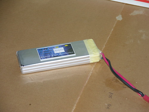
Although it may be standard practice, I am not really happy about have separate Fight and RX batteries. There are two things to charge and check before each flight and it just seems more elegant to have a single power source with a switch mode SportsBEC. With some searching, I found a DuraMax UltraPro 3s 3600mA Li-po with a flat form factor. The dimensions are 145mm x 50mm x 16.2mm. With a small amount of machining, this will fit in the space previously occupied by the Rx battery. The weight at 280gmplus a Sports BEC is only 35gm more than the previous batteryconfiguration. The real gain is in the balance, as the new heavierbattery is behind the COG.


By moving the Rx and autopilot back as shown, the balance weight reduces to 25gm, so in all this solution is a little lighter than the previous one and I get more battery power


Conclusions and Questions


  1. With some careful cutting, I can fit the camera and PicoPilot into the Cularis airframe.
  2. What will happen to the performance of the plane with a 16% increase in wing loading?
  3. Is it a good idea to use a single battery with a SportsBEC? How about noise on the 5V power for the autopilot and GPS?

Building a UAV for phot mapping - Previous Posts

  1. The Goal
  2. Camera Selection
  3. Packing it all in


Read more…

I have bought a Pentax Optio A30 to use as my aerial camera. It is similar to a number of the latest generation of sub-compact 10Mpixel cameras and has good reviews, especially in terms of its image quality. It weighs about 160gm with battery and SD memory card and at 58mm,has one of the smallest widths I have found – important for fittinginto the Cularis body.


The highest resolution image is quoted as 3648 x 2736 pixels. Based on the handbook, a 4Gbyte SD memory card at the best quality jpeg setting, should give about 1200 images. The camera has a continuous mode where images are taken and downloaded to the SD card as fast as possible as long as the shutteris pressed. One option for using the camera in the UAV, is to set itrunning in continuous mode and then select 1 in n of the imagesproduced to make the photo-composite.


With a fully charged battery, I tested the camera in continuous mode while photographing a clock. The camera managed to capture 1613 images at full resolution in high quality mode in 23 minutes before filling the 4Gbyte SD card. The battery indicator showed about half full at the end of the run.Although the average interval was about 1.2 seconds, there were somegaps between images of up to 8 seconds and in other cases, 2sequential images showed the same time. Both results suggest thatthe timing is not constant, but is a function of the amount of datathat needs to be stored on the card. The review also states that thefile size varies a lot depending upon the image content, so this makematters worse.


I then tried taking photos at timed intervals. I could get down to about a 4 second interval with only an occasional missed image, although this may have been finger trouble. So if I want images taken at regular, known intervals, I will have to use a servo driven IR interface such as the PRISM.


Now to look at flying the camera. There are two limiting scenarios.


  1. Fly at 120m (400ft) altitude. The ground area covered with the A30 lens set to wide angle (40mm equivalent in 35mm film terms) would be 108m x 72m. This gives a pixel resolution of about 3cm per pixel or 3 times the target of 12cm per pixel. Assuming a 30% overlap between images in thedirection of flight, then the distance between images is 75m and themaximum speed of the plane taking an image every 4 seconds is19m/sec or about 68kph (about 40mph).
  2. Fly at 480m (1600ft) Now the ground area is 432m by 288m which gives the required 12cm resolution. The distance between images to give a 30% overlap would now be 302m


Comments and Questions.


  1. Assuming a 20-30min flight, the memory size and battery power for the camera are not limiting factors.
  2. For regular images at known times and or positions, the camera will have to be fitted with an IR trigger.
  3. What should I aim for as a cruising speed for my Multiplex Cularis as this will impact the number of photos taken during each flight?
  4. Is it better to fly lower and use the additional resolution in post processing of the images to end up with corrected 12cm resolution map?

Building a UAV for phot mapping - Previous Posts

  1. The Goal
  2. Camera Selection
  3. Packing it all in

Read more…

Building a UAV for photo mapping - The Goal

Hi

My name is Paul Gregory and I read about this sitein the Economist article. As I now live on a small wine and olive farmin Italy, the idea of building a UAV to produce high resolution aerialphotographs of the surrounding area seems not just great fun but alsovery useful. I have been researching and reading a lot over the lastmonth and as I am now ready to start my project, it seems time to sharemy ideas and progress. Hopefully your comments will help me avoid toomany mistakes before I make them.

I have always found that a very clear goal is vital to the success of any project. My goal is:-

“Todesign, build and fly a UAV to produce a composite orthographicphoto-map of a 2km square area at a resolution of 12cm per pixel or better”


The area where I live is very hilly with a mixed terrain of forest, arableland, vineyards, olive trees and scattered farmhouses. To give you someidea of scale, the ridge on the horizon is about 2.5km away. The valleyfloor drops down by about 100m before rising up again to the ridge.There is really no flat ground around so runway takeoff is out.


There is a patch of rough ground behind the house, but this is perpendicularto the prevailing wind direction. Given the topology, I think that ahand launched sailplane with some form of air break to given asemi-stall landing is the best option. Electric trainer aircraft withwheels are out. I also think that, within reason, the bigger the betteras a larger airframe should be inherently more stable than a smallerone. Since I am learning to fly using a Multiplex EasyStar, it seemed alogical step to use the Multiplex Cularis at the basis for my UAV.


Building a UAV for phot mapping - Previous Posts

  1. The Goal
  2. Camera Selection
  3. Packing it all in

Read more…
3D Robotics
The University of Michigan is working on a very interesting 7ft-wingspan electric UAV that is designed to decide for itself whether to float or fly. It's shown here with the electronics of an ocean buoy with which it can interact. It's modeled after sea birds such as the pelican, which fly close to the water.

ZDNet has a good article on it here, including this quote from project leader Ella Atkins:.

“Flying Fish, an electric vehicle, drifts until its onboard GPS tells the craft it has floated too far. That triggers the takeoff sequence, which gets the plane airborne in just 10 meters. Other GPS coordinates trigger the landing sequence. The craft accomplishes both in simple ways, explained Atkins.”

Surprisingly, Atkins adds that during takeoff, the UAV is blind. “The plane takes no measurements of its surroundings. The waves would confuse it. ‘Most people wouldn’t do it this way,’ Atkins said. ‘The plane puts the motors on at full throttle and sets the pitch elevator enough to break out of the water. Then it counts and pitches forward. We believe that if we had done it any other way, we would have basically dived into the ocean on takeoff because the plane would have detected huge oscillations due to the waves.’”

And here's an interesting observation from the project's home page:

"For a small vehicle like this, most waves look like those in the "the perfect storm." By flying over them we minimize energy used in transit, maintain a long-term energy balance (i.e. no refueling required), and give more time for sensor operations without noise from the vehicle. We envision fleets of these vehicles deployed for a variety of environmental monitoring applications."

Sounds good, but I wonder how it would hold up in a storm.
Read more…
3D Robotics

Basic Stamp Autopilot Tutorial Series

This is the front page of the multpart tutorial series that teaches you how to build and test the Basic Stamp Autopilot used in GeoCrawler 3.
Read more…
3D Robotics

UAV use skyrocketing

The latest stats out of the Pentagon show that UAV (or UAS--unmanned aerial systems--as they're known in the miltary) flight time is rising faster than ever. It climbed from 160,000 hours in 2006 to an estimated 250,000 this year--up 56%.

And with that has come increased spending, from $400 million in 2002 to more than $2 billion next year to an expected $3.5 billion by fiscal year 2010.

Source: Wired's Danger Room blog
Read more…

NASA's new autopilot system

NASA is developing a navigation system that augments GPS signals via a satellite phone network so that it works around the globe, beyond the limited implementation of WAAS. Their intended application is a UAV based mapping function utilizing synthetic aperture radar technology which requires a highly stable and accurate platform.

For testing purposes they will mount the radar and navigation system on a Gulfstream III (I especially like this part), "Since the Gulfstream III operates outside civilian air space it will not need a permit to use the UAV which takes 90-days due to a somewhat archaic processing system." I guess we're not the only ones frustrated with the FAA, even the best & brightest at NASA have a hard time with the red tape!

For details see article:

Nasa Develops Highly Accurate Plane Nav System

6785_GulfStream.jpg

The PPA system will help keep the C-20A Gulfstream III flying level so the UAVSAR radar pod can scan geoseismic hot spots.

Read more…
3D Robotics

Global Hawk first impressions

Well, both Global Hawk models I wrote about the other day arrived, and I've just had time to open the boxes and quickly look them over. But four things are already clear:
  1. They're basically the same model, from Haoye Models.
  2. The one from Singapore was rubbish, unpainted and missing all sorts of necessary parts such as the carbon fiber wing rods.
  3. The one from Sonic Electric looks better, with painted body parts (gray elements in the picture at right), and most of the necessary elements. Go for the combo pack, with motor and ESC, if you don't already have spare equipment to use.
  4. There's not a lot of room in the equipment bay for autopilots, cameras etc. This is foam, of course, so some cutting is possible, but it's going to be a tight fit. This is NOT an ideal UAV plane, but in the interest of equal scale opportunity (we've been showing Predator favoritism!) I'll have a go anyway.
Now to build and fly. Of course neither model had an instruction manual (the Sonic one has an unreadable one-page photocopy of what looks like a different version--no ducted fan--and it's not in the slightest helpful). Fingers crossed and stay tuned...

Read more…
3D Robotics

LEGO autopilot code updated

Just a quick note to say that I've updated the code to both the GPS-based Lego autopilot and the compass-based Lego autopilot. The only major change is that the motor functions are more effecient and reliable. The old code reset the motor encoder with each turn and this was leading to some pretty serious drift after just a few turns. The new code uses a proportional turn algorithm that is not only more flexible but also eliminates drift.

GPS-based LEGO autopilot code (RobotC)


Compass-based LEGO autopilot code (RobotC)

Read more…
Since I started flying r/c airplanes in the mid 70s when I was in high school I always wondered about the selection of propellers and glow engines for a particular airframe.After a long break from r/c, I built a couple of electric powered models in 2000. Neither model flew more than 20 feet off a hand launch until, after trial and error, I found correct combinations of propellers, gearboxes, motors and batteries.Not happy with the trial and error method, I wrote analysis software, measured the performance of propellers with diameters of 7" to 16" and compiled a database of performance data for electric motors, gearboxes, internal combustion (IC) glow engines and battery cells.This work has now evolved into a commercial venture as a service to assist UAV developers to identify the 'best' powertrain for their airframe. One measure of 'best' is maximum flight endurance.Please see our website: www.flightsolver.comFor non-commercial users we can provide a limited service free of charge. So, if you would like some assistance or just discuss the topic of powertrain selection, please get in touch and we will suggest how we can help. All we ask in return is feedback on how we might improve our service.Contact: James Canovatel: 250 592 7027cell 250 889 2834email: jcanova@flightsolver.com(note: we are located in Victoria, British Columbia, Canada (just over the border from Seattle, Wash, USA)
Read more…
3D Robotics

[UPDATED: paper is finished and available below]

I've put together a technical assessment white paper for the FIRST robotics league, proposing an indoor aerial robotics contest for 12-17 year old kids (and coaches). Target price is under $1,000 and safety is of prime importance. This paper lists the possible platforms--microplanes, helis, quadcopters and blimps--and discusses the pros and cons of each. At this point I've tried most of the options, from helicopters to quadrotors to blimps to ultralight planes and I'm leaning towards quadcopters and blimps as the best choice.

  • Quadcopters: Pros: very maneuverable, already have a full IMU onboard. Cons: very expensive to do well, hard to fly, can do damage to vehicle or people when things go wrong.
  • Blimps: Pros: cheap, safe, easy to fly. Cons: hard to maneuver precisely, requires inflation, can't lift much weight at indoor size. Cheap UAV versions neither commerically available nor open sourced.

Cost, simplicity and safety pushed me towards the blimps, but I'm concerned about having the kids having to build the autopilot from scratch. Check out the draft of my white paper and tell me what you think.

Read more…
3D Robotics

Keep those Google ads or lose them?

Speaking of redesigns, I'd like your opinion on whether to keep those Google ads at the right. I don't make any money from them (the revenues go to Ning, our social network hosting service, but I'm a premium member so I can turn them off), but I have to admit that I think it's kind of interesting to see what the Google relevancy machine turns up. I've even clicked on a few! But this is a community site, so I'll go with the majority view.
Like 'em or Lose 'em? Vote here:
Read more…
3D Robotics

Updated GeoCrawler 1-5 instructions

Just a quick note to say that I've updated all the instructions to GeoCrawlers 1-5 (and changed the numbering, so they now start with the Lego UAV). Some changed a little, and some changed a lot, but all reflect improvements and lessons learned since the original designs. If you're building any of these, check the instructions again. Also, we have a site redesign coming, so if you have any suggestions for additions or subtractions, now's the time (in the comments, please)
Read more…
3D Robotics
I spent a few hours yesterday trying to perfect the gyro-stabilized camera (shown) in preparation for a test flight today. But even when I tweaked the settings it wouldn't take long before the gyro lost track of where "down" was and it ended up with the camera assembly at one side or another when it should have been level. It turns out that the drift cancellation wasn't perfect, which isn't too surprising. Unfortunately I really did need to it be perfect to avoid the little errors adding up over time and rendering the whole thing useless.

And then it struck me. I'm an idiot. The PLANE knows where down is! In many of our UAVs we're using IR stabilization to keep the wings level, and the way that works is that a FMA "Co-Pilot" sensor measures the infrared gradient between sky and earth on both sides and front and back, and uses that to establish a vertical axis. Then it just moves the ailerons and elevator to keep the plane flying perpendicular to that axis.

All I needed to do was to let that same FMA Co-Pilot drive the camera stabilization, too. Once I'd slapped my head and realized that the solution was right in front of me, it was a simple matter of removing the gyro, attaching the camera tilt servo to the aileron output of the Co-Pilot via a Y-harness (it's still driving the ailerons with same channel) and putting on a longer arm on the tilt servo to compensate for the lower throw distance of the Co-Pilot's signals. (All the other components and build instructions are as described here)

Today we tested it, and it work brilliantly. It's SO much better than the gyro-driven model. Here's a video of it in action:

The advantages include:
  • Doesn't need special calibration and doesn't drift. "Down" is alway down.
  • Much cheaper. Without the gyro, the cost drops from $100 to $25 (two servos and some aluminum)
  • Doesn't take up a separate channel. The camera stabilization automatically comes on when I turn on the plane stabilization.
  • Saves power because the tilt servo isn't always jittering with every gyro twitch.

But what about our UAVs that use gyro-based autopilots, rather than IR, for stabilization? There's no good way to have those autopilots drive the camera assembly, too. The answer is to bolt on a cheap ($49) and simple Futaba "pilot assist" sensor and controller, which uses visible light to do what our FMA units do with IR. You can just put it on the camera mount where the gyro was and it will keep the camera pointed down. It's not quite as neat as the ones that use the same stabilization system as the entire plane, but it's equally effective.

Read more…