All Posts (11086)

Sort by

Real-time obstacle avoidance is a tricky problem for small autonomous drones. Onboard computing power is limited, but the aircraft still needs to detect obstacles and react quickly enough to avoid them.
Depth cameras are one way to approach the problem. They provide detailed spatial information that can be used for obstacle detection and environmental perception. But acquiring depth data is only part of the process. The system also needs to process that information and turn it into flight control decisions.
On a small drone running perception algorithms on something like a Raspberry Pi, that processing overhead matters.
A recent Nature paper, Efficient robot navigation inspired by honeybee learning flights, includes an interesting change in the researchers' obstacle avoidance hardware.
The team initially used an Intel RealSense D435i depth camera to detect obstacles. In later experiments, they switched to three Benewake TF-Nova LiDAR rangefinders, positioned to monitor the left, center, and right directions ahead of the drone.
The paper primarily focuses on a navigation method inspired by honeybee learning flights, rather than a direct comparison between depth cameras and LiDAR. Still, the change raises an interesting question:
If an obstacle avoidance algorithm only needs to know whether something is blocking a particular direction, does it really need to process an entire depth image?
31306676279?profile=RESIZE_710x

1. What Actually Changed When the Researchers Switched to LiDAR?

The researchers built a custom quadcopter using a Pixhawk 6C Mini running PX4 firmware for flight control, with a Raspberry Pi 4 handling onboard perception and higher-level navigation.
The platform also included an omnidirectional camera, an optical flow sensor, and a Benewake TFmini-S LiDAR rangefinder.
The TFmini-S provided altitude measurements to support motion estimation alongside optical flow and other sensor inputs. The omnidirectional camera supplied images for the visual homing system.
Obstacle avoidance was handled separately.
In the initial configuration, the researchers used an Intel RealSense D435i depth camera. The depth image was divided into three regions: left, center, and right.
The system calculated the average depth in each region to determine whether an obstacle was present and which direction appeared more open.
This is a fairly straightforward approach, but it still requires processing depth image data to extract the measurements used by the avoidance algorithm.
In later experiments, the team replaced this setup with three TF-Nova LiDAR rangefinders, each covering a 1° × 14° field of view.
One sensor monitored the left, another looked straight ahead, and the third covered the right.
Instead of extracting distances from different parts of a depth image, the avoidance algorithm could read directional distance measurements directly from the sensors.
That changes the type of information available to the controller.
A depth camera provides a much richer representation of the space ahead. Three directional LiDAR sensors provide considerably less information, but that may be sufficient when the algorithm only needs a few distance measurements.
Of course, this doesn't mean three LiDAR sensors are always more computationally efficient than a depth camera. Processing requirements depend on the camera hardware, how depth data is generated, the software implementation, and the overall system architecture.
In this particular reactive avoidance setup, however, direct range measurements eliminated the need to extract those distances from depth images.

2. How Can a Drone Avoid Obstacles with Just Three Distance Measurements?

The researchers used a finite-state machine (FSM) for reactive obstacle avoidance rather than building a detailed 3D map and planning a complete path around every obstacle.
The three TF-Nova sensors continuously measured distances in different directions ahead of the drone.
During normal flight, the system checked the forward distance against a predefined stopping threshold.
If an obstacle was detected within that threshold, the current navigation routine was interrupted and the avoidance controller took over.
The drone then used the left and right distance measurements to determine which direction offered a possible route around the obstacle.
For example, if the forward direction was blocked, the aircraft could rotate toward a clearer side and perform an avoidance maneuver.
If all three directions were blocked, the controller attempted a larger directional change to find another way through.
None of this required a complete 3D reconstruction of the surrounding environment.
The LiDAR sensors were not being used for mapping. Their job was to provide obstacle distance measurements that the controller could use to trigger specific avoidance actions.
There are obvious limitations to this approach.
Three directional sensors only cover a small portion of the space ahead. An obstacle located between the sensing regions could be missed entirely.
The stopping threshold also needs to be considered alongside the drone's actual flight dynamics.
At higher speeds, detecting an obstacle is not enough. The aircraft still needs sufficient time and distance to decelerate, stop, or change direction.
Sensor range, mounting angles, field of view, flight speed, and controller response time all affect how well the system performs.
For a relatively slow-moving drone operating in a controlled environment, directional range sensing may be sufficient for a simple avoidance strategy.
For faster flight or environments containing thin obstacles, dense vegetation, or irregular structures, three narrow sensing regions would leave significant gaps in coverage.

3. What Happens to Navigation After the Drone Avoids an Obstacle?

Another detail worth looking at is how the obstacle avoidance system interacts with the drone's higher-level navigation.
Bee-Nav was developed to investigate autonomous navigation and homing inspired by honeybee learning flights, without relying on a detailed global environment map.
The researchers implemented several flight phases, including learning flights, outbound navigation, inbound navigation, and final visual homing.
The basic obstacle detection and avoidance logic remained similar across these phases, but the way the drone resumed navigation after an avoidance maneuver was different.
During outbound and inbound navigation, the aircraft generally attempted to realign with its previous navigation target after avoiding an obstacle.
The goal was to continue the original route rather than treat obstacle avoidance as a separate mission.
During final visual homing, things worked differently.
Instead of simply returning to the previous heading, the drone captured a new image from its current position and passed it to the visual homing network to estimate an updated flight direction.
This matters because an avoidance maneuver can change both the drone's position and orientation.
During visual homing, the next movement needs to be determined from what the aircraft currently sees, not necessarily from the direction it was following before the obstacle appeared.
Obstacle detection and autonomous navigation are closely connected, but they solve different problems.
A LiDAR rangefinder can tell the controller that an obstacle is present at a certain distance. It does not determine where the drone ultimately needs to go.
In this architecture, the reactive controller deals with immediate obstacles, while the higher-level navigation algorithm decides how the aircraft should continue toward its destination.

4. Is This a Useful Approach for Small UAV Developers?

For developers working with Pixhawk, PX4, or Raspberry Pi-based autonomous drones, this setup offers a practical example of matching sensor inputs to the actual requirements of a control algorithm.
If an avoidance algorithm doesn't need a complete environment map, it's worth asking what information it really needs.
Consider a small experimental drone flying at relatively low speeds.
If the main requirement is to detect obstacles ahead and make simple left-or-right avoidance decisions, using direct range measurements may be easier to implement than building an entire depth-image processing pipeline.
But the requirements change when the aircraft needs to navigate through narrow openings, detect complex obstacle boundaries, or plan continuous trajectories at higher speeds.
In those situations, a few directional distance measurements may not provide enough information.
The sensor configuration used in the Bee-Nav study is also interesting because the researchers didn't try to make one sensor handle every perception task.
Different components served different purposes:
  • Three Benewake TF-Nova LiDAR rangefinders: Measured obstacle distances in the left, center, and right directions for reactive avoidance.
  • Benewake TFmini-S: Provided altitude measurements to support onboard motion estimation.
  • PMW3901 optical flow sensor: Supplied observations of the drone's movement relative to the ground.
  • IMU and extended Kalman filter (EKF): Combined sensor measurements to estimate the aircraft's motion and state.
  • Omnidirectional camera: Captured visual information for the learned homing system.
The distinction between TFmini-S and TF-Nova is worth making. Both are LiDAR rangefinders, but they served different purposes in this experiment.
The TFmini-S was used for altitude measurement.
Optical flow provides information about apparent ground movement, but converting that image motion into useful horizontal velocity estimates requires knowledge of the drone's distance from the ground.
That's where altitude measurements become important.
The three TF-Nova sensors, meanwhile, were dedicated to detecting obstacles ahead of the aircraft.
Separating these functions makes it easier to understand what each sensor contributes and allows developers to work on individual parts of the perception system.
That doesn't necessarily make the overall hardware integration simpler.
Multiple independent rangefinders still introduce practical considerations such as mounting space, power distribution, communication interfaces, sensing coverage, and data synchronization.
Whether this approach makes sense depends on the aircraft and what it's expected to do.
31306677053?profile=RESIZE_710x

5. Does Drone Obstacle Avoidance Really Need More Sensor Data?

Coming back to the original hardware change, replacing a depth camera with three directional LiDAR sensors doesn't suggest that depth perception is unnecessary.
Nor does it establish that LiDAR is inherently better than a camera-based solution.
The two approaches simply provide different kinds of information.
A depth camera is useful when an application needs a more detailed understanding of the surrounding space, such as analyzing obstacle geometry, identifying traversable regions, or supporting local path planning.
Directional LiDAR measurements are more limited, but also more direct.
If the control algorithm only needs to know whether the forward path is blocked and which side has more clearance, a handful of range measurements may be enough.
That's essentially the approach used in the Bee-Nav experiments.
The researchers didn't build a separate 3D map for obstacle avoidance. Instead, they used directional range measurements to trigger predefined control responses through a finite-state machine.
Visual homing, motion estimation, and obstacle detection were handled by different parts of the system.
For small UAVs, where payload capacity, onboard computing power, and energy consumption are all constrained, this is a useful design choice to examine.
The real question isn't how much environmental data a sensor can produce, but how much of that data the flight controller actually needs.
Of course, more demanding environments may justify wider sensing coverage, depth cameras, 3D LiDAR, or more sophisticated local planning algorithms.
The appropriate sensing architecture ultimately depends on the mission.
What I'd be interested to hear from other UAV developers is where you draw the line between simple range-based obstacle avoidance and more complete spatial perception.
If you're building a small autonomous drone, when would you choose multiple directional LiDAR rangefinders over a depth camera?
And which factor would influence your decision most: flight speed, obstacle density, or available onboard computing power?

Research Reference

Ou, D. et al. Efficient robot navigation inspired by honeybee learning flights. Nature 653, 1039–1046 (2026).
Open-Source Project

Read more…


31301919292?profile=RESIZE_710x

Agricultural spraying drones are changing how farmers and professional application teams manage crop protection, fertilization, and field operations. Compared with conventional ground-based spraying equipment, multirotor drones can access difficult terrain, follow planned flight routes, and apply liquids over crops without requiring machinery to travel directly through the field.

However, not all agricultural spraying drones are designed for the same operating conditions. Tank capacity, spray flow rate, effective spray width, droplet control, flight planning, battery logistics, and local service support all influence which platform is suitable for a particular operation.

This guide compares four current multirotor agricultural platforms: the DJI Agras T70P, DJI Agras T100, XAG P150, and EFT Z80. It examines their published specifications, application capabilities, and theoretical coverage based on a consistent spray-volume assumption. The goal is to help operators narrow options using transparent criteria rather than to declare a single overall winner.

Important methodology note: This is a specification-based comparison, not a controlled field-test ranking. Manufacturer-reported figures may use different configurations, test conditions, and measurement methods. The theoretical coverage calculations below use a common application-volume assumption (2 US gallons per acre) and should not be interpreted as measured field productivity. Always reconfirm specifications against the current model version and your intended operating conditions.
 
Table of Contents

Quick Comparison: Key Specifications


Alt text: “Comparison of four agricultural spraying drones in 2026 showing spray tank capacities”
Drone ModelSpray Tank CapacityPublished Maximum Spray Flow RatePublished Spray WidthKey Application Consideration
DJI Agras T70P70 L30 L/min (2 nozzles)
40 L/min (4 nozzles optional)
4–11 mBalanced capacity with integrated spraying, spreading & lifting
DJI Agras T100100 L30 L/min (2 nozzles)
40 L/min (4 nozzles optional)
5–13 mFlagship high-capacity platform for large-area operations
XAG P15070 L (max / smart tank)Up to 30 L/min5–10 mHigh-speed spraying with intelligent liquid management
EFT Z8080 LUp to 36 L/min5–10 mHeavy-load modular platform for spraying, spreading & lifting

Specifications should be reconfirmed against the current model version and configuration before purchase. Maximum flow rates and spray widths are not necessarily achieved simultaneously. Local regulations, battery systems, and service availability can be decisive factors beyond the numbers above.


1. DJI Agras T70P: Balanced High-Capacity Platform

The DJI Agras T70P is positioned as a flexible mid-to-large capacity agricultural drone. It offers a 70 L spray tank, a 100 L spreading system, and lifting capability, aiming to balance payload with operational practicality for medium and large fields.

Key Specifications

  • Spray tank capacity: 70 L (operating payload up to 70 kg)
  • Maximum spray flow rate: 30 L/min with two nozzles; up to 40 L/min with optional four nozzles
  • Published spray width: 4–11 m
  • Droplet size range: 50–500 μm
  • Spreading tank volume: 100 L (up to ~70 kg payload)
  • Maximum spreading output: Up to 400 kg/min (compound fertilizer, material-dependent)
  • Lifting capacity: Approximately 65 kg (configuration-dependent)

What Stands Out

The T70P sits between smaller legacy models and the flagship T100. It retains DJI’s integrated ecosystem for flight planning, RTK positioning, and safety sensing while delivering substantially higher liquid capacity than earlier 40 L platforms. Dual magnetic-drive impeller pumps and dual-atomizing nozzles support consistent flow control across a wide droplet range.

For operators who need more than a mid-size tank but do not require the full size and weight of the T100, the T70P offers a practical middle ground with established service networks in many markets.

What to Consider

Tank capacity and maximum flow rate do not establish actual field productivity. Battery choice (DB1580 vs DB2160), local terrain, and refill logistics affect daily output. The 70 L tank provides solid theoretical coverage but remains lower than the T100 and EFT Z80 in nominal liquid volume.

Best suited for: Operators seeking a balanced DJI platform with strong ecosystem support for medium-to-large fields that need both spraying and spreading capability.


2. DJI Agras T100: Flagship High-Capacity Platform

The DJI Agras T100 is DJI’s largest agricultural multirotor in the current lineup. With a 100 L spray tank, 150 L spreading system, and up to 100 kg lifting capacity, it is designed for large-area operations and multi-role agricultural work.

Key Specifications

  • Spray tank capacity: 100 L (operating payload up to 100 kg)
  • Maximum spray flow rate: 30 L/min with two nozzles; up to 40 L/min with optional four nozzles
  • Published spray width: 5–13 m
  • Droplet size range: 50–500 μm
  • Spreading tank volume: 150 L (up to ~100 kg payload)
  • Maximum spreading output: Up to 400 kg/min (compound fertilizer, material-dependent)
  • Lifting capacity: Up to 100 kg (configuration-dependent)

What Stands Out

The T100 delivers the highest nominal spray tank capacity among the four models in this comparison. Combined with a wider published spray width range and a larger spreading hopper, it is aimed at operators who prioritize maximum liquid volume per flight and multi-task flexibility (spraying + spreading + lifting).
Advanced sensing (LiDAR + millimeter-wave radar + multi-vision) and the mature DJI agriculture software ecosystem are important practical advantages for teams already invested in DJI workflows.
What to Consider

Higher capacity comes with greater aircraft weight and logistical requirements. Operators should evaluate battery turnaround, field access, and whether the full 100 L capacity is routinely usable under local weight and regulatory limits. Maximum flow and spray width figures are not achieved simultaneously under all conditions.

Best suited for: Large-scale operators and service providers who need maximum tank capacity and multi-role capability within the DJI ecosystem.


3. XAG P150: High-Speed Intelligent Spraying Platform

The XAG P150 is designed around high operating speed and intelligent liquid management. Its smart liquid tank is commonly listed with a maximum capacity of 70 L and a maximum flow rate of 30 L/min, paired with centrifugal atomizing nozzles and real-time liquid-level sensing.

Key Specifications

  • Spray tank capacity: Rated ~60 L / maximum 70 L (smart liquid tank)
  • Maximum spray flow rate: Up to 30 L/min (dual pumps)
  • Published spray width: 5–10 m (subject to height, dosage, and environment)
  • Droplet size range: Approximately 60–500 μm (configuration- and condition-dependent)
  • Spreading container capacity: 115 L (rated payload around 70 kg)
  • Maximum spreading output: Up to ~280 kg/min (material-dependent; tested with urea/compound fertilizer in published data)

What Stands Out

XAG emphasizes high flight speed (published up to 18 m/s in some materials), intelligent tank sensing that reduces foam interference, and efficient refill design. The platform is frequently positioned for operators who value speed and consistent application quality on larger open fields.

The modular RevoSpray / RevoCast approach allows switching between liquid and granular work. Actual usable capacity and performance depend on the exact spray or spread module installed.

What to Consider

Published maximum tank volume is 70 L, placing it in the same nominal liquid class as the T70P. Flow rate peaks at 30 L/min in standard dual-pump configuration. Operators should confirm the exact tank and nozzle configuration offered in their region and verify local service coverage.

Best suited for: Operators prioritizing high operating speed and intelligent liquid management on medium-to-large open fields, especially where XAG support is strong.


4. EFT Z80: Heavy-Load Modular Platform

The EFT Z80 is a heavy-load agricultural drone designed for spraying, granular spreading, and aerial lifting through a modular configuration. Its 80 L spray tank and 120 L spreading container provide competitive nominal capacity, while the platform supports quick configuration changes.

Key Specifications

  • Spray tank capacity: 80 L
  • Maximum spray flow rate: 36 L/min
  • Published effective spray width: 5–10 m
  • Droplet size range: 50–500 μm
  • Spreading container capacity: 120 L
  • Maximum spreading output: Up to 400 kg/min when tested with compound fertilizer (material-dependent)
  • Maximum lifting payload: 80 kg
  • Maximum takeoff weight: 149.9 kg
  • Protection rating: IP65

What Stands Out

High-capacity spraying system. Dual flexible-impeller pumps and four centrifugal nozzles support a published maximum flow of 36 L/min with an adjustable droplet range of 50–500 μm. Actual performance depends on selected flow, droplet size, flight speed, crop canopy, and required application volume.

Large-capacity spreading system. The 120 L container with interchangeable augers handles a range of granular materials. The 400 kg/min figure is material-dependent and should not be treated as universal.

Modular design. The platform supports spraying, spreading, and lifting configurations. Quick-swap design allows adaptation to different tasks, subject to equipment and payload limits.

Flight-planning functions. Published information describes app-based work-mode recognition, route planning, and KML import. Optional radar supports terrain prediction under specified conditions.

What to Consider

The 80 L tank offers higher nominal liquid capacity than the T70P and XAG P150, and sits below the T100. A larger tank can reduce refill frequency at the same application rate, but must be weighed against aircraft weight, battery endurance, and field logistics. Parts availability and local technical support should be confirmed for the intended market.

Best suited for: Agricultural operators, spraying contractors, and UAV businesses evaluating a heavy-load modular platform for spraying, spreading, and lifting tasks.


Theoretical Spray Coverage: How Much Area Can a Full Tank Cover?

Tank capacity is a useful starting point when comparing agricultural spraying drones. However, theoretical coverage per tank is not the same as actual field productivity.

To compare nominal spray capacity using a consistent assumption, the calculations below use an application rate of 2 US gallons per acre (approximately 7.57 L per acre or 18.7 L per hectare).

Calculation formula:
Theoretical coverage per full tank = Spray tank capacity ÷ Application rate per acre

Example: An 80 L spray tank ÷ 7.57 L per acre ≈ 10.6 acres of theoretical coverage.

Estimated Coverage at 2 US gal/acre

Drone ModelNominal Spray Tank CapacityTheoretical Coverage per Full TankFull-Tank Equivalents for 100 Acres
DJI Agras T70P70 L≈ 9.2 acres≈ 10.8
DJI Agras T100100 L≈ 13.2 acres≈ 7.6
XAG P15070 L≈ 9.2 acres≈ 10.8
EFT Z8080 L≈ 10.6 acres≈ 9.5

These are theoretical liquid-capacity calculations, not measured field productivity or exact refill counts. Values are rounded. Actual usable volume, residual liquid, and operational factors will differ.

How Should These Figures Be Interpreted?

Under the same assumed application volume, larger tanks (T100 at 100 L, followed by Z80 at 80 L) can theoretically cover more acreage per full tank and may reduce the number of refills. This advantage must be balanced against battery endurance, aircraft weight, refill logistics, and field layout.

Actual productivity also depends on:

  • Flight speed and effective spray width
  • The required application rate for the crop and treatment
  • Battery endurance and battery-change time
  • Refill and mixing logistics
  • Field shape, obstacles, and travel distance
  • Weather, wind drift, and operating restrictions
  • Setup, cleaning, and maintenance time

For a meaningful productivity comparison, operators should evaluate each model under comparable conditions and measure completed acreage per hour, liquid application accuracy, battery turnaround, and total operational time.


How to Choose the Right Agricultural Spraying Drone

The most suitable spraying drone depends on the operation, not just one specification. Use the following decision factors as a practical checklist.

1. Match Tank Capacity to the Application

A larger tank may reduce refill frequency, but the appropriate capacity depends on the crop, required application rate, field layout, aircraft operating limits, and battery performance under load. For large continuous areas, the 100 L T100 and 80 L Z80 offer higher theoretical coverage per fill; for many medium-to-large jobs the 70 L class (T70P / P150) remains highly practical.

2. Compare the Complete Spray System

Review maximum flow rate, nozzle type, droplet-size range, spray width, and flow-control functions together. No single specification establishes overall spraying quality. Match droplet size and application volume to the target crop and product label requirements.

3. Consider Spraying, Spreading, and Lifting Requirements

If an operation includes both liquid and granular applications (or occasional material lifting), check whether the aircraft supports the required configurations, what equipment changes are needed, and what payload limits apply. All four platforms offer spraying and spreading options; lifting capability and payload differ by model.

4. Evaluate Flight Planning and Positioning

RTK positioning, route planning, route resumption, and terrain-following functions can improve consistency on repeatable agricultural tasks. Confirm which functions are included in the exact configuration being considered and under what environmental conditions they are validated.

5. Assess Parts Availability and Technical Support

Parts supply, training, troubleshooting resources, and local service arrangements strongly influence long-term usability—especially during time-sensitive spraying windows. Ask distributors about typical spare-parts lead times, warranty coverage, and available operator training.

6. Verify Local Operating Requirements

Agricultural drone operations may be subject to aviation rules, pesticide application licensing, and other local regulations. Requirements vary by jurisdiction, aircraft, operation type, and substances being applied. Confirm the rules applicable to your intended operation before purchase or deployment.


Additional Perspective: Operator Discussions on Brand Comparison

Choosing an agricultural drone involves more than comparing published specifications. Product quality, operating requirements, parts availability, after-sales support, and day-to-day usability can all influence a buyer’s decision.

Some operators share informal comparisons of platforms (including discussions involving EFT and DJI systems) on social media. One example is an Instagram Reel in which a user discusses practical considerations when comparing agricultural drones:

Instagram Reel – Agricultural drone brand comparison discussion

Note: User-generated social media content reflects individual experience and perspective. It is not an independent laboratory test or formal product review. Viewers should consider the context, potential biases, and how the described conditions relate to their own crops, fields, and support environment.


Frequently Asked Questions

What is the best agricultural spraying drone?

There is no single best agricultural spraying drone for every operator. The right choice depends on tank capacity needs, spray-system requirements, crop and field conditions, flight-control functions, technical support availability, total cost of ownership, and local operating regulations.

Is a 100 L or 80 L agricultural drone better than a 70 L model?

Larger tanks provide greater nominal liquid capacity. At the same application volume per acre they offer greater theoretical coverage per full tank and may reduce refill frequency. However, tank capacity alone does not determine overall spraying performance or daily productivity. Application rate, spray quality, flight speed, battery endurance, weight, and operating conditions also matter.

Does a higher spray flow rate mean better spraying performance?

Not necessarily. Maximum flow rate describes the system’s liquid-delivery capacity under specified conditions. Effective application also depends on droplet size, nozzle configuration, crop canopy, flight altitude, speed, and the required application rate. Matching the system to the crop and product label is more important than peak flow numbers.

Can one agricultural drone handle spraying, spreading, and lifting?

Yes. All four platforms in this comparison support spraying and spreading configurations. Lifting capability is available on the DJI T70P, T100, and EFT Z80 (with different maximum payloads). Operators should confirm equipment requirements, payload limits, and operating procedures for each intended application.

How can agricultural drone productivity be compared fairly?

Use the same application rate and comparable crop and field conditions wherever possible. Compare actual treated area, liquid consumption accuracy, battery changes, refill time, downtime, and application quality rather than relying solely on tank capacity or maximum advertised coverage figures.


Conclusion: Choose According to Your Operating Needs

The DJI Agras T70P, DJI Agras T100, XAG P150, and EFT Z80 represent four current multirotor agricultural spraying platforms with different tank capacities, application systems, and operating characteristics.

  • DJI Agras T70P — Balanced 70 L platform with integrated spraying, spreading, and lifting; strong ecosystem support.
  • DJI Agras T100 — Flagship 100 L capacity with wider spray width range and multi-role capability for large-area work.
  • XAG P150 — 70 L smart tank focused on high operating speed and intelligent liquid management.
  • EFT Z80 — 80 L modular heavy-load platform supporting spraying, spreading, and lifting with competitive flow rate.

Published specifications and standardized calculations help operators narrow options, but they should not be mistaken for independently verified field-performance results. The final decision should account for the intended application, operating conditions, equipment configuration, maintenance, battery logistics, and technical support in your region.

Operators who prioritize maximum liquid capacity within a mature ecosystem may look first at the T100. Those seeking a balance of capacity and maneuverability may prefer the T70P or XAG P150. Teams that need modular multi-role flexibility with an 80 L tank will naturally evaluate the EFT Z80. In all cases, request current configuration details, demonstrate the aircraft if possible, and verify local regulatory and support conditions before committing.

Disclaimer: All intellectual property rights concerning the exterior designs of the drone models mentioned in this article—including those from brands such as DJI, XAG, and EFT—belong to their respective owners. This content is provided solely for the purpose of general education and information exchange within the agricultural plant-protection drone industry and does not constitute a commercial recommendation for any specific product. Please contact us if any content infringes upon your rights, so that we may make necessary adjustments or remove it. All specifications are based on the latest information publicly released by the manufacturers and are subject to change at any time. Before making any operational or purchasing decisions, please verify the most current official specifications, local aviation and pesticide regulations, and actual performance capabilities with qualified suppliers or operators.

Read more…


Last updated: November 2026

Type of review: Specification-based comparison (not a controlled field test)

Scope: Published tank capacity, spray flow, spray width, and related application features of five multirotor agricultural platforms. Operators should verify current model configurations, local regulations, and real-world performance before purchase or deployment.

Agricultural spraying drones are changing how farmers and professional application teams manage crop protection, fertilization, and field operations. Compared with conventional ground-based spraying equipment, multirotor drones can access difficult terrain, follow planned flight routes, and apply liquids over crops without requiring machinery to travel directly through the field.

However, not all agricultural spraying drones are designed for the same operating conditions. Tank capacity, spray flow rate, effective spray width, droplet control, flight planning, battery logistics, and local service support all influence which platform is suitable for a particular operation.

This guide compares five agricultural multirotor platforms from DJI, XAG, EFT, Hylio, and EAVISION. It examines their published specifications, application capabilities, and theoretical coverage based on a consistent spray-volume assumption. The goal is to help operators narrow options using transparent criteria rather than to declare a single overall winner.

Important methodology note: This is a specification-based comparison, not a controlled field-test ranking. Manufacturer-reported figures may use different configurations, test conditions, and measurement methods. The theoretical coverage calculations below use a common application-volume assumption (2 US gallons per acre) and should not be interpreted as measured field productivity. Always reconfirm specifications against the current model version and your intended operating conditions.
Table of Contents

Quick Comparison: Key Specifications

[Suggested image: Side-by-side comparison graphic of the five drone models with tank capacity callouts]
Alt text example: “Comparison of five agricultural spraying drones in 2026 showing spray tank capacities”
Drone ModelSpray Tank CapacityPublished Maximum Spray Flow RatePublished Spray WidthKey Application Consideration
DJI Agras T5040 L16 L/min with two sprinklers
(up to 24 L/min with four)
4–11 mIntegrated spraying and spreading functions
XAG P100 Pro50 LUp to 22 L/min5–10 mHigh-capacity spraying system
EFT Z8080 LUp to 36 L/min5–10 mHeavy-load spraying, spreading, and lifting
Hylio ARESApprox. 49.2 LVerify current configurationUp to 12 mProfessional agricultural operations
EAVISION EA-J15070 L (rated)
73 L full-load
40 L/min (±5%)4–15 mHigher-capacity multirotor spraying

Specifications should be reconfirmed against the current model version and configuration before purchase. Maximum flow rates and spray widths are not necessarily achieved simultaneously. Local regulations, battery systems, and service availability can be decisive factors beyond the numbers above.

1. DJI Agras T50: Integrated Agricultural Drone Platform

The DJI Agras T50 is designed for professional agricultural operations, combining a 40 L spray tank with automated flight functions and integrated spraying and spreading systems.

[Suggested image: DJI Agras T50 in field spraying operation]
Alt text: “DJI Agras T50 agricultural spraying drone applying crop protection”

Key Specifications

  • Spray tank capacity: 40 L
  • Maximum spray flow rate: 16 L/min with two sprinklers; up to 24 L/min with four sprinklers
  • Published spray width: 4–11 m
  • Spreading tank volume: 75 L
  • Maximum spreading payload: Up to 50 kg, depending on configuration

What Stands Out

The Agras T50 integrates spraying, spreading, and flight-planning functions into an agricultural drone ecosystem. For operators already familiar with DJI agricultural equipment, existing workflows, operator training, spare-parts networks, and local service arrangements may reduce the learning curve and downtime risk.

Its integrated application system is designed to support different crop-treatment tasks. Buyers should evaluate the aircraft together with its application equipment, operating software, battery system, and available local support rather than tank size alone.

What to Consider

Tank capacity and maximum flow rate do not establish actual field productivity. Operators should also evaluate application settings, crop conditions, battery endurance, maintenance requirements, and local technical support. The 40 L tank offers lower theoretical coverage per fill than several larger platforms in this comparison, which may increase refill frequency on large jobs.

Best suited for: Operators looking for an integrated agricultural drone platform with established ecosystem support for spraying and spreading applications.

2. XAG P100 Pro: High-Capacity Crop-Protection Platform

The XAG P100 Pro is designed for professional spraying and spreading applications. Its 50 L spray tank offers greater nominal liquid capacity than the DJI Agras T50’s 40 L tank.

[Suggested image: XAG P100 Pro agricultural drone]
Alt text: “XAG P100 Pro high-capacity agricultural spraying drone”

Key Specifications

  • Spray tank capacity: 50 L
  • Published maximum spray flow rate: Up to 22 L/min
  • Published spray width: 5–10 m
  • Granule container capacity: 80 L, depending on configuration

What Stands Out

The P100 Pro combines a high-capacity spray tank with a system designed for professional crop-protection work. Its published specifications make it relevant to operators comparing tank capacity, spray-system output, and integrated agricultural functions.

Its spraying and spreading capabilities may be useful for agricultural operations that require different application methods. The appropriate configuration depends on crop type, application requirements, and operating conditions.

What to Consider

Maximum flow rate is only one part of spraying performance. Droplet size, application rate, nozzle configuration, crop canopy, wind conditions, and flight settings all affect application quality. A higher maximum flow rate does not automatically mean better spray coverage or lower chemical consumption.

Best suited for: Agricultural operators comparing higher-capacity multirotor platforms for spraying and spreading operations who value a balance between tank size and established product maturity.

3. EFT Z80: Heavy-Load Platform for Spraying, Spreading & Lifting

The EFT Z80 is positioned as a heavy-load agricultural drone platform designed to support spraying, granular spreading, and aerial lifting through a modular configuration. Its 80 L spray tank and 120 L spreading container provide greater nominal capacity than the 40–70 L spray tanks of the other models in this comparison.

[Suggested image: EFT Z80 with spray system and optional modules]
Alt text: “EFT Z80 heavy-load agricultural drone configured for spraying”

Key Specifications

  • Spray tank capacity: 80 L
  • Maximum spray flow rate: 36 L/min
  • Published effective spray width: 5–10 m
  • Droplet size range: 50–500 μm
  • Spreading container capacity: 120 L
  • Maximum spreading output: Up to 400 kg/min when tested with compound fertilizer (material-dependent)
  • Maximum lifting payload: 80 kg
  • Maximum takeoff weight: 149.9 kg
  • Protection rating: IP65

What Stands Out

High-capacity spraying system. The Z80 features an 80 L spray tank, dual flexible-impeller pumps, and four centrifugal nozzles. Its published maximum flow rate is 36 L/min, with an effective spray width of 5–10 m and an adjustable droplet size range of 50–500 μm. Actual application performance depends on the selected flow rate, droplet size, flight speed, crop canopy, and required application volume.

Large-capacity spreading system. The platform uses a 120 L spreading container with interchangeable augers for different granular materials. The listed maximum spreading output of 400 kg/min is material-dependent and should not be treated as a universal rate for all seeds, fertilizers, or granular products.

Modular design. The Z80 supports spraying, spreading, and lifting configurations. Quick-swap design allows the platform to be adapted to different agricultural tasks, subject to applicable equipment and payload limits. Buyers should evaluate the required accessories, configuration changes, operating procedures, and service needs for each application.

Flight-planning functions. Published product information describes app-based work-mode recognition, route planning, and KML file import. Optional radar functions support terrain prediction and automatic slope ascent under the manufacturer’s specified conditions. Availability and performance depend on the selected configuration and operating environment.

What to Consider

The 80 L spray tank provides greater nominal liquid capacity than the 40 L, 49.2 L, 50 L, and 70 L tanks in this comparison. At the same application rate this can increase theoretical coverage per full tank and potentially reduce refill frequency. However, a larger tank must be weighed against aircraft weight, battery endurance, field layout, and refill logistics. Maximum spray flow rate should not be interpreted as a guarantee of higher acreage per hour.

Operators should also distinguish between the platform’s spraying, spreading, and lifting configurations. Payload limits and operating requirements differ by application. Parts availability, training, and local technical support should be confirmed for the intended market.

Best suited for: Agricultural operators, spraying contractors, and UAV businesses evaluating a heavy-load multirotor platform that can be configured for spraying, spreading, and lifting tasks.

4. Hylio ARES: Professional Agricultural Operations Platform

Hylio’s ARES is an agricultural UAV platform designed for spraying and spreading applications. Its specifications distinguish between the liquid-spraying and granular-spreading configurations.

[Suggested image: Hylio ARES agricultural drone]
Alt text: “Hylio ARES professional agricultural spraying drone”

Key Specifications

  • Spray tank capacity: Approximately 13 US gallons (≈ 49.2 L)
  • Published maximum spray width: Up to 12 m
  • Spreading configuration: Different container and payload specifications from the spraying configuration

What Stands Out

ARES is worth evaluating for operators considering professional agricultural drone platforms and the associated training, service, and technical-support arrangements. Hylio provides application equipment and software intended for agricultural treatment operations. Suitability depends on the target crops, required application method, selected configuration, and the support available in the operating region.

What to Consider

Confirm the current model configuration, spray-system specifications, payload limits, and local support arrangements before comparing it directly with other platforms. The manufacturer’s maximum spray width should be interpreted in context: crop canopy, wind, droplet size, flight altitude, and application rate can all affect the effective working width.

Best suited for: Professional agricultural operators evaluating configurable UAV spraying and spreading systems, particularly where regional support and training are important selection factors.

5. EAVISION EA-J150: High-Capacity Multirotor for Agricultural Operations

The EAVISION EA-J150 is a heavy-duty agricultural multirotor designed for spraying, spreading, and related agricultural operations. Its 70 L rated spray tank and published maximum flow rate of 40 L/min place it in a higher-capacity category than the 40–50 L spray tanks of several other models in this comparison.

[Suggested image: EAVISION EA-J150 agricultural drone in operation]
Alt text: “EAVISION EA-J150 high-capacity agricultural spraying drone”

Key Specifications

  • Rated spray tank capacity: 70 L
  • Full-load tank capacity: 73 L
  • Maximum spray flow rate: 40 L/min (±5%)
  • Published effective spray width: 4–15 m
  • Droplet size range: 10–300 μm
  • Number of spray nozzles: Two or four, depending on configuration
  • Spreading container capacity: 100 L

What Stands Out

The EA-J150 features EAVISION’s CCMS® bimodal mist nozzle technology and an application system designed to support different droplet sizes. The manufacturer also describes airflow-assisted spraying intended to improve droplet distribution within crop canopies. Its larger tank can reduce the theoretical number of refills required for a given liquid application volume. The actual benefit depends on the target application rate, field layout, travel distance, refill logistics, and usable tank volume.

What to Consider

The maximum published flow rate and spray width should not be interpreted as performance values achieved simultaneously in every operating condition. Buyers should confirm the appropriate nozzle configuration, application settings, and field performance for their intended crops, and verify local service and parts support.

Best suited for: Agricultural operators and service providers evaluating a higher-capacity multirotor for large fields, demanding spray applications, and varied crop environments.

Theoretical Spray Coverage: How Much Area Can a Full Tank Cover?

Tank capacity is a useful starting point when comparing agricultural spraying drones. However, theoretical coverage per tank is not the same as actual field productivity.

To compare nominal spray capacity using a consistent assumption, the calculations below use an application rate of 2 US gallons per acre (approximately 7.57 L per acre or 18.7 L per hectare).

Calculation formula:
Theoretical coverage per full tank = Spray tank capacity ÷ Application rate per acre

Example: An 80 L spray tank ÷ 7.57 L per acre ≈ 10.6 acres of theoretical coverage.

Estimated Coverage at 2 US gal/acre

Drone ModelNominal Spray Tank CapacityTheoretical Coverage per Full TankFull-Tank Equivalents for 100 Acres
DJI Agras T5040 L≈ 5.3 acres≈ 18.9
XAG P100 Pro50 L≈ 6.6 acres≈ 15.1
EFT Z8080 L≈ 10.6 acres≈ 9.5
Hylio ARES49.2 L≈ 6.5 acres≈ 15.4
EAVISION EA-J15070 L≈ 9.2 acres≈ 10.8

These are theoretical liquid-capacity calculations, not measured field productivity or exact refill counts. Values are rounded. Actual usable volume, residual liquid, and operational factors will differ.

How Should These Figures Be Interpreted?

Under the same assumed application volume, larger tanks (such as the 80 L and 70 L options) can theoretically cover more acreage per full tank and may reduce the number of refills required for a given total volume. This advantage must be balanced against battery endurance, aircraft weight, refill logistics, and field layout.

Actual productivity also depends on:

  • Flight speed and effective spray width
  • The required application rate for the crop and treatment
  • Battery endurance and battery-change time
  • Refill and mixing logistics
  • Field shape, obstacles, and travel distance
  • Weather, wind drift, and operating restrictions
  • Setup, cleaning, and maintenance time

For a meaningful productivity comparison, operators should evaluate each model under comparable conditions and measure completed acreage per hour, liquid application accuracy, battery turnaround, and total operational time.

How to Choose the Right Agricultural Spraying Drone

The most suitable agricultural drone depends on the operation, not just one specification. Use the following decision factors as a practical checklist.

1. Match Tank Capacity to the Application

A larger tank may reduce refill frequency, but the appropriate capacity depends on the crop, required application rate, field layout, aircraft operating limits, and battery performance under load. For large continuous areas, higher-capacity platforms (70–80 L) can reduce the number of cycles; for smaller or fragmented fields the benefit may be smaller.

2. Compare the Complete Spray System

Review maximum flow rate, nozzle type, droplet-size range, spray width, and flow-control functions together. No single specification establishes overall spraying quality. Match droplet size and application volume to the target crop and product label requirements.

3. Consider Spraying, Spreading, and Lifting Requirements

If an operation includes both liquid and granular applications (or occasional material lifting), check whether the aircraft supports the required configurations, what equipment changes are needed, and what payload limits apply. Modular platforms can consolidate equipment but require clear procedures for reconfiguration and safety.

4. Evaluate Flight Planning and Positioning

RTK positioning, route planning, route resumption, and terrain-following functions can improve consistency on repeatable agricultural tasks. Confirm which functions are included in the exact configuration being considered and under what environmental conditions they are validated.

5. Assess Parts Availability and Technical Support

Parts supply, training, troubleshooting resources, and local service arrangements strongly influence long-term usability—especially during time-sensitive spraying windows. Ask distributors about typical spare-parts lead times, warranty coverage, and available operator training.

6. Verify Local Operating Requirements

Agricultural drone operations may be subject to aviation rules, pesticide application licensing, and other local regulations. Requirements vary by jurisdiction, aircraft, operation type, and substances being applied. Confirm the rules applicable to your intended operation before purchase or deployment.

Frequently Asked Questions

What is the best agricultural spraying drone in 2026?

There is no single best agricultural spraying drone for every operator. The right choice depends on tank capacity needs, spray-system requirements, crop and field conditions, flight-control functions, technical support availability, total cost of ownership, and local operating regulations.

Is an 80 L agricultural drone better than a 50 L model?

An 80 L tank provides greater nominal liquid capacity than a 50 L tank. At the same application volume per acre it offers greater theoretical coverage per full tank and may reduce refill frequency. However, tank capacity alone does not determine overall spraying performance or daily productivity. Application rate, spray quality, flight speed, battery endurance, weight, and operating conditions also matter.

Does a higher spray flow rate mean better spraying performance?

Not necessarily. Maximum flow rate describes the system’s liquid-delivery capacity under specified conditions. Effective application also depends on droplet size, nozzle configuration, crop canopy, flight altitude, speed, and the required application rate. Matching the system to the crop and product label is more important than peak flow numbers.

Can one agricultural drone handle spraying, spreading, and lifting?

Some agricultural platforms support multiple applications through interchangeable equipment. Several models in this comparison offer both spraying and spreading configurations; a smaller number also support lifting within defined payload limits. Operators should confirm equipment requirements, payload limits, and operating procedures for each intended application.

How can agricultural drone productivity be compared fairly?

Use the same application rate and comparable crop and field conditions wherever possible. Compare actual treated area, liquid consumption accuracy, battery changes, refill time, downtime, and application quality rather than relying solely on tank capacity or maximum advertised coverage figures.

Conclusion: Choose According to Your Operating Needs

The DJI Agras T50, XAG P100 Pro, EFT Z80, Hylio ARES, and EAVISION EA-J150 represent five multirotor agricultural spraying platforms with different tank capacities, application systems, and operating characteristics.

  • DJI Agras T50 — Integrated agricultural platform with established ecosystem support; 40 L spray tank.
  • XAG P100 Pro — 50 L spraying configuration aimed at professional crop-protection work.
  • EFT Z80 — Highest nominal spray tank capacity in this group (80 L) plus 120 L spreading and lifting options for multi-task operations.
  • Hylio ARES — Configurable professional platform (≈ 49.2 L) where regional support and training are key considerations.
  • EAVISION EA-J150 — Higher-capacity option with 70 L rated tank and wide published spray width range.

Published specifications and standardized calculations help operators narrow options, but they should not be mistaken for independently verified field-performance results. The final decision should account for the intended application, operating conditions, equipment configuration, maintenance, battery logistics, and technical support in your region.

Operators who primarily need integrated ecosystem support may lean toward platforms with mature service networks. Those prioritizing maximum liquid capacity and multi-role flexibility (spraying + spreading + lifting) will naturally look more closely at the higher-capacity modular options. In all cases, request current configuration details, demonstrate the aircraft if possible, and verify local regulatory and support conditions before committing.

Disclaimer: All specifications are based on publicly available manufacturer information current as of the last update date and may change. This article is for informational purposes only and does not constitute a product endorsement, performance guarantee, or recommendation for any specific commercial purchase. Always verify the latest official specifications, local aviation and pesticide regulations, and real-world performance with qualified suppliers and operators before making operational or purchasing decisions.

Read more…

As the drone industry continues to expand into agriculture, industrial inspection, logistics, surveying, and other professional applications, the demand for practical UAV engineering skills is growing alongside it. For vocational colleges and universities, this creates a new challenge: students need more than basic piloting experience. They need to understand how a drone is built, how its flight control system works, and how to configure and maintain the aircraft.

The EFT N680 UAV Assembly & Tuning Kit is designed to support this kind of hands-on learning. With a modular airframe, an open-source flight control architecture, and dedicated tuning software, the N680 provides an accessible UAV development platform for students, instructors, and drone technology enthusiasts.

Rather than treating a drone as a ready-made device, the N680 gives learners the opportunity to explore the complete aircraft system—from individual components to actual flight testing.

Why UAV Assembly Training Matters in Vocational Education

Drone education is evolving beyond basic flight operation. As commercial UAV applications become more specialized, technical training increasingly needs to cover several interconnected areas:

  • Aircraft structure and assembly: Understanding airframe design, propulsion components, and mechanical connections.

  • Electronic systems: Learning how motors, ESCs, power distribution, batteries, and flight controllers work together.

  • Flight controller configuration: Setting up sensors, radio channels, flight modes, and essential parameters.

  • Maintenance and troubleshooting: Identifying component issues, replacing modules, and checking system conditions.

  • Software and development: Exploring open-source firmware, communication protocols, and autonomous flight concepts.

A practical UAV training kit can bring these topics together in one learning environment. Students can move from component recognition and aircraft assembly to configuration, testing, and more advanced development projects.

For institutions building vocational drone training programs, this approach helps connect theoretical knowledge with practical engineering tasks.

Meet the EFT N680: A Modular UAV Development Platform

The EFT N680 is a 680 mm wheelbase quadcopter designed for hands-on drone assembly, flight control training, and open-source development.

Its modular structure makes individual components easier to inspect, replace, and maintain. The main frame uses a high-strength, one-piece injection-molded nylon structure, combined with carbon-fiber arms and landing gear.

Key components, including the arms, motors, ESC/PDB, propellers, battery compartment, and flight controller, can be handled as separate modules. This allows students to learn how different parts contribute to the complete aircraft system rather than relying on an enclosed, difficult-to-modify platform.

The airframe also provides internal space and mounting provisions for additional equipment. Depending on the project requirements, students and developers can explore payload integration and experiments involving aerial imaging, sensing, and visual navigation.

This modular design offers practical advantages in teaching environments. When a component requires inspection or replacement, students can focus on the relevant module instead of treating the entire aircraft as a sealed unit.

Key N680 platform specifications:

ItemSpecification
Wheelbase680 mm
Frame Weight2.5 kg
Maximum Takeoff Weight4.7 kg
Unfolded Dimensions867 × 860 × 316 mm
Propeller Size15 inches
Rotor ConfigurationQuadrotor
Power System6S
ESC4–6S / 30A

From Aircraft Assembly to Flight Control Configuration

One of the key benefits of an UAV assembly and tuning training kit is that it creates a structured learning process. The N680 can support practical exercises at different technical levels.

1. Understanding Drone Components and Airframe Assembly

Students begin by identifying the aircraft's main structural and electronic components. They can examine the frame, carbon-fiber arms, motors, ESCs, propellers, battery compartment, and flight control system.

Through assembly exercises, learners gain a better understanding of component positioning, mechanical connections, and the relationship between the airframe and propulsion system.

This provides a practical foundation for further study in UAV engineering and maintenance.

2. Flight Controller Setup and Parameter Tuning

After assembly, students can move on to flight controller configuration and system calibration.

The N680's N1 mini flight controller is built around an STM32H743 processor and provides interfaces for motors, servos, and peripheral expansion. Its architecture supports a range of flight control and development applications.

The accompanying EFT N1 Assistant software helps make initial configuration and debugging more approachable. It provides access to information such as attitude data, EKF status, GPS signals, and RC channel data, while supporting parameter configuration and flight log playback.

These functions give students and instructors a more practical way to understand system status, review configuration results, and analyze flight data.

3. Learning Open-Source Flight Control with ArduPilot and MAVLink

For students progressing beyond basic assembly, the N680 offers access to an open-source development environment.

The N1 mini flight controller natively supports ArduPilot open-source firmware and the MAVLink communication protocol. This provides a foundation for learning flight modes, parameter configuration, waypoint missions, and communication between drone systems.

ArduPilot's official documentation also provides technical references for initial setup, sensor calibration, radio configuration, and other flight controller procedures.

For learners, this means the N680 can serve as more than a basic training aircraft. It can become a practical platform for understanding how open-source autopilot software interacts with real drone hardware.

Reference resources:

4. Exploring Advanced UAV Development

The N680 can also support more advanced academic and engineering projects.

With an optional external onboard computer, developers can explore ROS-based algorithm deployment and projects involving machine vision, autonomous navigation, and sensor integration.

The onboard computer is not included with the standard N680 kit and should be selected separately according to the project's computing and integration requirements.

This flexibility allows institutions to introduce more advanced UAV development exercises as students build experience with the aircraft and its flight control architecture.

A Practical UAV Training Platform for Different Learning Environments

The N680 is suitable for institutions and users looking for a hands-on approach to drone technology education.

Vocational and Technical Colleges

Students can practice aircraft assembly, electronic component identification, flight controller setup, basic maintenance, and flight testing. These exercises help connect classroom knowledge with practical UAV skills.

University Engineering Laboratories

The open-source flight control architecture and expansion interfaces provide opportunities for research projects involving flight control, sensor integration, autonomous navigation, and UAV system development.

STEM and Drone Technology Programs

For more advanced STEM courses, the N680 offers a way to introduce aircraft structures, propulsion systems, embedded control, and programming concepts through a physical drone platform. It is better suited to advanced practical learning than to simple entry-level flying demonstrations.

Drone Developers and DIY Enthusiasts

The modular airframe and open-source ecosystem make the N680 a practical starting point for learning aircraft configuration, testing, maintenance, and further development.

Choosing the Right EFT N680 Kit Configuration

Different laboratories and training programs may have different requirements for their existing equipment. The N680 is available in three configurations:

ConfigurationMain Included ComponentsSuitable For
PNP KitFrame, 4 E4 motors, 4 × 30A ESCs, and 4 × 15-inch folding propellersLabs with compatible flight controllers and remote control equipment
RTF Kit (Unassembled)PNP components, N1 mini flight controller, GPS module, RC Lite remote controller, 6S 8000 mAh battery, and 300W chargerInstitutions looking for a more complete hardware package
RTF Kit with Flight Case (Unassembled)All RTF kit components plus an aviation transport caseTraining programs that regularly move equipment between classrooms and outdoor test locations

An important point for educational buyers: the N680 kits are delivered as unassembled components. Users must complete aircraft assembly, calibration, and parameter tuning before the first flight. The RTF configuration refers to the included system components, not an aircraft that is ready to fly immediately after unpacking.

This is also part of the intended hands-on training process. Institutions should select the configuration according to their existing equipment, course objectives, and teaching arrangements.

Building More Practical UAV Education Solutions with EFT

As a drone manufacturer and solution provider, EFT develops products for agricultural, industrial, and educational UAV applications. Its product portfolio covers complete drone systems, modular flight platforms, frames, payload components, and training-oriented products.

By combining modular hardware, supporting software, and different aircraft configurations, EFT aims to make practical UAV learning more accessible to educational institutions and technical training organizations.

Start Building Your UAV Training Program with the EFT N680

A strong drone education program should help students understand not only how to operate an aircraft, but also how its hardware and software work together.

The EFT N680 provides a practical platform for learning aircraft assembly, flight controller configuration, open-source firmware, basic flight testing, and further UAV development.

Whether you are planning a vocational drone training course, establishing a university UAV laboratory, or looking for an open-source drone development kit, the N680 offers a modular starting point for hands-on learning.

Contact EFT to discuss N680 configurations, institutional procurement, and UAV training project requirements.


Frequently Asked Questions

Is the EFT N680 suitable for vocational drone training?

Yes. The N680 is designed to support practical learning in aircraft assembly, component identification, flight controller configuration, calibration, and basic flight testing. It can be used in vocational colleges, university laboratories, and advanced STEM programs.

Does the EFT N680 come fully assembled and ready to fly?

No. N680 kits are delivered as unassembled components. Users need to complete aircraft assembly, calibration, and parameter tuning before flight. The RTF version includes the major flight control and power system components, but it is not ready to fly immediately after unpacking.

Does the N680 support ArduPilot?

Yes. The N680's N1 mini flight controller supports ArduPilot open-source firmware and the MAVLink communication protocol, providing a foundation for flight control learning and development.

Can the N680 be used for ROS development?

Yes, with additional hardware. ROS algorithm nodes need to run on an external onboard computer, which is not included with the standard kit. The N680 provides an expansion foundation for projects involving machine vision and autonomous navigation.

Can institutions purchase spare parts separately?

Yes. Key components, including arms, motors, ESC boards, propellers, batteries, flight controllers, and GPS modules, are available separately. This supports ongoing maintenance and repeated use in educational environments.


Read more…
Small drones face a fundamental challenge: autonomous navigation often demands significant computing power, yet onboard processing capacity, memory, and energy are extremely limited.
 
A recent study, Efficient Robot Navigation Inspired by Honeybee Learning Flights, explores an interesting alternative.
The researchers developed Bee-Nav, a navigation strategy that combines path integration with a lightweight visual homing neural network, reducing the need for detailed environmental maps.
31280799676?profile=RESIZE_710x
  1. How Can a Drone Find Its Way Home Without a Detailed Map?

The approach takes inspiration from honeybees, which perform short learning flights to familiarize themselves with their surroundings before traveling farther from the hive.
Similarly, the drone first performs a short learning flight around its starting location, capturing omnidirectional images along the way. Meanwhile, path integration provides estimated home vectors that serve as training labels for a small neural network.
Once trained, the system relies on two complementary navigation mechanisms:
  • Path Integration: Estimates the direction and distance back to the starting point using accumulated motion information, allowing the drone to follow a relatively direct return path.
  • Visual Homing: Uses learned visual information from the home environment to correct errors that accumulate during path integration.
What makes this approach particularly interesting is that the neural network does not need to build or store a detailed map of the entire flight area.
However, this raises another important question: Path integration depends on continuous motion estimation. Where does that motion information come from?
  1. Why Did the Researchers Combine Optical Flow and LiDAR?

In small-drone navigation, optical flow sensors can detect the apparent movement of ground textures. However, there is a fundamental limitation: optical flow alone cannot directly determine the drone's true horizontal velocity without additional information about distance to the observed surface.
Consider a drone flying at the same horizontal speed but at different altitudes.
When flying close to the ground, surface textures move rapidly across the sensor's field of view. At higher altitudes, the same horizontal motion produces slower apparent image movement.
This is where LiDAR rangefinding becomes important.
In this study, the researchers used the Benewake TFmini-S LiDAR to measure the drone's distance to the ground.
By combining this distance measurement with optical flow observations, the system gains the scale information needed to support horizontal motion estimation.
In simpler terms, optical flow tells the system how the ground image is moving, while LiDAR provides the distance reference needed to relate that image motion to real-world movement.
Meanwhile, the IMU supplies acceleration and angular velocity measurements. These complementary sensor inputs are fused through state estimation to support the drone's motion and position estimates.
This sensor configuration illustrates a practical approach to navigation on resource-constrained platforms: combining optical flow, LiDAR, and inertial sensing to support motion estimation without relying entirely on computationally intensive vision processing.
31280800055?profile=RESIZE_710x
  1. What Does This Sensor Combination Mean for Small-Drone Development?

For engineers developing compact autonomous drones, the study highlights several useful design considerations.
First, LiDAR range measurements help address the scale ambiguity of optical flow.
Optical flow describes relative image motion, while LiDAR provides a distance reference that helps translate those observations into meaningful motion estimates.
This is particularly relevant when estimating horizontal velocity and displacement.
Second, independent range measurements provide additional information for vertical position estimation.
When reliable GPS altitude information is unavailable, a downward-facing rangefinder can measure the drone's distance above the ground and provide an additional input for state estimation.
However, this measurement has limitations. It depends on valid ground returns and should not be confused with absolute altitude. Uneven terrain, vehicle tilt, and operation beyond the sensor's effective range may require additional compensation or filtering.
Finally, lightweight navigation algorithms still depend on reliable low-level motion estimation.
Bee-Nav reduces the need for large environmental maps and computationally expensive visual processing, but that does not eliminate the importance of onboard sensors.
For resource-constrained drones, carefully distributing perception tasks across optical flow, LiDAR, inertial sensing, and visual learning may be more practical than simply increasing onboard computing power.
  1. What Did the Experiments Demonstrate?

The researchers demonstrated autonomous flight in real-world environments using neural networks as small as 3.4 KB and 42 KB.
In the reported flight experiments covering distances of 30–110 meters, the drones successfully returned to within 0.5 meters of their starting positions in all reported tests.
However, longer outdoor flights remain challenging, particularly under strong winds and changing visual conditions.
These results suggest that practical autonomous navigation does not necessarily require large neural networks or computationally expensive mapping systems.
One important distinction is worth emphasizing: LiDAR was used primarily for ground-distance measurement, not for visual homing or environmental mapping. The reported navigation performance reflects the complete system rather than the contribution of any single sensor.
The broader engineering question is an interesting one:
For small autonomous drones, could a well-designed combination of lightweight sensors and efficient algorithms be more valuable than adding more computing power?
 
Read more…

Freewing Eurofighter Typhoon V2 8S 90mm EDF Jet is one of the most capable multirole combat aircraft ever built. Developed through a partnership of European aerospace manufacturers, the Typhoon combines supercruise performance, advanced fly-by-wire flight control, and exceptional agility to serve as a front-line fighter for air forces across Europe and beyond. Its distinctive canard-delta configuration, sharply sculpted fuselage, and powerful twin-engine layout give the Typhoon one of the most aggressive silhouettes in modern military aviation.https://freewing-model.com/freewing-eurofighter-typhoon-v2-8s-high-performance-90mm-edf-jet-with-gyro-pnp-fj31923pg-rc-airplane.html


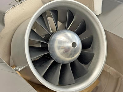
The Freewing Eurofighter Typhoon 8S High Performance 90mm EDF Jet V2 builds on the acclaimed 2023 Freewing Eurofighter platform with a focused set of V2 upgrades — and pairs them with the power of an 8S system designed to push the Typhoon to its performance ceiling. The 8S power system — built around a 4075-1350Kv brushless inrunner motor, 12-blade 90mm EDF, and 120A ESC with thrust reversing — delivers top-end EDF performance with the turbine-like sound and serious speed that define this version of the aircraft.

The V2 release introduces quick-disconnect wings for faster, tool-free assembly and breakdown at the field, along with formation lights integrated into the existing scale LED package for enhanced visual presence during flight. The center of gravity range has been extended to allow a more aft CG setting, with CG reference marks now located on the wing for faster, easier field setup. The V2 also debuts an all-new livery: the striking XI(F) Squadron RAF 100th Anniversary scheme of ZJ925, with a medium grey airframe, black spine and a dramatic black tail bearing the DXI eagle. A factory-installed EG01 gyro stabilization system rounds out the update, adding confidence on approach and during precision maneuvering without removing any of the aircraft's high-performance character.

All the hallmarks of the 2023 Freewing Eurofighter carry forward into the V2: scale CNC shock-absorbing landing gear with painted struts, sequenced gear doors, a functioning linear-actuated airbrake, spring-loaded auxiliary air inlets, and a scale weapon set with ten pylons. For pilots who want the fastest, most aggressive version of this iconic jet, the 8S High Performance V2 is the definitive choice.

A Livery That Steals The Show

The Eurofighter doesn't just get an upgrade — it gets a whole new look. The 100th Anniversary scheme of ZJ925 flown by XI(F) Squadron RAF is one of the most visually arresting liveries ever applied to this airframe: medium grey fuselage, black spine, and a bold black tail dominated by the DXI eagle. It looks incredible in the air and even better on the ground.

Quick-Disconnect Wings

Getting to the flight line just got faster. The V2 Eurofighter's quick-disconnect wings make assembly and breakdown easier than ever. Tool-free and straightforward — spend less time setting up and more time flying.

Factory EG01 Gyro — Right Out of the Box

The factory-installed EG01 6-axis gyro stabilizes the flight envelope and adds precision on approach — making the Eurofighter more locked in without dulling any of its high-performance character.

Scale Lighting Package

When the sun goes down, the Eurofighter lights up. Navigation, landing, and formation lights are integrated across the airframe — scale placement, serious visual impact, and the kind of presence on the flight line that makes every pass worth watching.

Scale Details That Deliver

CNC shock-absorbing struts, sequenced gear doors, a functioning linear-actuated airbrake, and a full ten-pylon ordnance load — the kind of details that make you stop and look twice before it even leaves the ground.

The Eurofighter Silhouette

Few combat aircraft have a more commanding presence in the sky. The canard-delta configuration, sculpted twin-engine fuselage, and aggressive stance of the Typhoon are captured faithfully in this model — a jet that turns heads from the moment it rolls onto the runway.


Features:

  • NEW V2! Quick-disconnect wings allow fast, tool-free assembly and disassembly for convenient transport and field setup,made in Freewing model
  • NEW V2! Formation lights integrated into the scale LED package for enhanced visual presence in flight
  • NEW V2! Factory-installed EG01 6-axis gyro for a more refined, confidence-inspiring flight experience
  • NEW V2! Wing-mounted CG reference marks and an extended aft CG range make dialing in the optimal CG faster and easier than ever
  • NEW V2! Updated XI(F) Squadron RAF 100th Anniversary livery — ZJ925 scheme with black spine and dramatic black tail with DXI eagle
  • 8S power system with 3668-1980Kv brushless inrunner motor and 12-blade 90mm EDF delivers strong performance and realistic turbine sound
  • 120A ESC with thrust reversing function for shorter landing rollouts
  • Functioning scale airbrake on linear electric actuator for high-alpha maneuvers and post-landing deceleration
  • Scale CNC shock-absorbing retractable landing gear with grey-painted struts and metal trunnions
  • Scale sequenced gear doors for added realism and improved aerodynamics
  • Spring-loaded auxiliary air inlets open and close automatically to feed the EDF based on air pressure differential
  • Scale LED landing and navigation lights for enhanced realism
  • Scale weapon set and pylons (10 total) included
  • 9g and 17g digital metal gear servos for precise, reliable control response
  • Nylon hinges on all control surfaces
  • Upgraded pushrod clevis and metal ball head connectors throughout

Package Includes:

  • Freewing Eurofighter Typhoon 8S High Performance 90mm EDF Jet V2 with Gyro — PNP
  • Factory-installed 4075-1350Kv brushless inrunner motor with 12-blade 90mm EDF unit
  • Factory-installed 120A ESC with 8A UBEC and thrust reversing
  • Factory-installed EG01 6-axis gyro
  • Scale electric retractable landing gear with CNC struts and sequenced gear doors (installed)
  • Factory-installed digital metal gear servos
  • Scale LED navigation, landing, and formation lighting system (installed)
  • Scale weapon set and pylons (10 total)
  • Instruction manual

Requires:

  • 7 Channel radio
  • 7 Channel receiver -
  • TWO 4 Cell 14.8V 5000 mAh LiPo batteries with EC5 connector
  • 6 Cell compatible battery charger

SPECIFICATIONS:

Model Scale

1/10.6

Wingspan

1030mm / 40.5in

Length

1450mm / 57in

Empty Weight

3230g (approx.)

CG (Center of Gravity)

215mm from the leading edge of the wing's root

Power System

4075-1350Kv Brushless Inrunner Motor (included)

Electronic Speed Control

120A with 8A UBEC and thrust reversing (included)

Propeller / EDF

12-Blade 90mm EDF (included)

Servos

  • 9g digital hybrid gear servo with 200mm lead : nose gear steering, landing gear door
  • 9g digital gear servo with 400mm lead : left canard, right canard -
  • 9g digital hybrid gear servo with 500mm lead : rear cabin door left
  • 9g digital hybrid reverse gear servo with 500mm lead : rear cabin door right
  • 17g digital metal gear servo with 100mm lead : rudder
  • 17g digital metal gear servo with 300mm lead : left aileron, right aileron

Landing Gear

CNC shock-absorbing retractable scale gear with metal trunnions (included)

Required Battery

6 Cell 22.2V 5000-6000mAh LiPo Battery with EC5 connector (required)

Required Radio

7+ Channel (required)

Ailerons

Elevons

Elevator

Elevons

Rudder

Yes

Flaps

No

Lights

Yes — Nav, Landing, Formation

Hinge Type

Nylon

Material

EPO Foam

Skill Level

Advanced/Expert

Build Time

3+ Hours

Recommended Environment

Outdoors

Recommended Runway Surface

Hard surfaces and short, well-manicured grass surfaces


Read more…

Freewing Avanti S 90mm Sport PNP Jet

Avanti S Green Ultra Performance 8S 90mm EDF Sport PNP Jet –SKU ID: FJ32512PG

The Avanti S 90mm EDF Jet is one of the most popular RC sport jets in the hobby, and now it’s bigger, faster and more capable than ever! The new Freewing Avanti S 90mm grows the popular Avanti S airframe to a 1380mm (54.3 in) wingspan and a 1460mm (57.5 in) length. That gives it more presence on the flight line and in the sky, plus the planted, locked-in feel that comes with a jet this size.

Track Flights

Power comes from a 12-blade 90mm EDF driven by a 4075-1350Kv brushless inrunner motor and an 8S LiPo setup. The system produces approximately 4700g (10.4 lb) of thrust, with the turbine-like sound 90mm EDF pilots love. Firewall the throttle and the Avanti S can be off the ground in as little as 15m (49 ft), with top speeds reaching 200 km/h (124 mph). Fast passes are crisp and precise, and the rolls are axial. When it’s time to slow down, the Avanti S has good stall manners and holds a smooth line on low, slow approaches. The 120A ESC with thrust reversing shortens landing rollouts, and the factory-installed EG01 6-axis gyro keeps the jet steady through gusty conditions and on final.

Under the foam, the Avanti S is engineered for strength and rigidity. The hollow main wing is built around a carbon fiber square tube and a wooden rib beam, and the horizontal stabilizers carry their own carbon reinforcement. Want to take it further? The bolt-on rear fuselage section accepts an optional thrust vectoring unit (FJ32511022), which turns the Avanti S into a 3D machine capable of flat spins, tight tumbles and pendulums.

Getting to the air is just as quick. The screw-less quick-release wing system slides each wing onto the carbon spar and locks it in place, and the wing’s electrical connections plug in automatically. The tail goes on with a few screws and a single wiring connection, so the jet goes from box to flight line in no time. Once it’s up, the fully painted green and white livery stands out in any sky, with LED lights at five positions and four sets of formation lights on the tail and fuselage sides. When it comes back down, the electric retracts ride on CNC aluminum shock-absorbing struts with sealed springs and damping grease that soak up firm landings.


The Best Got Bigger

The Best Got Bigger

The beloved Avanti S grows to a 1380mm / 54.3in wingspan and a 1460mm / 57.5in length. More size means more presence on the flight line, easier flying at a distance, and the planted, locked-in feel that only comes with a bigger jet.

Serious 90mm EDF Power

Serious 90mm EDF Power

A 12-blade 90mm EDF and a 4075-1350KV inrunner on 8S produce approximately 4700g / 10.4lb of thrust and top speeds of 200 km/h / 124 mph. You get the turbine-like sound 90mm pilots love, with plenty of vertical to go with it.

Factory EG01 Gyro

Factory EG01 Gyro

The factory-installed EG01 6-axis gyro smooths out gusty days and steadies the jet on final. Select modes from your transmitter and fly with more confidence from takeoff to touchdown.

Lit Up from Nose to Tail

Lit Up from Nose to Tail

LED lights at five positions and four sets of formation lights on the tail and fuselage sides keep the Avanti S visible against bright skies, overcast days and evening sessions.

Screw-Less Quick-Release Wings

Screw-Less Quick-Release Wings

Discover more
Track Defense News
Radio control
Remote Control Planes
 

Slide the wings onto the carbon spar, lock them in, and the electrical connections plug in automatically. No screws or loose wires to deal with, just less time on the bench and more time in the air.

Hardware That Holds Up

Hardware That Holds Up

A captured ball link sits centered between dual control horns, spreading the servo load evenly for sharp response and long-lasting durability. The horns are bonded and screwed into enlarged bases, and an L-bend pushrod with a keeper at the servo makes adjustments and maintenance quick and easy. Hidden hinges finish it off with clean, precise surfaces.

Landing Gear That Takes the Hit

Landing Gear That Takes the Hit

The electric retracts ride on CNC aluminum shock-absorbing struts with a fully enclosed design, so the springs and damping grease are sealed inside with nothing exposed. A built-in brace reinforces the nose strut, and full nose gear doors and main gear strut doors give the gear a clean, finished look.

A Livery That Pops

A Livery That Pops

The high-contrast green and white scheme is fully painted with no bare foam, so it looks sharp on the ground and makes orientation easy in the air. You always know which way the Avanti S is pointed. It’s also available in red and white.

Features:

  • Officially licensed by SebArt International, the original designer of the Avanti S
  • Larger 90mm platform with a 1380mm (54.3 in) wingspan and a 1460mm (57.5 in) length
  • 12-blade 90mm EDF driven by a 4075-1350Kv brushless inrunner motor and an 8S LiPo setup, producing approximately 4700g (10.4 lb) of thrust and top speeds of 200 km/h (124 mph)
  • 120A ESC with 8A UBEC and thrust reversing for shorter landing rollouts
  • Factory-installed EG01 6-axis gyro for that extra locked-in feel and added stability on approach and in gusty conditions
  • Screw-less quick-release wing system with plug-in wing connections for fast field assembly
  • Hollow main wing built around a carbon fiber square tube and wooden rib beam, plus carbon-reinforced horizontal stabilizers
  • Bolt-on rear fuselage section accepts the optional thrust vectoring unit (FJ32511022, sold separately) for 3D maneuvers
  • Electric retractable landing gear with fully enclosed CNC aluminum shock-absorbing struts (no exposed springs), damping grease and a built-in nose strut brace
  • Servo-driven nose gear doors and main gear strut doors
  • Flaps for slower, more controlled approaches
  • Striking high-contrast green and white livery for clear orientation in the air
  • Fully painted airframe with no exposed bare foam for a clean, finished look
  • LED lights at five positions, plus four sets of formation lights on the tail and fuselage sides
  • Cooling airways on both sides of the nose keep the battery and electronics cool in flight
  • 17g digital metal gear servos on all primary control surfaces and flaps
  • Hidden hinges and dual control horns with a centered captured ball link, mounted on enlarged, bonded-and-screwed bases for added strength
  • CG reference marks on the bottom of the wing for quick setup
  • Removable magnetic nose cone
  • Clear canopy with pilot figure
  • Large canopy hatch opens to a 280 x 83 x 70mm (11.0 x 3.3 x 2.8 in) battery bay for easy access to large packs

Includes:

  • Freewing Avanti S Green Ultra Performance 8S 90mm EDF Sport Jet with Gyro - PNP
  • Factory-installed 4075-1350KV brushless inrunner motor with 12-blade 90mm EDF
  • Factory-installed 120A ESC with 8A UBEC and thrust reversing
  • Factory-installed EG01 6-axis gyro
  • Electric retractable landing gear with CNC aluminum shock-absorbing struts (installed)
  • Nose gear doors and main gear strut doors (installed)
  • Digital servos (installed)
  • LED lights and formation lights (installed)
  • Removable magnetic nose cone
  • Instruction manual
  • Freewing 90mm Avanti S Red Green Jet manual(2026 new)

Requires:

  • 6-8 Channel radio (7 required for reverse thrust, 8 required for gyro mode selection) -
  • 6-8 Channel receiver (7 required for reverse thrust, 8 required for gyro mode selection) -
  • 8 Cell (8S) 29.6V 5000mAh LiPo setup with EC5 connectors
  • OR ONE 6 Cell 22.2V 5000mAh AND ONE 2 Cell 7.4V 5000mAh battery
  • 6 Cell compatible battery charger depending on battery selection


Specifications:

Build RC Models

Model Scale

N/A

Wingspan

1380mm / 54.3in

Length

1460mm / 57.5in

Weight

3125g / 110.2oz (without battery)

CG (Center of Gravity)

148–153mm / 5.8–6.0in measured from the leading edge of the wing at the fuselage (reference mark at 153mm / 6.0in on the bottom of the wing)

Power System

4075-1350KV inrunner motor (included)

Electronic Speed Control

120A with 8A UBEC and thrust reversing (included)

Propeller / EDF

90mm EDF, 12-blade (included)

Servos

  • 9x digital servos (included)
  • Aileron (2) - FSS31172-100
  • Left Elevator - FSS31172-300
  • Right Elevator - FSS31172R-300
  • Left Flap - FSS31172-300
  • Right Flap - FSS31172R-300
  • Rudder - FSS31172-200
  • Nose Wheel Steering - FSS31093-700
  • Nose Gear Door - FSS31091-800

Landing Gear

CNC-machined aluminum, shock absorbing, retractable landing gear (included)

Required Battery

2x 4 Cell 14.8V 5000mAh LiPo, OR 1x 6 Cell 22.2V 5000mAh + 1x 2 Cell 7.4V 5000mAh LiPo, for 8S operation (required)

Required Radio

6-8 Channel minimum (7 required for reverse thrust, 8 required for gyro mode selection)

Ailerons

Yes

Elevator

Yes

Rudder

Yes

Flaps

Yes

Lights

Yes (LED/Formation)

Brakes

Thrust Reversing

Gyro

Yes (Freewing EG01)

Hinge Type

Nylon

Material

EPO Foam with carbon fiber reinforcement

Skill Level

Intermediate to Advanced

Build Time

1+ Hours

Recommended Environment

Outdoors

Recommended Runway Surface

Hard surfaces and short, well-manicured grass surfaces


Freewing Avanti S Green Ultra Performance 8S 90mm Sport PNP Jet
  • Freewing Avanti S Green Ultra Performance 8S 90mm Sport PNP Jet
  • Freewing Avanti S Green Ultra Performance 8S 90mm Sport PNP Jet
  • Freewing Avanti S Green Ultra Performance 8S 90mm Sport PNP Jet
  • Freewing Avanti S Green Ultra Performance 8S 90mm Sport PNP Jet
  • Freewing Avanti S Green Ultra Performance 8S 90mm Sport PNP Jet
 

Freewing Avanti S Green Ultra Performance 8S 90mm Sport PNP Je


Read more…

For UAV developers, adding a distance sensor is not just about measuring how far away an object is. The sensor also needs to deliver usable data at the right rate, communicate reliably with the onboard electronics, and perform consistently under real operating conditions.

One option worth exploring for custom measurement payloads is a phase-based laser distance sensor such as the LDJU, which uses indirect Time-of-Flight (iToF) technology.

Why Does Measurement Frequency Matter?

When a UAV is moving, the distance to a target can change continuously. Depending on the application, a low measurement rate may provide enough information for occasional inspection, while a higher rate can offer more frequent updates for dynamic measurement experiments.

The LDJU version discussed here supports continuous measurement frequencies of up to 10 kHz under specified operating conditions. Its stated measurement range is 0.2–30 m, with a measurement resolution of 1 mm.

These specifications may make it worth evaluating for custom UAV payload prototypes that require frequent distance readings over short to medium distances.

However, a high measurement frequency does not automatically guarantee better results in flight. Target reflectivity, ambient light, vibration, sensor alignment, data processing, and timestamp synchronization can all affect the usefulness of the measurements.

Potential UAV Development Applications

Depending on the payload design and field-test results, a high-rate distance sensor could be explored for applications such as:

  • Inspection payloads: collecting distance readings while a camera observes structures or equipment.

  • Proximity measurement experiments: evaluating how distance data behaves as a UAV approaches a target.

  • Motion and measurement research: comparing sensor readings with UAV position and payload orientation.

  • Custom robotic systems: integrating laser distance data into an onboard controller or companion computer.

These are potential development applications, not pre-validated LDJU integrations. The appropriate configuration depends on the required range, target surface, environmental conditions, and system-level testing.

Interface and Integration Considerations

The LDJU interface depends on the specific version. Available options include USB 2.0 or USART, while RS232 and RS485 communication may be supported through an external level-conversion module.

Before integrating the sensor into a UAV, developers should verify the exact interface and electrical requirements of their unit. They should also confirm that the onboard controller can receive and process data at the intended measurement rate.

A practical evaluation could begin with a bench test:

  1. Connect the sensor to a suitable power supply and host controller.

  2. Record continuous distance readings at several known target distances.

  3. Check data continuity and measurement stability at the intended update rate.

  4. Repeat the test with different target surfaces and lighting conditions.

  5. If the sensor is mounted on a moving payload, test the effects of vibration and orientation changes.

For applications requiring synchronized measurements, recording timestamps alongside distance data is also important.

Resolution Is Not the Same as Accuracy

The LDJU specification lists a measurement resolution of 1 mm. Resolution describes the size of the measurement increments; it should not be interpreted as a guarantee that every reading is accurate to within 1 mm.

The manual specifies accuracy separately as ±(3 mm + D × 1/10000), where D is the measured distance. Actual performance can also depend on the operating environment and target characteristics.

For UAV applications, it is therefore important to evaluate both the specified accuracy and the repeatability of readings under representative test conditions.

A Starting Point for Custom Payload Development

The LDJU provides a measurement range of 0.2–30 m and continuous measurement frequencies of up to 10 kHz for the version discussed here. These characteristics offer a starting point for developers investigating high-rate distance measurement in custom embedded systems.

As with any sensor intended for use on a moving platform, suitability should be confirmed through mechanical, electrical, and field testing rather than inferred from the datasheet alone.

For more information about Meskernel's laser distance measurement solutions, visit Meskernel or contact us.

When evaluating a high-rate distance sensor for a moving UAV payload, which factor has the greatest impact on your design: measurement frequency, accuracy, interface bandwidth, or stability under vibration?

Read more…

Benewake Unveils the NOVA20 Solid-State Near-Field Linear LiDAR: Eliminating Robotic Close-Proximity Perception Blind Spots with a 20-Point Array

Recently, Benewake officially launched the NOVA20, a solid-state near-field linear LiDAR designed specifically for embodied AI and mobile robots. Featuring 20 detection channels that form a 40° fan-shaped field of view, the NOVA20 covers the close-proximity zone from 5 centimeters to 1 meter in front of the robot. Working in tandem with 360° rotating LiDARs responsible for long-range scanning, it provides robots with a low-power, glare-resistant, and flexible near-field safety perception solution that can be distributed along the robot's body.

文章内容

▲ Benewake NOVA20 solid-state near-field linear LiDAR (right), comparable in size to a beer bottle cap

Adopting a pure solid-state design with no moving parts, the NOVA20 is roughly the size of a beer bottle cap (25 × 22 × 13 mm typical), weighs less than 5 grams, consumes an average power of under 1 watt, and operates reliably under 100 Klux of intense ambient light.

The Dilemma of Embodied Robots: "Seeing the Distance, Missing the Meter"

As embodied AI accelerates toward commercial deployment, a fundamental issue has become increasingly prominent: the "close-range safety zone" within 1 meter in front of the robot remains a blind spot in existing sensing setups. While 360° rotating LiDARs handle long-range scanning, they leave a blind zone right next to the robot. Meanwhile, head-mounted cameras suffer from a short-range blind lower limit and are easily occluded by the robot's own limbs. Traditional solutions also fall short: ultrasonic and infrared proximity switches offer too few measurement points with large blind spots; triangulation-based linear lasers fail completely under outdoor bright light; and common 3D array solutions struggle with high-reflectivity crosstalk, bulkiness, and high costs.

文章内容

▲ Stair edges, side obstacles, and other close-range hazards often fall outside the field of view of primary head-mounted cameras

This is not a niche problem. According to IDC data, global shipments of humanoid robots reached 18,000 units in 2025, and TrendForce projects global shipments to exceed 50,000 units in 2026. As robots enter real-world environments such as factories and commercial facilities at scale, physical guardrails and safety supervisors cannot always be present. Promptly detecting people and obstacles and slowing down or stopping before physical contact becomes an essential capability.

Furthermore, safety should not rely solely on high-level models prone to misinterpretation. Even the most advanced end-to-end models cannot deduce spaces occluded by the robot's own body. Continuously offloading high-frequency judgments—such as whether there is an object nearby and how far it is—to models drains the robot's limited computing power, battery, and thermal space. The industry urgently needs a deterministic ranging bypass independent of high-level models that can be independently verified: models handle understanding and planning, while underlying control systems rely on this data to slow down, detour, or stop. The updated ISO 10218 series of industrial robot safety standards (2025 edition) has incorporated collaborative safety capabilities such as "Speed and Separation Monitoring (SSM)", and the upcoming ISO 25785-1 standard for dynamically stable mobile robots is also under development—using deterministic ranging to guard human-robot separation is becoming a clear industry direction.

Designed precisely to bridge this gap, the NOVA20 integrates solid-state device architecture and array design into a systematic near-field safety solution, combining five major characteristics into a single LiDAR: pure solid-state architecture, linear array detection, compact size, high cost-effectiveness, and outdoor usability.

文章内容

▲ 360° rotating LiDAR looks far, while the NOVA20 clears the blind spots right ahead: long-range and near-field sensors perform their respective duties

Highlight 1: A 20-Point Array Opening a 40° Fan-Shaped Sector, Clearing the Near-Field with a Single Module

The NOVA20 deploys 20 detection channels within a 40° field of view (evenly distributed across ±20°), measuring distances collaboratively at a 10 Hz frame rate with centimeter-level precision. Unlike single-point solutions that only register a sudden change, 20 channels can simultaneously observe distance variations across different directions within a fan-shaped zone. For instance, when a robot approaches the edge of a step, readings in a specific direction suddenly increase, enabling the system to react rapidly and providing more comprehensive near-field data for fall prevention and lateral collision avoidance.

Near-field detection requires not just visibility, but complete visibility. With a 10% target reflectivity and 100 Klux ambient light, the NOVA20 achieves a range of up to 1 meter with a blind zone of less than 5 centimeters. From the far end of its range down to the 5-centimeter close-proximity end, distance data remains continuous—ensuring that as obstacles get closer, readings stay online, allowing robots to "get close while seeing clearly".

Highlight 2: 100 Klux Glare Resistance and Zero Crosstalk, Reliable Under Intense Outdoor Sunlight

While triangulation linear lasers go blind outdoors, the NOVA20 resists up to 100 Klux of ambient light—equivalent to direct midday sunlight. This means the exact same near-field safety solution can scale seamlessly from indoor environments to inspection, logistics, and outdoor operations. When a robot transitions from a warehouse to an open-air loading dock where lighting changes drastically within seconds, the NOVA20 continues outputting reliable data without data confusion caused by lighting shifts.

To solve "crosstalk"—a long-standing industry headache in array LiDARs where a high-intensity echo "bleeds" into adjacent channels and mixes with real scenarios—the NOVA20 adopts a time-division multiplexing, sequential readout design. This ensures that each echo falls exclusively into its designated channel, translating real environments into clear, distinct points. By eliminating false signals, robots avoid emergency stops or detours caused by non-existent obstacles, making zero-margin edge-following operations far more reliable.

Highlight 3: Beer Bottle Cap Size, Under 5 Grams, Under 1 Watt—Distributed Along the Body and Deployed On Demand

Adopting a pure solid-state architecture with no moving parts, the NOVA20 measures only 25 × 22 × 13 mm (typical), comparable in size to a beer bottle cap. Weighing less than 5 grams (lighter than a standard one-yuan coin) and consuming an average power of less than 1 watt, it is small enough to mount directly onto robot bodies, robotic arms, and limbs for close-range anti-collision protection. Low power consumption also means multi-point deployment adds no extra thermal or stability burden to the system, ensuring long life and outdoor durability.

The NOVA20 does not output images; instead, it provides direct distance data to the underlying control system. This shortens the data pipeline, lowers latency, and preserves precious computing power for semantic understanding, task planning, and fine manipulation—much like how a human doesn't need to recognize a table's category and shape every time they check how far their hand is from a table corner. It acts like a circle of non-contact neural endings outside the robot's "skin," detecting distance changes before physical impact occurs rather than sensing force after a collision.

This design clearly defines product boundaries: the NOVA20 does not replace vision and models, nor does it handle fine force control post-contact; instead, it provides a low-burden, task-specific distance input stream. Paired with a UART interface and ROS/Linux/Windows support, original equipment manufacturers (OEMs) can flexibly deploy sensors based on risk points—covering critical locations first and expanding points according to robot morphology and application scenarios. With its compact size, low power, zero compute overhead, and controllable cost, the NOVA20 integrates directly into mass-production robot BOMs to support large-scale batch deployment.

A Single LiDAR Resolving Three Major Near-Field Challenges for Robots

Focusing on the most typical near-field risks for robots, the NOVA20 underpins three core capabilities: edge-following, fall prevention, and collision avoidance.

Edge-Following: When maintaining a centimeter-level distance from a wall, the robot stays close, moves straight, and avoids scraping.

Fall Prevention: Beams constantly scan the ground ahead, combining 20 points into an area scan to detect slopes and drop-offs in advance rather than waiting for single-point ranging to catch a sudden change.

Collision Avoidance: Beams target obstacles ahead, triggering alerts and stops upon approach to protect the system before physical contact occurs.

文章内容

▲ Edge-following, fall prevention, and collision avoidance: Three core near-field safety capabilities supported by the NOVA20

Regarding installation, the NOVA20 follows an "on-demand deployment" design: humanoids on the chest, wrists, and ankles; quadrupeds on the jaw and feet; mobile chassis at the four corners—mounted wherever blind spots exist to piece together a localized safety perimeter without stacking bulky, expensive sensors all over the body. The blind spots of embodied AI are precisely where the NOVA20 was born to serve.

文章内容

▲ Chest, wrists, ankles, and chassis corners—mount wherever blind spots exist

(Specific mounting locations, detection performance, and control strategies should be verified against specific robot structures and actual environments)

Key Parameters

文章内容


About Benewake

Founded in 2015, Benewake is a LiDAR enterprise dedicated to AI perception for robots and the physical world. Grounded in full-stack technical capabilities spanning "optics, mechanics, electronics, software, algorithms, and chips," the company builds a full-scenario "Eyes of the Robot" product matrix, striving to create perception infrastructure for the physical intelligence era.

Solid-state LiDAR represents Benewake's core technical accumulation: from the first-generation solid-state flash LiDAR CE30 in 2017, to the solid-state small-angle linear LiDAR NOVA in 2024, and now the newly released pure solid-state near-field linear LiDAR NOVA20, nine years of continuous evolution across three generations have established a secure and reliable perception foundation for physical intelligence.

Read more…

SHANGHAI — At the 2026 World Artificial Intelligence Conference (WAIC), almost every embodied AI robot showcasing its operational capabilities performed inside a guarded enclosure. Nearby safety personnel kept their eyes fixated on three specific areas: near the feet, around the hips, and along the arm movement trajectories.

These spots share a common physical blind spot: they all fall outside the field of view (FOV) of the head-mounted primary cameras, obscured by the robot's own body.

This blind spot is not a flaw in artificial intelligence models. Even the most advanced end-to-end vision-language-action (VLA) models cannot infer unobservable, occluded spaces—it is a matter of fundamental geometry. Yet, for robots to safely navigate human-centric environments, they must first master this critical distance of 5 centimeters to 1 meter—detecting floor drops before stepping forward or sensing nearby people when turning around.

The Divergence in Safety Architecture

Industry leaders like Tesla and Figure rely heavily on vision, multimodal models, and end-to-end learning at the core of their control systems, attempting to connect all sensors and actuators via a unified neural network. While this approach excels at high-level scene understanding and generalization, it struggles with two fundamental issues: physical body occlusions and the heavy compute overhead required for high-frequency, low-semantics proximity checks.

This challenge has shifted the industry toward a functional division of labor. While AI models handle perception and task planning, a dedicated ranging channel guards the safety baseline at close quarters, enabling lower-level control systems to slow down, detour, or stop instantly. This independent pipeline delivers shorter response latency and predictable failure modes—vital requirements for commercial mass production and customer acceptance testing.

Transitioning from AI Models to System Engineering

Robot safety is transitioning from a model capability issue into a full-scale system engineering challenge. According to market research firm IDC, global shipments of humanoid robots surpassed 18,000 units in 2025, with TrendForce projecting that figure to top 50,000 units in 2026. As robots enter factories and commercial facilities, external physical barriers and safety supervisors will no longer be practical.

Updated international standards, such as ISO 10218 (2025) for industrial robots and the developing ISO/CD 25785-1 for dynamic mobile robots, explicitly require strict risk assessment, safety integration, and speed and separation monitoring.

However, onboard computing power, battery capacity, and thermal space remain strictly limited. Offloading basic proximity detection entirely to heavy vision models drains power, increases latency, and inflates hardware costs.

To address this gap, LiDAR developer Benewake has launched the NOVA 20, a solid-state near-field LiDAR module designed specifically for the 5 cm to 1 m range. As Dr. Yuan Li, Founder and CEO of Benewake, highlighted in a public interview:

"As the first unit among perception, prediction, and planning-and-control, LiDAR allows us to see the bigger picture from smaller details during the perception phase."

 
文章内容

Consuming under 1 watt, weighing less than 5 grams, and measuring just 25 mm × 22 mm × 13 mm, the NOVA 20 acts as a non-contact tactile layer distributed across wrists, torsos, knees, or ankles.

 
文章内容

Solving the Five Proximity Challenges

The NOVA 20 addresses five primary engineering pain points in mass-production robotics:

 
文章内容
  1. Complete Coverage: Featuring a 40° FOV across 20 channel detectors, it monitors a fan-shaped zone with centimeter-level precision to prevent falls and lateral collisions.
  2. Deterministic Control: By outputting raw distance data directly rather than heavy image streams, it reduces latency and mitigates multi-device cross-talk.
  3. Compute Offloading: Low power consumption and minimal payload requirements free up primary computing resources for semantic reasoning and manipulation.
  4. All-Weather Adaptability: Capable of operating under 100 Klux ambient light (equivalent to direct sunlight) with a blind zone under 5 cm, it enables seamless indoor-to-outdoor transitions.
  5. Bill of Materials (BOM) Integration: Utilizing a standard UART interface, it allows manufacturers to cost-effectively deploy sensors across critical risk points during mass production.
 
文章内容

Redundancy Over Singular Perception

The debate between pure-vision setups and multi-sensor fusion is reaching a consensus. Future robotic safety architectures will rely on hardware redundancy across multiple sensor types and control tiers. Large models will govern high-level understanding and task execution, while dedicated physical sensors defend safety baselines at the lowest level.

文章内容

Reflecting on the relationship between intelligence and perception, Dr. Li noted:

"The emergence and growth of strong intelligence will inevitably require strong perception, but 'strong' never means farther, larger, or more complex. For the robotics industry, true strong perception means reliably getting safety right at the exact distance where it is needed most—using hardware that is small, energy-efficient, and affordable enough."

文章内容


Read more…

BEIJING, China — Benewake has officially launched the NOVA20, a next-generation solid-state multi-point LiDAR designed for robotic platforms. As robots move from controlled environments into increasingly complex real-world applications, reliable close-range perception, obstacle avoidance, and human-robot safety have become critical requirements. NOVA20 focuses on the one-meter space around robots, providing direct physical distance sensing to address near-field perception challenges in existing robotic sensor architectures.

The Challenges of Near-Field Robot Perception

Current robotic perception systems face limitations in close -range scenarios:

  • Blind Zones of 360° Spinning LiDAR:While conventional 360° spinning LiDARs excel at long-range mapping and global localization, their sensing coverage can be limited within tens of centimeters around the robot, leaving a gap in near-field safety perception.
  • Occlusion and Lighting Limits in Vision:Cameras mounted on the head or torso can be occluded by the robot’s own chassis or articulating limbs. Furthermore, vision-based perception can be affected by challenging lighting conditions and requires compute-intensive processing.
  • Coarse Resolution of Legacy Sensors:Ultrasonic and single-point infrared sensors offer limited measurement points, making it difficult to reliably resolve low-profile obstacles or sharp drop-offs.


How NOVA20 Addresses These Limitations

NOVA20 is designed to overcome these challenges through a compact solid-state sensing architecture.

  1. The sensor features a 20-point detection array with a 40° field of view, enabling multi-point distance sensing across a detection range of 0.05-1m (1m @ 10% reflectivity under 100 klux ambient light).
  2. Weighing less than 5g and consuming less than 1W of power, NOVA20 adopts a compact design with no mechanical moving components, enabling flexible deployment across different parts of robotic platforms, including the chassis, body, wrist, waist, knee, and ankle areas.
  3. NOVA20 supports operation under strong ambient light conditions up to 100 Klux and directly outputs physical distance information without generating 2D images, reducing unnecessary image data collection and host-level vision processing requirements.

By providing an independent near-field sensing layer, NOVA20 complements existing LiDAR and vision systems to improve robotic safety perception.


Primary Applications of NOVA20

  • Lateral Edge-Following and Narrow Passages:Provides multi-point lateral distance measurements for AMRs, commercial cleaning robots, and robotic mowers, supporting more precise wall-following and reducing the risk of side collisions in narrow environments.
  • Ground Edge Recognition and Anti-Drop:Detects negative obstacles, staircase edges, and sudden elevation drops for bipedal humanoids, quadrupeds, and wheeled platforms, helping reduce the risk of step-off accidents.
  • Human-Robot Proximity and Pre-Contact Deceleration:Provides near-field distance measurements for delivery robots, patrol robots, and collaborative robotic platforms, supporting deterministic speed reduction before physical contact.


About Benewake

Founded in 2015, Benewake specializes in LiDAR technology and physical-world AI perception. The company has delivered more than 3 million units across over 90 countries, supporting developers and manufacturers in building safer robotic systems.

Organizations interested in technical integration, evaluation opportunities, or robotic platform collaboration can visit Benewake’s official website for more information.


Media Contact

Benewake (Beijing) Co., Ltd.

Email: bw@benewake.com

Website: https://en.benewake.com/

Read more…

Step by Step Assembly Guide: Freewing F 35C 110 mm EDF Jet (PNP Gyro Version, Item FJ50111PG)

Freewing F-35C 110mm EDF jet manual(2026 new)

Freewing F-22 Raptor v2 90mm edf jet manual(2026 new)

This build follows the official factory workflow, optimized for the 1/9.6 scale 110 mm F 35C with QUICK II tool free quick release wings, pre installed servos, 6 axis EG01 gyro, sequenced electric retract landing gear, LED navigation/afterburner lights, and a factory mounted 110 mm in runner EDF + 130 A HV ESC (12S power).
Air Force
Pre note: Most electronics (EDF, ESC, gyro, landing gear servos, LED wiring, fuselage servos) are pre installed in factory. Only airframe assembly, wiring plug ins, radio binding, battery fitting, control linkage tuning and CG setup are required.

Freewing F-35C Lightning II Super Scale 110mm EDF Jet


Freewing F-35C Lightning II Super Scale 110mm EDF Jet

Discover more
Drones & RC Aircraft
RC Electronics
Shipping Services


Freewing K-8 Karakorum 80mm EDF PNP Jet


Freewing K-8 Karakorum 80mm EDF PNP Jet


Tools you need

Phillips head screwdriver (1.5 mm 3 mm)
 
Tape (to protect EPO foam from scratches)
 
Zip ties (for cable management)
 
Double sided hook and loop tape (battery mounting)
 
Digital scale + balancing stand (for CG check)
 
12S Li Po battery (6 000�C8 000 mAh, 60C�C100C discharge rating)
Electricity

Freewing F-35C Lightning II 110mm EDF Jet Spare parts

Freewing F-35C Lightning II 110mm EDF Jet Spare parts


All Spare Parts are available in stock.

1. Send email to us,our e-mail is sales@freewing-model.com

we will reply message within 24 hours.

2.Live Chat Online in the following,


Discover more
Physics
Defense Industry
Boats & Watercraft


This Product is available in stock,we will ship the package box within 48 hours after the buyers pay money via paypal.


Spare parts For Freewing F-35C Lightning II 110mm EDF Jet Spare parts

Parts NumberDescriptionImage
FJ5011101Freewing F-35C Lightning II 110mm EDF Jet FuselageFreewing F-35C Lightning II 110mm EDF Jet Fuselage
FJ5011102Freewing F-35C Lightning II 110mm EDF Jet Main wingFreewing F-35C Lightning II 110mm EDF Jet Main wing
FJ5011103Freewing F-35C Lightning II 110mm EDF Jet Vertical StabilizerFreewing F-35C Lightning II 110mm EDF Jet Vertical Stabilizer
FJ5011104Freewing F-35C Lightning II 110mm EDF Jet Horizontal Stabilizer SetFreewing F-35C Lightning II 110mm EDF Jet Horizontal Stabilizer Set
FJ5011105Freewing F-35C Lightning II 110mm EDF Jet Nose ConeFreewing F-35C Lightning II 110mm EDF Jet  Nose Cone
110mm EDFFreewing 4678-680KV Inrunner Motor 110mm 12-blade EDF 6S Power SystemFreewing F-35C Lightning II 110mm EDF Engine Power system
FJ50111061Freewing F-35C Lightning II 110mm EDF Jet CockpitFreewing F-35C Lightning II 110mm EDF Jet Cockpit
FJ50111071Freewing F-35C Lightning II 110mm EDF Jet Decal AFreewing F-35C Lightning II 110mm EDF Jet Decal A
FJ50111072Freewing F-35C Lightning II 110mm EDF Jet Decal BFreewing F-35C Lightning II 110mm EDF Jet Decal B
FJ50111073Freewing F-35C Lightning II 110mm EDF Jet Decal CFreewing F-35C Lightning II 110mm EDF Jet Decal C
FJ50111081Freewing F-35C Lightning II 110mm EDF Jet front Landing set Strut and Wheel with RetractFreewing F-35C Lightning II 110mm EDF Jet front Landing set Strut and Wheel
FJ50111087Freewing F-35C Lightning II 110mm EDF Jet Left Landing set Strut and Wheel with RetractFreewing F-35C Lightning II 110mm EDF Jet Left Landing set Strut and Wheel with Retract
FJ501110812Freewing F-35C Lightning II 110mm EDF Jet Right Landing set Strut and Wheel with RetractFreewing F-35C Lightning II 110mm EDF Jet Right Landing set Strut and Wheel with Retract

All Spare Parts are available in stock.

Radio Control & Modeling
Discover more
Model Rockets
Radio Control Drones
Propeller Airplanes
 

1. Send email to us,our e-mail is sales@freewing-model.com

we will reply message within 24 hours.

2.Live Chat Online in the following,

Stage 1: Horizontal stabilizer (Elevator) installation (tail first)

  1. Align the plastic adapter lugs on each left/right horizontal stabilizer into the pivot slots on the rear fuselage tail boom.
  2. Plug the elevator servo extension wire from each horizontal tail into the matching fuselage servo plug.
  3. Center the elevator surface perfectly, then secure the two side horizontal tail mounts with FA3��8 mm machine screws (4 total). Do not over tighten; over torque will strip EPO foam threads.
  4. Check free elevator travel: full up/down motion without binding or cable snagging. Secure loose wiring with zip ties inside the fuselage tail cavity.

Stage 2: Twin canted vertical stabilizers (Rudders) assembly

  1. Route vertical tail servo wires through the fuselage vertical fin mounting holes. Connect each rudder servo plug to the fuselage extension harness one by one.
  2. Seat each canted vertical fin fully down onto the fuselage rear mounting bosses.
  3. Fasten using 4�� FA3��8 mm screws to lock the vertical stabilizers in position.
  4. Manually test rudder left right movement; confirm wiring is not pinched between stabilizer and fuselage frame.

Stage 3: Main wing installation (QUICK II tool free plug and lock system, signature for this 110 mm F 35C)

This model uses a carbon fiber main spar plus push button quick lock latches (no wing mount screws required for field assembly):
Aviation Industry
  1. Slide the thick main carbon fiber spar fully through the fuselage wing root tunnel, spanning left to right wing sockets.
  2. Unlock the wing latch buttons on both fuselage sides (press the button down to release the lock mechanism).
  3. Plug the aileron flap servo plugs from each main wing into the corresponding fuselage harness connectors. Double check polarity (pin alignment) to avoid reversed servo operation.
  4. Slide left right main wing wing root lugs onto the carbon spar, push the wings flush against the fuselage shoulder.
  5. Release the latch buttons. The spring loaded latches will pop up and mechanically lock the wings firmly onto the airframe. Gently tug each wing to confirm zero play.
For long term static display: Optional set screws can be tightened for extra wing rigidity; leave loose for easy transport disassembly.

Stage 4: Nose section, cockpit canopy and intake duct fit up

  1. Fit the plastic cockpit tub/pilot detail piece into the forward fuselage cockpit cavity.
  2. Clip the clear canopy hatch onto the fuselage nose cockpit hinge points; confirm the canopy latches shut securely.
  3. Install the nose cone; ensure the intake air duct channel inside the nose perfectly aligns with the front inlet leading to the 110 mm EDF unit. Any gaps will reduce EDF thrust performance. Seal minor intake gaps with thin foam tape if there is air leakage.

Stage 5: Landing gear & sequenced gear door pre check (factory pre mounted electric retracts)

All landing gear servos, shock absorber struts, gear door servos and sequencing wiring are pre installed:
  1. Connect the landing gear harness plug to the main gyro/central electronics board inside the fuselage.
  2. Power the system on (via temporary battery) and cycle landing gear up/down on your radio transmitter.
  3. Verify the gear doors open first, struts extend, then doors close (scale sequenced operation). Adjust servo linkage set screws if doors bind, stay ajar or jam.
  4. Check nose gear steering movement matches your transmitter rudder input.

Stage 6: LED & afterburner light wiring connection

  1. Locate the navigation light plug (wing/fuselage formation lights) and afterburner LED plug (exhaust nozzle) inside the rear fuselage.
  2. Plug both into the dedicated LED port on the Freewing EG01 6 axis gyro unit.
  3. Test: Navigation lights turn on when the radio system powers up; the afterburner LED illuminates under high throttle input (factory pre programmed).

Stage 7: Radio system wiring, gyro setup and transmitter binding

  1. Plug these components into the EG01 gyro input ports:
    • ESC signal wire
    • Aileron, elevator, rudder servo main harness lead
    • Landing gear servo harness
    • LED lighting harness
  2. Bind your 2.4 GHz receiver to your radio transmitter, then plug the receiver into the gyro��s receiver input port.
  3. Gyro baseline setup (critical for this large jet):
    1. Place the jet on a perfectly flat, level surface, keep the aircraft stationary.
    2. Power on the radio first, then plug in the 12S flight battery to power the jet.
    3. Hold the trim sliders neutral while the gyro auto calibrates (LED flashes solid once calibration finishes).
    4. Set gyro gain on your transmitter (start at 50 60% for maiden flight; increase for smoother high speed flight, reduce if the jet oscillates/wobbles).

Freewing F-35C Lightning II Super Scale 110mm EDF Jet


Freewing F-35C Lightning II Super Scale 110mm EDF PNP Jet


Freewing F-35C Lightning II 12S 110mm ARF Plus jet


Freewing F-35C Lightning II 12S 110mm ARF Plus jet


Stage 8: Battery installation & Center of Gravity (CG) tuning (most critical flight step)

  1. Open the top fuselage battery hatch behind the cockpit. Secure the 12S Li Po battery using hook and loop tape on the battery tray.
  2. Official CG datum for the Freewing 110 mm F 35C: 110�C115 mm back from the leading edge of the main wing root (fuselage wing shoulder).
    • Move the battery forward if the nose pitches up (tail heavy, unstable).
    • Shift the battery rearward if the nose dives sharply (nose heavy, sluggish turns).
  3. Once CG is correct, secure excess battery power wiring with zip ties to prevent loose wires from hitting the 110 mm EDF fan.

Stage 9: Final pre flight control surface check

  1. Double check all control surface directions:
    • Aileron: Right stick right next right aileron dips down
    • Elevator: Right stick back next elevator deflects upward
    • Rudder: Left stick left next vertical tail rudder moves left
  2. Reverse servo direction in your radio menu if any surface moves backwards.
  3. Cycle landing gear, test flaps, check all wiring is clear of moving parts and the EDF inlet/exhaust.
  4. Inspect the 110 mm EDF fan; ensure zero debris inside the fan shroud before the maiden flight.

Quick assembly order recap (field setup version for flying field fast build up)

  1. Attach horizontal tails . 2. Attach vertical stabilizers . 3. Install carbon spar + lock on main wings next 4. Plug in all servo/LED plugs next 5. Mount battery next 6. CG balance next 7. Gyro recalibrate next 8. Pre flight check next Fly

Freewing K-8 Karakorum 80mm EDF PNP Jet

Freewing K-8 Karakorum 80mm EDF PNP Jet


Freewing K-8 Karakorum 70mm EDF PNP Jet

Freewing K-8 Karakorum 70mm EDF PNP Jet


3.Freewing F-35 110mm EDF jet

Air Force

Freewing F-35C Lightning II Super Scale 110mm EDF Jet with Gyro RC Airplane

Read more…

EFT N680: Entry Level DIY Drone Platform

Published: 9, 24, 2026 , | Written by Louis, Technical Department Manager

Programmable drones on the market generally fall into two categories. The first includes block based programming toys that are affordable and well suited for short term, hands on experiences. However, these systems are essentially closed “black boxes.” Once students want to explore the underlying logic behind flight control decisions, they offer limited opportunities for deeper technical learning. 


The second category consists of high performance, open source research platforms. While these platforms provide extensive development capabilities, they are often expensive, delivered as bare bone kits, and require a relatively high level of technical knowledge. This creates a steep learning curve for students who are just beginning to explore drone development. coding drone

The EFT N680 is designed to bridge this gap.

As an entry level open source drone development platform, the N680 enables new students to progress from basic hands on training to real flight testing, while giving graduate students and advanced learners a practical platform for algorithm research and academic projects. Its flight control architecture is open at the core, while its modular design allows students to inspect, maintain, and replace individual components themselves.

With comprehensive technical documentation and supporting software, instructors can integrate the N680 into existing courses without having to redesign the entire curriculum.

 31268874897?profile=RESIZE_710x

What Is the EFT N680?

The EFT N680 is a 680 mm wheelbase quadcopter open source drone development platform. Unlike closed educational drones that rely primarily on simplified demonstration applications, the N680 is a professional experimental platform designed to combine stable flight performance with hands on, in depth learning.

Its unified airframe and open source flight control system make it particularly suitable for universities, vocational schools, STEM program leaders, and drone developers. education drone The platform is open and easy to maintain, allowing for repeated use in teaching across academic years. 


Design and Configuration

The N680 adopts a fully modular architecture. Its main frame uses a high strength, one piece injection molded nylon structure, combined with carbon fiber arms and landing gear. The fuselage provides ample internal space and reserved mounting points for payloads and peripherals, allowing students to integrate cameras and other equipment for experiments such as aerial imaging and visual navigation.

Featuring a modular design, components such as the arms, motors, ESC/PDB, propellers, snap-fit sealed battery compartment, and flight controller can be replaced independently, facilitating assembly, setup, and maintenance. entry level drone

This modular approach is particularly valuable in classroom environments. If a component is damaged during a test flight, students can replace the affected module instead of replacing the entire aircraft. This helps minimize downtime and keeps practical training on schedule. 

A single N680 can support multiple educational experiments covering flight principles, propulsion systems, embedded control, and complete aircraft assembly.

Open Source Flight Control and Development

The aircraft is equipped with the N1 mini open source flight controller, built around a high performance STM32H7 processor.

It features a built in high precision magnetic compass and can be paired with an external GPS compass to provide redundant heading sensing and improve positioning stability.

The flight controller provides a broad range of peripheral interfaces, including 8 motor output channels and 4 servo channels, with reserved expansion buses for CAN, serial, and I2C devices.

The N680 natively supports ArduPilot open source firmware and the MAVLink communication protocol, allowing students and developers to work within a mature open source ecosystem supported by extensive documentation and community resources.

A Progressive Learning Path

The N680 is designed around a progressive learning path.

At the beginner level, students can use ArduPilot to configure and test flight modes, parameters, and waypoint missions. This allows them to understand fundamental drone control concepts through direct interaction with a real aircraft rather than relying solely on simulation or block based programming.

At the advanced level, users can connect an onboard computer and deploy ROS nodes, with access to attitude, position, and velocity control commands. This creates opportunities for projects involving machine vision, autonomous navigation, and other advanced drone applications.

The onboard computer is an optional accessory, while the flight controller includes reserved expansion interfaces for integration.

EFT N1 Assistant Software

The N680 is supported by EFT N1 Assistant, a lightweight parameter tuning application designed to make configuration and debugging more approachable for beginners.

The software provides real time access to attitude data, EKF status, GPS signals, and RC channel data. It also supports flight parameter configuration and log playback, giving students and instructors the ability to review flight data after class.

This makes the same software suitable for both introductory training and more advanced secondary development.

RC Lite Remote Controller

The N680 comes standard with the RC Lite remote controller, featuring an industrial, minimalist design and high precision Hall effect joysticks for smooth and responsive control.

It uses two removable 18650 batteries, supporting direct charging and quick battery replacement.

With 16 output channels, the controller provides the basic channels required for flight control while leaving additional channels available for customized control of expansion payloads such as cameras and deployment devices. This makes the system suitable for a wide range of student innovation and engineering projects.


Flight Performance and Power Characteristics

The N680's flight performance specifications are calibrated by EFT's inhouse R&D team rather than being theoretical figures intended only for product display.

Its power reserves allow the platform to maintain stable and controllable flight while carrying payloads. The airframe can directly accommodate gimbals, thermal imaging modules, and customized sensor kits without requiring structural modifications.

The platform is equipped with a 6S 8000 mAh lithium ion battery, providing approximately 18-27 minutes of flight time under standard operating conditions. Exact performance depends on payload weight and flight mode settings.

The battery supports quick installation and removal. When paired with the included 300 W high power charger, it takes approximately 45 minutes to recharge from empty to full, helping reduce charging downtime during classroom experiments effectively.


Application Scenarios

Drone Beginners

The kit includes the essential hardware required to build the aircraft. Its modular architecture helps reduce the learning curve and allows students to develop a practical understanding of the complete drone system through hands on assembly and training. 

DIY Development Enthusiasts

The N680 combines high quality hardware with a proven industrial grade structure, providing a stable and reliable flight platform while giving users the opportunity to learn through assembly, configuration, testing, and debugging.

College Students and Research Developers

Native compatibility with the ArduPilot, MAVLink, and ROS ecosystems makes the N680 suitable for university courses, laboratory experiments, and research projects involving flight control algorithms, machine vision, autonomous navigation, and related technologies.

Industry Innovators

With extensive expansion interfaces and available payload capacity, the N680 can also serve as a practical platform for rapidly validating prototypes for applications such as aerial imaging, surveying, and inspection.

 colleague education drone

31268875272?profile=RESIZE_710x

What's Included in the Kit

The N680 is available in three configurations to meet different laboratory and training requirements:

  1. PNP Kit Includes the N680 frame, 4 E4 motors, 4 30A ESCs, and 4 15 inch folding propellers. This configuration is suitable for laboratories that already have compatible flight controllers and remote control equipment.
  2. RTF Kit Includes all components of the PNP kit, plus an N1 mini flight controller, GPS module, RC Lite remote controller, EB608 6S 8000 mAh battery, and 300W charger.
  3. RTF Flight Case Kit Includes everything in the RTF kit, plus an aviation transport case for moving equipment between classrooms and outdoor flight test locations.

All components are also available separately as replacement parts. Importantly, all kits are delivered as unassembled components. Users are required to complete the aircraft assembly and parameter tuning themselves. The EFT N1 Assistant tuning software provides guided tutorials, while the assembly and tuning process itself forms an important part of the handson training experience.  beginner friendly drone


Specifications

N680 Drone Platform

Item

Specification

Wheelbase

680 mm

Frame Weight

2.5 kg

Maximum Takeoff Weight

4.7 kg

Unfolded Dimensions

867 × 860 × 316 mm

Propeller Size

15 inch

Rotor Count

4

Motor Model

4214

Supply Voltage

6S

KV Rating

380 rpm/V

ESC Model

4-6S/30A

N1mini Flight Controller

Processor

STM32H743

Accelerometer & Gyroscope

ICM-42670-P

Electronic Compass

QMC5883P

Barometer

SPA06-003

Operating Voltage

5V

Dimensions

45 x57.1 mm

RC Lite Remote Controller

Dimensions

275.05 x 178.1x 98.65 mm

Battery

2 x 18650 Batteries

Operating Frequency Band

2.4GHz

Control Range

1km

Charging Port

USB-C

Weight

1.5kg

Battery Runtime

5-7h

RF Output Power

20 dBm

Operating Temperature

-10°C to 55°C

External Ports

USB-C, Headphone Jack

Battery

Specifications

6S 8000 mAh

Weight

1.2kg


Charger

Input Voltage

110/220V

Output Voltage

1-30VDC

Charging Current

16 Ax 2 Channels

Max. Combined Output

23 A

Charging Voltage

6S

Weight

530g


Frequently Asked Questions

Can I test fly the N680 right out of the box? 

No. The N680 cannot be flown immediately after unpacking. The kit includes the required hardware—including the flight controller, GPS, radio link, and power system—but users must complete the aircraft assembly, calibration, and parameter tuning themselves. This process is also an integral part of the practical training experience.

Do I need programming experience to use the N680? 

No. The learning path starts with manual flight and simple waypoint missions. EFT N1 Assistant guides users through initial setup and parameter tuning before they progress to ArduPilot configuration and ROS development.

What software and firmware can the N680 run? 

The included N1mini flight controller runs ArduPilot opensource firmware and natively supports the MAVLink protocol. ROS algorithm nodes need to be deployed on an external onboard computer. The onboard computer is not included with the kit and must be purchased separately.

Is the N680 suitable as a STEM drone for middle school students? 

The N680 is better suited for upper grade middle school STEM courses. It is a laboratory grade development platform rather than a small educational toy. With a 680 mm wheelbase and a 2.5 kg frame weight, it is designed for more advanced practical training in aerospace engineering and drone systems. With the accompanying technical documentation and EFT N1 Assistant software, students can independently complete practical exercises such as aircraft assembly and parameter tuning.

Is the N680 suitable for research as well as teaching? 

Yes. The platform can be used for research involving autonomous navigation and sensing technologies. It supports a payload of up to 1 kg and features an open architecture computing module, providing a practical, cost-effective flight platform.However, it is not intended to replace heavy load industrial grade flight platforms.

Can spare parts be purchased separately? 

Yes. The arms, motors, ESC boards, propellers, batteries, flight controllers, and GPS modules can all be purchased separately. This allows the platform to remain in service across different student cohorts and academic years.

Which N680 configuration should I choose? 

If you wish to select compatible flight controller, remote controller, charging equipment, choose the PNP version. If you want the flight control system and major electronic components included so that the platform can be assembled and configured upon arrival, choose the RTF version. If the drone needs to be transported frequently between classrooms and outdoor flight test locations, the RTF Kit with Flight Case provides a practical transport solution. 

If you haven’t found the information you’re looking for, or if you need to review the syllabus, selection recommendations, or bulk purchase quotes, please feel free to contact EFT team.


Read more…

A camera gimbal gives a drone something very useful: a stabilized view of the world.

But a camera alone does not always answer a simple engineering question:

How far away is the object I'm looking at?

For aerial inspection, surveying, search and rescue, infrastructure monitoring, and other payload applications, the difference between seeing a target and measuring the target can be significant.

One approach is to add a compact laser distance sensor or laser rangefinder directly to the UAV payload. Instead of treating the rangefinder as a separate sensor mounted somewhere on the aircraft, it can be integrated into the same stabilized gimbal as the visible or infrared camera.

This creates a relatively simple concept:

Camera + stabilized gimbal + laser distance sensor = visual identification + direct distance measurement.

The idea sounds straightforward, but getting useful measurements from a moving UAV requires more than simply attaching a sensor next to a camera. Mechanical alignment, optical geometry, vibration, communication, power, and measurement timing all need to be considered.

Here is how I would approach the integration.

1. Why Put the Laser Sensor on the Gimbal?

A common UAV configuration places a downward-facing laser sensor on the aircraft body for altitude measurement.

That is useful for applications such as terrain following, low-altitude flight, and landing assistance.

However, a payload gimbal has a different purpose.

A stabilized gimbal can point toward a specific object while the aircraft continues to move. If the laser distance sensor follows the same line of sight, the system can measure the distance to the object currently being inspected.

For example, imagine an inspection drone looking at:

  • a transmission tower
  • a bridge structure
  • a building facade
  • a wind turbine
  • a cell tower
  • a large tree
  • a rock face
  • an industrial structure

The camera tells the operator what the object is.

The laser sensor provides the distance to the object.

That combination can be more useful than either sensor operating independently.

2. The Basic Payload Architecture

A simple payload architecture could look like this:

                 UAV                  │          ┌───────┴───────┐          │ Flight Control │          └───────┬───────┘                  │             Payload Power                  │          ┌───────▼────────┐          │  2/3-Axis Gimbal│          │                 │          │  Camera   LRF   │          │    │       │    │          └────┼───────┼────┘               │       │               ▼       ▼           Video     Distance           Stream     Data

The gimbal stabilizes both sensors mechanically.

The camera provides the visual image.

The laser rangefinder measures the distance along its optical axis.

Depending on the application, the measurement data can then be sent to a companion computer, payload controller, telemetry system, or ground station.

The important point is that the rangefinder does not necessarily have to become part of the flight-control loop.

In many inspection applications, it can simply act as an additional measurement channel.

3. The Most Important Mechanical Issue: Optical Alignment

This is probably the first problem I would solve when building such a payload.

The camera and laser sensor do not necessarily need to be physically coaxial, but their optical axes should be known and stable.

Consider a camera and rangefinder mounted a few centimeters apart.

At a short distance, the difference between their viewing directions may be relatively small.

At a long distance, however, even a small angular offset can cause the laser spot to land somewhere different from the center of the camera image.

This becomes important when the operator is trying to measure a small target.

For example, the camera may be aimed at an electrical insulator while the laser is actually measuring the structure behind it.

That produces a perfectly valid distance measurement — but it is the wrong measurement.

A practical approach

During payload assembly, define a reference axis for the camera.

Then align the laser sensor as closely as practical with that axis.

After mechanical installation, perform a calibration procedure at a known distance.

The calibration does not necessarily need to be complicated.

A large flat target can be placed at several known distances. The operator can compare the laser measurement with the center of the camera image and determine whether an angular correction is required.

The important thing is to treat the camera-to-laser offset as a measurable parameter rather than assuming the two sensors are automatically pointing at the same location.

4. Gimbal Movement Changes the Geometry

There is another reason why gimbal integration is interesting.

A fixed sensor mounted directly to the drone has a relatively simple relationship with the aircraft body.

A gimbal does not.

The payload may continuously rotate in pitch, yaw, or both.

Therefore, the laser measurement needs to be interpreted together with the gimbal orientation if the final objective is more than simply obtaining a raw distance value.

For example:

Drone Position      │      │      ▼   Gimbal    angle      │      ▼Laser distance      │      ▼Target position

If the payload controller knows:

  • UAV position
  • gimbal yaw
  • gimbal pitch
  • laser distance
  • camera orientation

it becomes possible to estimate where the measured point is located relative to the UAV.

This is where a relatively simple distance sensor can become part of a much more useful measurement system.

5. Choosing the Right Laser Technology

Not every laser distance sensor is suitable for a gimbal payload.

This is one area where it is easy to select a sensor based only on its maximum range.

For a UAV gimbal, I would consider at least five parameters:

Measurement range

How far does the sensor actually need to measure?

A sensor designed for 30–100 m applications is very different from one intended for several hundred meters or more.

Do not select a long-range sensor simply because the specification looks impressive. The required range should come from the actual target and flight scenario.

Measurement frequency

A gimbal-mounted sensor does not necessarily need the highest possible measurement frequency.

For a target-distance measurement payload, a stable measurement at a few readings per second may be more useful than extremely high-frequency data.

On the other hand, if the measurement is being used for dynamic control or fast-moving targets, response time becomes much more important.

Accuracy

The required accuracy depends on the application.

For example, measuring the approximate distance to a large building may not require millimeter-level accuracy.

A dimensional inspection application has very different requirements.

Target characteristics

Laser ranging performance can depend strongly on the target.

Dark, reflective, transparent, textured, or highly angled surfaces may behave differently.

A range specification should therefore be evaluated together with the intended target type.

Physical size and weight

This is especially important for small UAVs.

A theoretically excellent sensor may not be practical if it adds too much weight or requires a large optical assembly.

For a gimbal payload, compactness can be just as important as measurement range.

6. Communication: Keep the Payload Interface Simple

The laser sensor does not necessarily need to communicate directly with the flight controller.

A common architecture is:

Laser Sensor     │ UART / RS232 / RS485 / USB     │     ▼Payload Controller     │     ├── Camera     ├── Gimbal     ├── Telemetry     └── Companion Computer

The exact interface depends on the sensor and payload electronics.

For a small custom payload, UART or TTL serial communication can be convenient because the hardware is simple.

For longer cable runs or electrically noisy environments, RS485 can be attractive because it provides a more robust differential communication link.

The important design principle is to separate measurement acquisition from flight control unless there is a specific reason to connect them.

A payload can first collect reliable distance measurements.

Once that works, the data can be integrated into the broader UAV software architecture.

7. Power and EMI Should Not Be an Afterthought

A laser rangefinder may be a small component, but the payload still has to operate in a fairly electrically noisy environment.

A UAV may contain:

  • brushless motors
  • ESCs
  • high-current power wiring
  • video transmitters
  • radios
  • GPS
  • companion computers
  • servos or gimbal motors

Poor power distribution or grounding can introduce unexpected communication problems.

For a prototype payload, I would first test the laser sensor independently from the gimbal motors.

Then operate the gimbal while monitoring the distance data.

Finally, test the complete system with motors and other high-current equipment operating.

This staged approach can help identify whether a problem comes from the sensor itself, the serial connection, the gimbal electronics, or the aircraft power system.

8. A Useful Application: Inspection Distance Measurement

One particularly interesting application is infrastructure inspection.

Imagine a drone approaching a tower.

The operator uses the camera to identify a component that needs inspection.

Instead of estimating the distance visually, the operator points the stabilized payload toward the target and activates the rangefinder.

The system returns:

Distance: 126.4 m

The operator can now associate the visual target with a measured distance.

If the UAV and gimbal orientation are also available, the measurement can potentially be converted into a spatial point relative to the aircraft.

This can be useful when documenting inspection data.

The same concept can be applied to:

  • bridge inspection
  • power-line infrastructure
  • wind turbine inspection
  • building inspection
  • forestry
  • geological surveys
  • search and rescue
  • industrial facilities

The camera remains responsible for visual interpretation, while the laser provides an additional geometric measurement.

9. Search and Rescue Is Another Interesting Use Case

A gimbal-mounted laser rangefinder can also be useful in search-and-rescue payloads.

Suppose a drone identifies a person or object from the air.

The camera provides the visual confirmation.

A directional laser measurement can provide the distance between the UAV and the target.

This can help an operator understand the spatial relationship between the drone and the observed target.

It can also be useful when the payload is looking toward a hillside, cliff, building, or other uneven terrain where simple altitude information from a downward-facing sensor does not describe the distance to the actual target.

This is an important distinction:

Altitude is not the same thing as target distance.

A downward-facing rangefinder measures approximately along the downward direction.

A gimbal-mounted rangefinder measures along the direction in which the payload is pointing.

These are different measurements for different applications.

10. Don't Confuse a Gimbal Rangefinder with a LiDAR Mapping System

It is also worth clarifying the role of a single-point laser rangefinder.

A compact laser distance sensor typically provides a distance measurement along one measurement direction.

A LiDAR mapping system may collect many measurements across a field of view and generate a point cloud.

These are not interchangeable systems.

For example:

Single-point laser rangefinder

Drone  \   \    ● Target

One measurement direction.

Scanning LiDAR

        \  |  /         \ | /      ---- UAV ----         / | \        /  |  \

Multiple measurement directions.

If the objective is simply to determine the distance to a selected inspection target, a compact rangefinder may be much simpler than installing a complete 3D scanning payload.

This distinction can help keep the payload lightweight and easier to integrate.

11. What I Would Prototype First

If I were building this payload from scratch, I would not start by integrating everything into the UAV.

I would build the system in four stages.

Stage 1 — Bench test

Connect:

  • laser distance sensor
  • power supply
  • serial interface
  • computer

Verify measurement stability and communication.

Stage 2 — Camera alignment

Install the camera and laser sensor on a rigid bracket.

Measure a large target at several distances.

Adjust the optical alignment.

Stage 3 — Gimbal test

Install the bracket on the gimbal.

Move the gimbal through its normal pitch and yaw range.

Verify that vibration and movement do not interrupt the distance measurements.

Stage 4 — Flight test

Only after the payload works reliably on the bench and gimbal should it be installed on the aircraft.

During flight testing, log:

  • UAV position
  • gimbal orientation
  • laser distance
  • timestamps
  • camera frame or image reference

This data can later be used to evaluate the complete measurement chain.

12. The Bigger Idea: Camera + Distance Is More Useful Than Camera Alone

The interesting part of this integration is not the laser itself.

It is the additional information it provides to an existing camera payload.

A camera answers:

What am I looking at?

A laser distance sensor answers:

How far away is it?

A gimbal answers:

Which direction am I looking?

And the UAV navigation system provides:

Where am I?

Combining these four pieces creates a much more informative payload.

For many UAV projects, this does not require a complicated sensor suite.

A compact laser rangefinder, a stabilized camera, a gimbal controller, and a suitable communication interface can already provide a useful foundation for distance-aware aerial inspection.

Conclusion

Integrating a laser distance sensor into a UAV gimbal is not simply a matter of adding another sensor to a drone.

The real engineering challenge is making the camera, laser, gimbal, and aircraft work as one measurement system.

For a practical build, I would pay particular attention to:

  1. Optical alignment between the camera and laser
  2. Gimbal orientation and measurement geometry
  3. Required measurement range and accuracy
  4. Sensor weight and physical dimensions
  5. Communication interface
  6. Power and EMI
  7. Timestamping and data synchronization

The result can be a useful transition from a traditional camera payload to a measurement payload.

For UAV builders working on inspection, surveying, SAR, or other directional sensing applications, a compact laser distance sensor can be an interesting addition when the mission requires not only seeing a target, but also knowing its distance.

If anyone here has integrated a laser rangefinder into a 2-axis or 3-axis gimbal, I'd be interested in hearing how you handled camera-to-laser alignment, communication with the payload controller, and measurement synchronization during flight.

Read more…

Operating agricultural drones across scattered small plots has long been a major headache for professional pilots. Traditional workflows often require frequent takeoffs and landings, leading to massive amounts of wasted transit time, higher battery depletion, and sharply reduced overall efficiency. If you are struggling with fragmented farmland, there is a smarter way to work.

The Solution: EFT Multi-block Work

31251496269?profile=RESIZE_710x

https://www.youtube.com/shorts/74s3Qppvt3g

By tapping the Multi-block Work feature in the EFT Flight Assistant App, operators can seamlessly link multiple distinct plots into a single automated mission. This eliminates redundant manual interventions, drastically reduces transit downtime, and significantly boosts operational efficiency across complex landscapes.

Step-by-Step Guide to Multi-block Operations

To get started and maximize your spraying efficiency, follow this detailed workflow directly from your app interface:

  1. Plan & Save Blocks: First, map out and save each target plot individually within the app boundary settings.

  2. Mark Obstacles: Pay close attention to surrounding barriers or obstacles between plots. Be sure to mark them in advance during the planning stage for safe navigation.

  3. Enable Multi-block Work: Once block editing is complete, toggle on the Multi-block Work option in the block list or on the main map. You can select up to 10 blocks per mission.

  4. Preflight Route & Parameters: Tap preflight to edit flight routes for each block in sequence. Configure block parameters (such as application rate, speed, and height) either individually or uniformly across all selected blocks.

  5. Autonomous Execution: Upload your customized flight routes, slide to start the task, and watch your drone operate automatically. The drone will seamlessly fly to the next block upon finishing the previous one.

Ready to scale up your agricultural efficiency? Follow us for more professional drone training guides and tips: https://www.store.effort-tech.com/

#EFTDrone #flightassistantapp #agriculturaldrone #agriculturalUAV #multiplotoperation #CropProtection #precisionaguav #sprayingdrone #agtech #agdrone #AgriculturalProtection #dronepilot #LowAltitudeEconomy #AerialProtection

Read more…