Jack Crossfire's Posts (188)

Sort by

Spin tests

marcy1_37.jpg


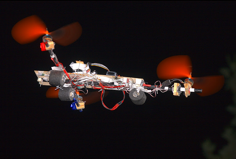
Made a program that spun Marcy 1 in a variety of throttle & cyclic settings, to measure the effect of cyclic on period. 

marcy1_period.png


Regardless of battery charge & battery weight, period for every throttle & cyclic had roughly the same curves.  Subsequent test runs got amazingly similar results.  The only thing affecting period was PWM.

That was subtracting cyclic from throttle to flatten the curve, but it did the opposite.  What seems to be happening is cyclic subtracting more throttle than it's adding which causes RPM to go down.

Then the throttle hits minimum on the subtracted side, but keeps adding cyclic on the added side, which causes RPM to go up.  Then we're hitting the limit on the active side & the inactive side for all greater cyclic, so RPM is constant.

marcy1_period02.png


Adding straight cyclic to straight throttle gave more consistent RPM curves.

marcy1_period03.png


Another algorithm which just subtracted exactly as much cyclic as it added, with the maximum determined by total throttle got pretty flat curves.


Even if we can't fly anywhere, the test jig did show some usefulness.  The next great task is making a test jig for altitude.


Then, there was this thing from many months ago.
 
kite01.jpg

kite02.jpg


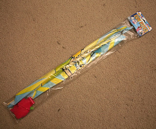
Thought it could be used as a super cheap airfoil in a monocopter.  It
would be limited to the smallest power system.  The torque would destroy it.  The motor would have to be mounted on it.  Extra weight would be required on the balance beam.

gui01.png
  Finally decided to move the GUI to C++ from Java.  Java is what makes money, but was real clunky & slow.  Java required a 188MB development kit on every computer we wanted to compile it on.
gui02.png
 Here, the C++ rewrite is on the right & the Java version is on the left.  The main difference is how Java uses a proportional font while C++ uses a fixed font, which looks much better.


Lowpass vs averaging notes


After 3 years involved in the subject, we now think averaging is a better deal than lowpass filtering.  Lowpass filtering is supposed to remove aliasing, but for all the talk of aliasing, let's consider the disadvantages.

The lowpass filter doesn't buy anything else except removing aliases.  A simple, 1st order lowpass filter is not going to chop off exactly at the nyquist frequency.  It needs to remove way below the nyquist frequency before all the aliases are truly gone.  Finally, it takes a lot of fixed point spagetti code if you want it to work fast, without an FPU.

The lowpass filtering we've used has probably not been as good as the averaging we used before.  It's probably caused more oscillation by increasing lag time than averaging caused by letting aliases pass through.

Having said that, the damping foam & ballast we use has allowed the lowpass filter to pass 1/8 its bandwidth in the roll & pitch direction, while passing 1/4 its bandwidth in the yaw direction.  That's just as good as averaging, so we're not inclined to change it.


145Mhz radio notes


Some ideas for a voltage controlled oscillator came to mind.  Basically, fabricate a multivibrator which can get in the 145Mhz range.  Feed a counter with it & have a microprocessor PWM the input voltage.  That might get close enough to use only a 256khz ADC.

Common transistors only get 2:1 gain at 150Mhz.  The counter would need a high voltage swing.  Just don't have enough instrumentation to test the thing.  Something could certainly be built in the 1Mhz range, just to test software radio.

What you want is the AD9552, a frequency up converter.  That can generate exactly 145.8Mhz for $14.  Nothing is cheap in this business.  Anything providing decent reception is going to be comparable to a $100 scanner.

This operation has little point.  The ISS broadcasts a repeating morse code beacon.  You'd get it for 30 minutes per orbit.  There was more point in the trapezoidian equatorial mount.  That produced images.

Read more…

Magnetometer again

akm8975_01.jpg


It turned out to be an 8975 instead of an 8973.  By some contact lens malfunction or erroneus Goog search, we thought it was an 8973 all year.   The 8975 has a completely different pinout than the 8973.  The power pins were shifted around.  An SPI interface was added.  The reset pin was removed.


The magnitude of the changes, number of revisions, & fact that it's used in the iPhone lead us to believe Steve personally required many minute changes of a cosmetic nature.

It was the chip in the iPhone 4.  It requires no external components.  It's not sold to private individuals, but it was free.

After banging on it for a while, finally caved in & built a 2 channel oscilloscope for USB.  It captures 2 channels at 130,000 samples/sec with DC coupling.  It can do a single channel at 260,000 samples/sec.  Much better than the soundcards we've been using for 10 years, but disappointing that 11 years of working didn't produce enough money for a proper oscilloscope.

That immediately showed our I2C was generating a 0 for the ACK where it should have been generating a 1 & the problem was solved.  Electronics are a lot easier with an oscilloscope.  The only other chip using I2C was the IDG3200, which didn't work in bulk transfer mode, so it ignored 0 ACKs.

We don't use hardware I2C unless the bandwidth requires it.  The restrictions on what pins to use are too severe.


Now another item which was delayed way too long.

hitec13.jpg

hitec14.jpg


It finally runs on USB instead of its own, always dead, NiCd.  It seems to work on just 5V instead of 9.6.  It turns out it uses the 9.6V to bias an LM324, which amplifies & lowpass filters the pots to 0-3.6V.  This op-amp has a pretty bad dropout voltage, so 5V is cutting it pretty close.

Making the transmitter run on USB was really needed for long duration bench tests.


vika1_19.jpg


All 8 degrees of freedom, GPS, & barometer reloaded.

vika1_20.jpg


All was as it was in July 2009, when we last flew with a magnetometer. Neither did it feel like the matter was making us fall in love with a golfing Air Force major, as we felt after July 2009.

Now we have attitude hold in manual mode.

vika1_21.jpg


Barometer was too close to the edge, making for less stable altitude.

vika1_22.jpg

vika1_23.jpg


Going with the pure gyros & no magnetometer was possible, but never the most stable.  This is the maximum stability.

vika1_24.jpg


Not going for automated takeoffs because we're broke.  Those caused a lot of crashes.  If anything doesn't work in an automated takeoff, it's gone.

That was it.  There's nothing yet to be discovered with Vika 1.  She's going to stay a standard autopilot.


The time for a real oscilloscope may be coming near, as we have dreams of custom software radio to receive the space station.  The current rig can get AM below 130khz.  Maybe a custom AM radio could overcome the urban environment barrier.

The way we see it, the great task in a custom space station receiver is making a 145Mhz local oscillator.  An alternative could be multiple conversions with readily available oscillators.  Do 1 with a 100Mhz, another with a 40Mhz, & another with a 5Mhz.  Sample the result with a 1Mhz ADC.

The other thing on our mind is launching something into space.  The way we see it, the most a private individual can afford to get over 62 miles up is a single bacteria or maybe something slightly larger.  Bacteria are manipulated using photonic pressure all the time, under a microscope.

The mane problems are detecting where the bacteria is, in order to aim the laser, & overcoming wind.  Bacteria can fluoresce or reflect the light of the manipulator beam.  This can be detected by a large enough telescope even if it can't be imaged.

The wind couldn't be overcome, so the manipulator beam would only be able to increase altitude, following it wherever the wind blew it.  Once high enough, the manipulator beam would be able to add horizontal velocity.

The only real benefit from this excercise would be to show the light received on a telescope was indeed from an object that you put in orbit. 

Read more…

Double cascaded RC filters

3689436105?profile=original

Spent a lot of time trying to low noise overclock audio preamps.  The main factor affecting you as you get an extremely high gain transducer into subterranian levels of noise is the power supply.  Every consumer gadget encounters some humming noise before it encounters thermal noise.  Even a DSLR has banding noise from a power supply ripple.

3689436126?profile=original

Power supply banding noise on an obsolete EOS 5D.


You would't believe how sensitive a primary microphone stage is to power supply noise.  Merely toggling a pin on a microcontroller or driving an LCD panel would cause enough ripple in the power supply to generate a hum.  2 hums of different frequency would mix & create a harmonic within human hearing.

The whole affair made us wonder if our obsolete sensors couldn't be improved with more power supply filtering.  Everything that makes money has loads of decoupling caps near each sensor, but we always flew with 1 cap for the entire autopilot & just the reference design caps for the sensors.

EEVBLOG's video on RC filters for smoothing PWM inspired us to look more at the subject.  More importantly, he showed a dual cascaded RC filter squashing the ripple more than anything else, which conflicted with our tradition of using the fewest components.  So we applied some RC filters to the king of noise: the SCP 1000.

3689436072?profile=original


It's an obsolete barometer, but it's all we can afford.  Tried 10ohm + 480uF, dual 10 ohm + 480uF, & 100ohm + 480uF.

3689436154?profile=original

The curves reflect the board cooling after soldering.  The noise decreased dramatically with the RC filter & is now in the 1/2 meter range.  The reference design obviously left a lot to be desired & a lot of noise is coming from the microcontroller itself.

The 100ohm + 480uF did slightly better than the dual 10 ohm.  So in matters of cost & weight, you're probably still better off leaving the dual cascaded RC filter at home.

3689436093?profile=original


Our obsolete GPS module wouldn't work at all with an RC power filter.  That has transients at too low a frequency to dampen out without an active regulator.  The barometer most certainly has its own transients, but still benefitted.

3689436148?profile=original

The gyros didn't benefit at all.  They're probably frequency dependant.  Left the cap on, to dampen vibration.

Maybe the transient voltages of polling a radio receiver can reduce its sensitivity?  Maybe using the interrupt pin on our 900Mhz radios would increase their sensitivity, but as soon as the 1st byte of data came in, the device would lose sensitivity for the rest of the packet, as we clocked out the data.  Maybe if we used the analog pin as a raw UART instead of the digital FIFO, it would be more sensitive.

Remarkable that 2 years later, radios haven't gone anywhere in terms of capability or parts.  There's been no major effort to go outside the 2.4Ghz band.

3689436177?profile=original


To our amazement, Ning now limits blog posts to 7 photos, so the rest are on blogger.  Everyone's cutting back on the freebees & firing everyone as the stock market booms.

vika1_14.jpg

vika1_15.jpg


Vika 1 flew again, after 1 year.  Her adhesive tape had settled with the propellers facing forward after all that time.  Round carbon fiber is unbreakable but impossible to build with.  The RC filter got the altitude much more stable, but heading without a magnetometer was worse than we remember.

vika1_16.jpg

vika1_17.jpg

vika1_18.jpg


Someone gave us an AKM8973 almost a year ago.  The datasheet seemed to have some errors in the pinout & it never did work.

Being a chronically unemployed programmer doesn't allow us to fly very often or buy the latest autopilot instead of hacking on the ghetto autopilot.  Actually pursued the LA aerospace idea for a year, but never got any interest.  The big thing these days for making money is making web applications with Ruby on Rails, but our analysis says it won't last any longer than J2EE.

Read more…

The quest for indoor flying areas

3689414153?profile=original


 Managed to get extremely tight XY position hold, with manual collective, no wind, & no attitude sensing.  There is a settling period, which is nowhere near stable enough to fly in the apartment.  The main requirement was large integrals.  The plot of the flight recording clearly shows where the camera was & how it detects sideways position much better than depth.


Visual attitude detection would need a tricolor LED & a lot of error correction.  The relative height of each color would determine attitude.  It probably wouldn't be fast enough to make a difference.

Altitude hold really needs a way to produce constant RPM for all cyclic.  Marcy 1 was making progress on altitude hold, when the cops showed up, hit us with the night sun, & ended 5 years of care free flying on the test range.

It takes thick skin to play this game.  Economies crumble.  Real estate loses value.  The wealth & status that bonds marriages is at the mercy of a few leaders.  Sitting still will never do.  Even sitting still, you need to fight for every minute you're alive, because as long as you're alive, you always have something someone else wants.

Somewhere, a bank is debating why someone should have a reduced mortgage principal, because one night, when his finances were keeping him up, he happened to notice some distracting UAV, 300 ft away, proof that the neighborhood was going to hell.

After 2 years of studdering progress, due to weather, we're at the point where 1 month in an indoor flying area would probably get the job done.


3689414133?profile=original


Read more…

WEBCAM WARS


3689413356?profile=original

Note that Marcy vision is our quadrotor's fuselage with a board from an
abandoned ground rover, complete with H bridges, servo headers, & a
900Mhz radio.


So the Logitec C510 has fixed exposure.  Search through the kernel for
V4L2_CID_EXPOSURE_AUTO.  Unfortunately, there's no way to manually set
the exposure & it picks a value which is too bright, but it does get
30fps.

Decided to see if locked exposure was possible on our other webcams &
sure enough, the oldest one, a ZStar ZC0301 cam, had a fixed gain
option.  It picks an exposure which just happens to work.  It could
track the LED in ambient light.  Its framerate could only reach 15fps.

Unfortunately, after all that hype, the shutter speed on all the cameras
in fixed exposure is too fast to get the continuous ring out of Marcy 1
the object tracker needs.  So fixed exposure without any adjustment
isn't very useful.

With the useless fixed exposure & the lack of clockcycles to process
1280x1024, the Logitec isn't the best camera & we blew $44.  For that
money, we could have built a 3D 640x480 camera.  Still forging ahead
with the Logitec because it cost money.

The Logitec was a squeeze play.  It was drastically reduced & we didn't
expect it to last.  The $16 webcams would probably have been better.
Maybe the CPU power to do object recognition at 1280x1024 will come,
someday.

There aren't many stories about how the iPhone is doing object
recognition.  It must have a hardware absdiff comparer & use very low
resolution images.

Well, highschool geometry applied to the imaging gets very good X, Y, Z
coordinates of the object.  The main problem is the weather.

3689413423?profile=original

Got separate servo mounts for every camera.

3689413328?profile=original

Swapped in the ZStar.

3689413377?profile=original

Tracking the LED with the Logitec.

The 1st campaign with machine vision was a real pain to set up & a
complete mess at tracking.  It locked on to the moon & lights.  The
servos jittered like crazy.  The weather was actually calm enough to get
some good data.  Spent most of the battery trying to get vision to lock
on to the vehicle.  A camera pair would definitely aid in separating out
the background.

The 2nd campaign went better.  Put in different PWM code for the camera
turret, which is very precise.  Pointed the camera at a dark area.  It
locked on the vehicle & never lost it.  Someday, the algorithm should
weed out ambient lights.

Never spent much time on PWM code, since it's obsolete, the real
solution is making all the servos & ESC's use I2C, & the fail safe modes
are real busters.  Suspect most people use a single timer & alarms for
the PWM loop.  It's noisy when 2 alarms get too close together.  For
camera pointing, a dedicated timer for each servo is required.

We could swap out the electronics for servos.  Developing ESC's is a lot
more complicated.  That takes over current detection, loss of signal
detection, stall timeouts, hand tuning back EMF voltage.

Camera turrets which automatically track objects are cool.  There's 1
more camera mount which could use some object recognition.

3689413444?profile=original

Made during the 1st period Major Marcy deleted us.  Always knew whatever
caused that judgement meant She would never see us in real life.
Indeed, She never talked to us in real life, had 6 suitors, broke up
with all of them, & moved away.  You were weighed, measured, & found
lacking before the 1st pitch.


Anyways, have some video of the 1st flights, from the camera turret. 

1st autopilot tests show real stability & real feedback to the machine
vision.  Marcy vision is producing better position information than
we've ever had before.

Tried 1 & 2 LED's.  1 LED at 3.3V worked just as well as 2.  Haven't
used chroma keying because it lowers the framerate, colors all saturate
to white on the camera, colors are less different from a black
background than white.

A camera turret made out of servos is way too expensive to ever be a
viable product.  If you could get it to recognize objects in daylight,
it could be a superior alternative to GPS.

The main question is how to track objects which don't spin & how to
handle ambient light.  We're looking at building databases of objects in
every possible angle & distance, with low resolution proxies,
compensating for differences in exposure, & using the 20MB OpenCV
library.

The only problem is the Goo Tube videos of OpenCV don't show the
accuracy we need.  Hard to believe the other machine vision guy died, a year ago.

With all the talk of balloon projected images rounding the blogs, maybe
sonar has a future in some future blimp which is small enough to fit in
the apartment.

Sleep schedule is pretty screwed up from flying the Marcy special in the
most stable, early morning hours, then spending hours wondering why our
flight controller didn't work.


Read more…

MACHINE VISION BEGINS

3689411988?profile=original


Since getting video into a computer is cheaper than ever, we've been
contemplating the idea of a cheap, turret mounted camera for position
tracking.  The sonar transducer is a huge source of weight & it doesn't
look like Marcy 1 will ever be stable enough to stay in sonar range.
The reduction in board size & transducer weight would pay off.

The optical mouse is proof that machine vision may replace all other
sensors.  They 1st appeared 25 years ago, requiring grid mousepads.
They barely worked, 10 years ago.  Today, they're taken for granted.

Machine vision would have to difference key out the background.  It
would have to measure X, Y, & Z from a single camera.  It would have to
be cheap enough to justify the means.

After playing around with different color keying algorithms, was pretty
confident position sensing could be done better with vision than sonar &
could be good enough to keep Marcy 1 in a box.  Ideally the camera would
be turret mounted, so that meant recycling a micro camera to build
confidence before investing any money.

3689411898?profile=original

This 6 year old laptop camera was never used. 

3689411942?profile=original

Really nice LCD, if only we could use it in a new laptop.

3689412010?profile=original

Just a standard USB cam.

3689412070?profile=original

Reinforced & soldered.

Unfortunately, these old cameras only do 4fps at 640x480.  320x240 in
complete darkness gets them up to 15fps.  The price goes up as frame
rate goes up.  Position sensing is going to be 1Hz, at most.

3689411947?profile=original

Finally caved in & got a Logitech C510 camera for only $40, locally.
Turns out the Logitech C510 actually goes up to 1280x1024 even though
it's only advertized at 1280x720.  No surprise why it was for sale &
discontinued.

In bright light, with minimum contrast, minimum brightness, 0
saturation, it'll actually hit 30fps at 1280x1024.  The reality is 15fps
is the most our simplest machine vision algorithm can process.

It spits out tons of bad frames on our desktop, but not on the laptop.
Lacking a way to disable auto exposure is a killer for machine vision.

The object of the game is to detect the center & size of an object.  The
only algorithm that seems to work, at a decent framerate, is luma keying
in a totally black room.  It's certainly good enough, since Marcy 1 can
only fly in total darkness, but developing in total darkness is hard &
we really want to fly other vehicles in daylight.

Flashing LED's would probably work, but Marcy 1 is constantly moving.

3689412031?profile=original

Don't turn it on.  Take it a apart.

3689412096?profile=original

The stand needs to go.

3689412168?profile=original

It definitely has the Auto Pilot look.

3689412202?profile=original

3689412181?profile=original

Focus is glued in place.

3689412120?profile=original

3689411988?profile=original

Put it on a pan/tilt platform to try to increase the field of view.  The
problem is it can't use difference keying, the servo movement is going to put a lot of noise

in the result.  A fisheye lens would be ideal.


Now we have video of the camera turret tracking the object, & how well
it tracks.  Marcy 1 got a 2nd LED to give the machine vision a bigger
target.  Even though the Logitech C510 can do 1280x1024, we found 640x480 to be

the most useful resolution with the turret. 


Discovered the brightness on the Logitech doesn't buy any more high end.  It
just clamps the white levels at lower values & reduces the size of the
JPG's.  If there was a way to lock the exposure, we'd be ecstatic.


Read more…

VIKA 1 RIDES AGAIN

3689410104?profile=original

The autopsy was finally done on Vika 1's final crash, on Sep 27, 2010.
No idea what caused the crash.  The best theory was mechanical failure
of the tail rotor servo horn.  The original theory was a lucky PWM glitch sending

the servo into a safe mode.


3689382286?profile=original

The final autonomous flight of Vika 1 was skywriting.  Then we took
manual control & she lost yaw control.

3689410126?profile=original

But the golf course finally had a rare sight:  An intact airframe after
nearly 14 minutes of flying.  The tail servo is cracked.  She has a new
computer which will probably need serious rework before full autopilot
returns.  Last year's configuration values, written by a much younger

lion, still worked.


A lot of work went into removing PWM glitches & powering down the

servo when not flying, to maximize life of the brushes.  Turning the pin to an input

doesn't work, because current leakage causes the servo to glitch.  It really needs a 0

level, which makes optimized PWM code a lot more complicated.


3689410097?profile=original

3689409926?profile=original

3689410148?profile=original

We've concluded the most valuable flight controller with today's
technology is not a full autopilot but a stabilizer.  GPS isn't cheap
enough to get the mm precision in the movies.  Energy storage isn't
cheap enough to have a fixed orientation platform in the sky.

MARCY 1 AIRFRAME WRAPUP

The Marcy 1 airframe seems to have converged on the most stable & efficient design.

3689410169?profile=original

Embry Riddle guy recommended replacing the winglet with dead weight. Put
2g of mass on the wing & the RPM decreased to the 250 range.  The weight
increased the angle of attack by weighing down the wing.  Started
installing sonar pieces.  Stability seems improved.  High winds have
dominated, except for 1 day a week.

There were a lot of parameters yet to be explored in last year's
design.  With the weight, she's very stable.  All our designs have been
stable with no cyclic, but the weighted wing is the most stable with
cyclic.  A bit surprising how stable such a low RPM could be.


Flight time with any battery is 11 minutes.  The damaged one may not be as

damaged as thought.


The throttle induced banking in enough wind can actually become too
steep & gimbal lock to produce serious oscillations. 


3689409948?profile=original

That's how the wing is fabricated.


The main problem is getting equal lift for all cyclic values.  A
constant throttle multiplier worked slightly.  Constant RPM when pulsing
the motor doesn't produce constant lift.


3689410213?profile=original

The sonar array was revived, a year later.  Surprised how well it
works inside.  We put a lot of energy into perfecting sonar.

3689410191?profile=original

3689410312?profile=original

Recall how this sonar array evolved, in a time before Major Marcy, 1000 years ago.

3689410262?profile=original

Decided the range was being reduced by the environment, so a conformal
coating was finally in order.

3689410244?profile=original

Most important is where the microphone connects to the 1st amplifier
stage.

3689410334?profile=original

There is a beauty in through hole soldering, even though it only goes in
the 1 Mhz range.

Sonar remains useless with this aircraft.  It could be the spinning, the
coning angle pointing the emitter sideways, or the wind destabilizing position too much.

3689410347?profile=original

Hole 13 was your best shot at an autonomous flight. It's the most wind
sheltered area.

Hole 13 definitely had no wind, but was too small.  Hole 11 is
definitely a hurricane.  Ran around the golf course for 90 minutes.

Radio is bulletproof, with the conformal coating.  The days of falling
out of the sky & smashing are over.  Every landing is under radio
control.


Finally, for the copter fans, it's a rare confluence of having an HD cam, the HD cam working, & an MD 902 landing near the HD cam.


Read more…

DEMO REEL, MORE MARCY1 DESIGNS


There's 1 big demo reel, containing highlights from the last 4 years.
Not nearly everything, but we got tired of editing.


In the process of researching the demo reel, found this oldie but goodie from 2007.

It was a 2 way data connection, using the
audio channel on a 2.4Ghz TV transmitter + a 72Mhz RC transmitter. We
already had this gear & didn't want to invest $80 in radio modems, so
spent most of that year on this problem. After making it work perfectly,
inside, it completely failed outside, so we spent the $80 anyways.


MARCY 1 FLIGHTS


A very short break in the weather allowed us to make some progress on Marcy 1 airframes.


2 years of studying monocopters has shown that no-one really knows how
they work.  Our most stable design spins at 300rpm, a wicked low speed,
has a huge coning angle, has wing pressure at the CG, & has a winglet.

Shrink the wing diameter & it gets unstable.  Reduce the RPM & it gets
unstable.

3689407738?profile=original
Decent one. 12 minutes of flight time on a dead battery. Balanced
wing pressure. CG in the lighest area. Horrible coning angle.

3689408020?profile=original

3689408059?profile=original

Most stable configuration ever. Flight time of 11 minutes on a dead battery. Very low RPM & very little oscillation. The winglet is the key.

3689408041?profile=original

When this comes floating down from the direction of your aircraft, it's
going to be one of those days. Definitely pushing the limits of
structural margins. She didn't get very far without it. Surprised how
important it is for stability.

3689408104?profile=original

Wind was howling for this one. Got a lot of oscillation when applying
cyclic, but it settled after releasing cyclic. Needs to be repaired
after every landing.  Coning angle may indeed have a limit, with
increased lift only being available from the inner diameter.

3689408125?profile=original

Weather closed off again, by the time this was built.  Got a few flights in, between wind gusts.  It didn't have any more landing damage & it seemed to be the most stable.  RPM was down to the 250 range.  Definitely getting to where weight is above optimum.


SPECULATION


Tying 3 monocopters together to make a super long duration VTOL has intrigued us.  It would need 3 batteries.  Motors that size are super expensive.  1 radio beacon would contain throttle for the 3
rotors, but they'd have to take turns broadcasting return packets with telemetry.


Then there's the issue of torque with 3 monocopters.  They don't make
enough torque to turn a quad rotor.  You'd need a big, heavy servo.

Also looked at coanda effect copters for Marcy 2.


Looking over coanda effect copters, people are obviously more interested
in the flying saucer shape than the efficiency.  We've been wondering if
3 couldn't be used to make a tri rotor more efficient.

Coanda saucers never made sense, because they use airflow from 1 surface
of the aircraft to pull up another surface, like a fishing pole pulling
itself up.  They deflect air horizontally & then deflect it vertically
again.  The extra lift is supposed to come from the propeller exhaust
inducing a flow in the ambient air.

They also need 1 more servo than a lift fan, to control yaw.


Read more…

Double blade disaster


3689399455?profile=original


Flew something for the 1st time since the PCS order. She didn't
oscillate, but didn't have enough power.  That design had no coning
angle.  Back to wing designs.


3689406711?profile=original

That had tons of lift, but no control.  The issue with flexible wings
pinching the takeoff pin was solved.  Got a pretty high coning angle.
Also saw very faint LED flickering.  Pitch oscillation was in full
attendance.  The optimum wing diameter for this motor is pretty long.
The lift relative to the balance beam inertia seemed too high.


3689406623?profile=original

Tried stiffer wings, but still got a coning angle.  Small weights on the
balance beam & wings didn't do anything.  RPM appeared too low for
stability.


3689406726?profile=original

3689406654?profile=original

3689406757?profile=original

Then, there was eliminating the coning angle.  With this design, we
noticed 1 wing always flew higher than the other, more dramatically than
any other design.  Every spin copter with a double wing was suffering
from blade tracking errors.  Blade tracking seemed to negate any
reduction in coning.


There's probably no way to completely fix blade tracking with such light weight,
home made wings.  It would take very precise angle of attack adjustment
on both wings.  It would have to be readjusted often.

A monocopter & all its inefficiency seems to be the only thing you can
make, without sophisticated mechanics.


3689406743?profile=original


We did finally discover CA glue desolver is really common acetone, for a
lot more money.  Wish we knew that, 10 years ago.

3689406814?profile=original


Read more…

QUEST FOR CONTROL

3689405567?profile=original

Put ghetto magnetometer on Marcy 1 because it only needs 3 wires.  Any I2C chip would need 4 wires.  The trick is moving it away from the motor in such a small aircraft.  Still amazing how sensitive such a small inductor can be, after trying to build one from scratch.


All roads lead to throttle controlled banking, with Marcy 1.  Been testing exclusively on
the test stand, because this airframe is going to disintegrate in flight
#1.  Still getting a disappointing amount of oscillation with 2 wings.
She only seems to want to bank in 3 directions.  Trim tabs get a slight
improvement.  The last segment has it finally banking in all 4 directions.

The future may be a very long balance beam & relatively small wings, but
it would give the slower RPM you need.  A future, high endurance craft
may have a 10' balance beam, 2' kite wings, actuators on the balance
beam, 4Ah battery in the middle.

After years of macros like (ROTORS == 4 && SERVOS == 3), finally decided
the easiest way to handle multiple, exotic aircraft is macros like
MARCY2, MARCY1.  Still, running 3 aircraft off the same code base is
like starting over every time you change aircraft.

After many projects based on shared code bases, we've concluded any cost
savings is a myth.  You're better off with different code bases.

We've never found an exit strategy from PIC.  Now that Atmel finally has
high speed USB, cost is the only factor.  Assembly language can't be
shared.  We've never learned how to drive a chip from an assembly
language listing.

All our batteries are stored at 32F to increase their lifespan &
increase the flight time.  Cryogenic propellant, you might say.  That
requires thermal stability in the electronics. 

Marcy 2 doesn't have a voltage regulator & the 1 thermally stable gyro
is ratiometric.  An LDO regulator would do it.  Doubt the gyro in the
S107 is stable enough to handle cryogenic propellant.

The quest for a stable yaw gyro began in 2009, when nose-in orbits would
throw off the gyro bias calculation & finish with uncontrolled spirals.
GPS heading was really limited in such small spaces.  There was no other
solution besides more stable gyros.

The DJI certainly does nose in orbits.  It looks like RTK.


For all the energy put into helicopters in the last 4 years, great
things have been achieved with common water bottles.  A 2 stage water
rocket can get over 400ft & release a parachute camera, all computer
controlled, for a lot less money.  The only problem is the downrange
clearance required.  We'd be stuck to 100ft anywhere in Calif*.


Also, in the super cheap department, where water is not available,
there's the rubber band powered glider.  That could get over 400ft.  The
best option remains a spin stabilized, vertical propeller booster of
some kind, with parachute recovery.


Read more…

DEATH OF THE ITG3200

3689400722?profile=original


The ITG3200 started its blog on good terms.  Turns out there's no deadband, but you get a level of 8 bit quantization when reading the analog results in I2C burst mode.


3689400699?profile=original


You have to read the analog results 1 byte at a time to get the full 16 bits.  Maybe to get burst mode to work, all the gyros have to be read at once, instead of just the Z axis.  Maybe you have to stand on your head.

Actually started noticing I2C anomalies when reading the low byte alone wouldn't work.  It only latched the 2 bytes when reading the high byte, as many microcontrollers do.  None of these anomalies are in the data sheet.

These are real traps for young players.  So now we have 6 ITG3200's which probably work & 1 which was probably fried, when we threw it across the room in anger.

On the bench, the awful temperature sensitivity from the IDG300 was still there.  Merely moving your hand near it shifts the 0 rate.  The ADXRS series is more stable by combining dual gyros.  It's a call between high stability & high price for robotics or low stability & low price for phones.

We still have delusions of succeeding the ADXRS by combining multiple, cheap gyros.  The temperatures are going to vary slightly & there's going to be cross axis coupling.


3689400743?profile=original

3689400870?profile=original

Line up the dots & you get 2 sets of gyros that oppose on all 3 axes.

3689400812?profile=original

The dual gyro test once again disappoints.  You're still better off using 1 gyro.  For very large temperature changes, they cancel each other out, but it's real coarse nulling.

3689400883?profile=original

Finally, a few temperature runs.  Nearly the same inconsistency as the IDG300.  You're looking at 3 bits of change on every run.  You still can't get the 0 rate from temperature & you still can't improve the accuracy by combining multiple gyros.


We did the same temperature tests with the IDG300, in June 2009.  There, we had 16 bits divided between 300 deg/sec.  The ITG3200 is dividing 16 bits between 2000 deg/sec, so the errors are numerically smaller, but probably equivalent in degrees/sec.


It's good enough to hold the heading for a 150 sec indoor flight.  It's good enough for a standard 9 DOF IMU fusion, but we still haven't found a cheaper replacement for the ADXRS150's on Vika 1.  Now Analog Devices has the ADXRS646 which, for $90, supposedly compares to fiber optic gyros.


3689400914?profile=original


It's a vintage model from 2007, but still the best.


DEATH OF SOFTWARE RTK GPS

Looking over the source code for rtklib & fastgps, you're going to have some doing to make an RTK base station out of that.  RTKlib has RTCM parsing, but nothing you could use to make RTCM packets out of the raw data.

Next, it's time to optimize fastgps.  Tried downsampling the baseband data to 4 megabits & it didn't work.

Next, tried skipping samples.  Skipping every other second of data killed it.  No way to do realtime processing by skipping samples.

RTK base stations for hobbyists are going to become standard, but whoever does it 1st is going to be in line with the uBlox price.  The LEA-6T is down to $180 + $40 shipping.


Read more…

Software GPS notes

3689400118?profile=originalThe main reason for software GPS is a cheap base station, generating RTCM messages to correct altitude measurements.  The aircraft would use a standard hardware module.

#1 the MAX2769 front end is just an analog to digital converter.  It outputs a 1 - 3 bits per sample, digitized form of whatever is on the carrier frequency.

There's no schematic or source code for the MAX2769.  1 datasheet has I0 used as a clock.  Another datasheet has I0 as a differential output.  Fortunately, it has some preset configurations.

You can gather from the presets & reference designs, that only the I1 pin in 1 bit CMOS logic mode & the CLKOUT pin are needed to make a receiver.

#2 the minimum output rate is 1 bit at 16 Mhz.

#3 that requires a high speed USB microcontroller, which mercifully started appearing in 2010, for $9.

#4 the GPS front end doesn't capture WAAS information, so you wouldn't get far with absolute waypoints.

There are many GPS libraries, but fastgps is the only one we've found, which inputs baseband data.

Fastgps is part of a book you probably need to buy to get very far with it.

Sample baseband data files & some changelogs are on http://www.gnssapplications.org/chapter5.html

The book's $139 tag undoubtedly covers bandwidth & quantitative easing.  It would be only $20 if the data files were compressed & houses were free.

The data format is 1 byte per sample.  Dividing the file size by 16367574 gives the total seconds recorded.  The example files use 2 bits per byte.  Bit 0 is always 1.  The 2 bits are left shifted 1.

Converting the file to 1 bit made no difference.  Here we have altitude from a sample file.


Here we have position.


3689400139?profile=original


We supplied the .sp3 file, which should have made more accurate readings, but this was an urban environment with only 6 satellites.  It gave the same result without the .sp3 file, so it's probably only speeding up initialization.


Fuggedabout downsampling it to 4 megabits.

Tracking just 8 satellites, our 3.6Ghz computer runs fastgps at 2/3 realtime.  Tracking 6 satellites, it's almost realtime.

That's without acquisition.  It would take a 4 core 3.6Ghz laptop to make a roving station.  Fortunately, the base station's job is a bit easier.  If the goal is just refining altitude, there may be a way to skip samples to make just enough readings for refining altitude.  The processing requirement has still put us off from software GPS.


Read more…

THE TRUTH ABOUT THE ITG3200

3689399270?profile=originalWell, to work in a spin stabilized mode, Marcy 2 would have to spin a
lot faster than a 3 channel coaxial copter can.  Without spin
stabilization, a $40 Syma S107 or a $25 Sky Invader didn't matter
because either way, we needed another gyro to know heading.  A 150
second flight time doesn't demand a very accurate gyro.

Mass produced Marcy 2's would use the cheapest single axis gyro
available, but suddenly a static proof bag of new gyros happened to
fall off a truck.  It's the ITG3200, another crazy small 0.5mm Invensense QFN. 

Decided to go ahead with it, to evaluate it for another 3 DOF IMU.  Have 5 years made

any difference with Invense gyros?


3689399198?profile=original


Unfortunately, it immediately showed a
large dead band, a convenient solution to the same old gremlin

of gyro 0 offsets drifting.  It automatically 0 centers itself, but it has to
rotate a large, minimum amount to detect anything.  You can rotate it
slowly enough, handheld, to go 90 deg without sensing anything.

It's intended for hand held motion sensing & gesture user interfaces,
not a heading hold gyro.  The deadband gets a lot

bigger as the lowpass bandwidth gets lower.

Direct analog pins would make this chip a lot more useful, but obviously
doing the samping on the die eliminated a lot of parts
that would be required for analog pins.


Through the IDG300, ADXRS150, LISY300, & ITG3200, gyros have gotten cheaper, but

they still use the same mechanism they did 5 years ago.  They can stack multiple gyros,

sample more bits, but the mechanism hasn't gotten any better.


UPDATE:


3689399348?profile=original

It wasn't a deadband as much as a mismatch between the lower & upper 8 bits.  It took a lot of rotation to get above 0.  Then the result was smooth from 0 - 255.  Then, it took a lot of rotation to get above 255.


It turned out the chip doesn't work in I2C burst mode.  You have to read the analog results 1 byte at a time.


MARCY 1

Read over the monocopter paper again, 2 years later, & figured out 3
factors affecting stability:

Wing pressure needs to go through the CG of the balance beam.

Coning angle needs to be minimal.

Balance beam needs maximum inertia.

The main advantage of a monocopter is having the most wing in the
fastest air for the least weight, but this results in a high coning
angle.  An ideal monocopter would have to be much bigger, have an IMU &
use servos for active stabilization.  The ideal, small vehicle is better
off eating the cost of a 2nd wing.

3689399361?profile=original

3689399284?profile=original

So the 2 flexing wings ended up pressing the fuselage onto the takeoff
rod & jamming it down.  Another problem was twisting of the angle of
attack to a level position.

3689399383?profile=original

3689399430?profile=original

It didn't have these problems in monocopter form, but we've also reduced
the wingspan & increased the RPM.

There's still hope for the lighter frame, if the design works & frees up
enough money for CF.  Time to dig out a tried & true brick frame.  It
was abandonned when we figured the monocopter was more optimum, but the
rigidity of balsa is really needed.


3689399455?profile=original


That definitely seemed to be more stable than the monocopter, but led us back to the actuator problem.


Read more…

Stop motion excitement & LCD drivers

Got some high speed photographs of Marcy 1 spinning at flight speed, to see if the actuator & the wing did anything.   A slow motion video cam would be nice.


3689398170?profile=original


3689398311?profile=original

3689398256?profile=original

3689398183?profile=original


The idea was to make a wing which would be pressed up into an actuator
by the airflow, but there was no way to see if it was pressing up
without high speed photography.  It definitely converges on a natural
angle at which She takes off.  The actuator needs to go slightly steeper
than that, to accommodate water loads.  Maybe the hinge tape was keeping
it from pressing up.


It was less like hinge tape & more like kite string.  The wing was
free hanging off the spar & still lifting the fuselage. There was an
oscillation in the wing angle. 

3689398326?profile=original

3689398278?profile=original

3689398354?profile=original


Next, came a paraglider concept, with extreme turbulance.  There is a
limit to the hang distance.  The free hanging wing solved a lot of
problems, regardless of its actuateability.  Its own weight turns it
into an airfoil.


3689398292?profile=original

3689398349?profile=original

3689398375?profile=original

3689398463?profile=original

Finally arrived at a wing with actuator, where the air flow was enough to restore its angle.


3689398414?profile=original

3689398478?profile=original

Finally, the wing actuator came on, the wing moved slightly, & nothing happened.  There was no rolling, no lift, no nothing.


3689398435?profile=original

3689398507?profile=original

Another control surface behind the propeller didn't have enough thrust to overcome the airflow, at all. 


It's getting closer to a heavy, brushed servo.  How about a home made LCD driver, instead.  A way to display data for $1 would be real useful for the credit challenged.


3689398390?profile=original

Took interest in using these $1 LCD panels to display data.


3689398554?profile=original


3689398528?profile=original


They have 4 ground planes, connected to all segments, & 10 wires connected to half of each digit.  They're wired in such a way that any single segment can be lit by a combination of ground plane & half digit.


Driving LCD panels with bare voltages is a bit harder than sending commands to a UART.  We reverse engineered the waveform, since The Goog had nothing on it.


3689398577?profile=original


The 4 common plane pins are pulsed at -1.5V or 1.5V when they're active, & 0V when they're inactive.  A charge pump is used to get -1.5V & it ripples.  0V is the off voltage.  The frequency is 32Hz.  The 1st half of the period has 1 pulse for each plane at 1.5V.  The 2nd half has 1 pulse at -1.5V.

The digit pins are always -1.5 or 1.5V.  Looks like there's a maximum voltage difference which doesn't turn on the segments.  Pulse the opposite voltage of the active plane to turn on the segment.  Pulse the same voltage as the active plane to turn off the segment, but since the inactive planes are all 0V & within the maximum off voltage, they don't turn on.


The easiest route for us was using a voltage divider to get 1.5V & making the planes 0V or 3.3V for on & 1.5V for off.


3689398603?profile=original

The panel could actually be driven with only 0V & 3.3V, but it wouldn't work in sunlight.  Either the UV light or the heat turns on all the segments.  This alternating current with 3 voltages is how all passive matrix LCD panels work, but everything from the earliest 1970's watch to the newest LED backlit phone uses alternating current in some form.


Read more…

Dean burn #2

For the 2nd time, we plugged the genderless micro Dean connectors in the wrong way & got an explosion followed by fire.


3689397741?profile=original

Without any gender, many a modeler has plugged 2 batteries into each other with these connectors, but why would anyone except a complete idiot say anything bad about a connector they spent $5 on?  Well, let us be the 1st complete idiot & regale the world with this new revelation.


3689397854?profile=original


3689397783?profile=original


3689397876?profile=original


This time, we got a pretty nasty burn.  The micro Dean connectors are the best connector for the job, but the lack of gender makes them Satan.  Marcy 1 has a new objective: finding a better micro connector.


Read more…
3689396548?profile=originalDecided to fly with the photodiode azimuth sensing & it was a disaster, as expected. It reminds us of the years spent on Heroine 2200's photodiodes, trying to figure out a way to intelligently detect the start of a period.


Detecting the period was hard.  Fast fourier transform needed much more cycles than our flight time.

The best result was by testing all the possible periods on the last 1024 samples.  Take the period which has the most similar repetitions.  Get the maximum signal in the last period.  Get the time of the maximum signal relative to the time of the current sample.  The problem was when the most similar repetition was actually a region of 2 periods.


Next, it was an IR LED on the ground & the IR receiver from our 5 year old Picco Z in the air.  That would not detect ambient IR.  The problem was the receiver is digital.  It would detect reflected IR from random surfaces & output the same level as the incident signal.

Finally came the poor lion's machine vision.  Have an IR emitter on the copter & an analog IR receiver on the ground.  That didn't detect enough of a difference from the abient IR.  It would take some massive circuitry to get an analog IR receiver at 38khz.

All roads led back to the magnetometer.

HOW MAGNETOMETERS WORK

3689396622?profile=original

3689396593?profile=original

3689396669?profile=original

3689396690?profile=original

3689396720?profile=original

3689396761?profile=original


pnicorp.com actually has the theory of operation of the Micromag 3, so we ripped off a sensor from our Micromag 3 & built a more compact magnetometer, to avoid spending $40 & waiting 2 weeks.


The Micromag 3 has a 600uH inductor, biased by 2 47 ohm resistors.  It measures the amount of time required for the inductor voltage to cross a certain threshold after alternating the 2 bias voltages.  The inductance changes, depending on the amount of magnetic flux.  It uses a standard microcontroller, not a custom ASIC.

The 1st thing you notice is normal inductors don't work.  You need a core which is a lot more sensitive to ambient flux.  The inductors in magnetometers use a thin film permalloy.

The 2nd thing you notice is the inductor saturates very easily, from a NdFeB magnet.  Readings make sense until the magnet gets too close.  Then it reports no flux, as its core is saturated.

The final trick is the reference voltage for the comparator is very important.  Ours had to be exactly 1.0V.  1.1V or 0.9V didn't show any response to ambient flux.  The inductor voltage only got to 1.4V & there was an optimum point in the waveform to detect flux variations.

To keep the inductor from becoming permanently gaussed, they use 2 comparators & alternate the polarity.  Since we're just interested in a binary result, we use 1 comparator.  It puts out a really faint signal.  Micromag 3 stacks hundreds of readings to get more sensitivity.

The CPU on Marcy 2 actually has 2 voltage references, allowing us to test the battery against a fixed voltage & test the mag against a ratiometric voltage, but even then, the ratiometric voltage needs tweeking for every flight.

This would all be easier with a hall effect sensor & an instrumentation amplifier, luxuries beyond our useful payload.

3689396643?profile=original

Got a standard azimuth waveform on a flight without any cyclic control.  Not as strong as the original Micromag 3, but think about the parts count.

3689396743?profile=original

As soon as cyclic was enabled, things fell apart.  1st of all, there's a lot of offset from having the motors & electronics in such a small space.

Secondly, the pulses from the tail rotor disturb the attitude enough to throw off the magnetometer waveform.  You get 1 pulse, then the tail rotor goes crazy for a while.  With such rapid attitude changes, zero crossings are no longer enough.  Time for derivatives.

3689396865?profile=original

That was a complete 150 second flight.  The derivative got us back to a centered waveform with clear 0 crossings.  That nailed the azimuth every time.  For the 1st time, we finally had enough cyclic control to hover something in the apartment, which introduced another problem.


The oscillation from Marcy 1 came back.  Pulsing the tail rotor started the same oscillation & the tail rotor wasn't fast enough to stomp it out.  Pulsing any spinning airframe just makes it swing like a pendulum.

Finally caved in & added weight.  The vertical flap actually did improve matters slightly, but now the tail rotor's slow response showed.  The blades on this copter have already run their course.

Set the tail rotor to always be on, which should have reduced the spinup time, but mainly decreased the difference between on & off.  It definitely appears as if some filtering is interfering with the tail rotor commands.  The main problem is the oscillation.  The functioning tail rotor, flybar, counter rotation & vertical flap didn't add any more control than the bare Marcy 1.


Read more…

IR protocols & U

3689395970?profile=originalMarcy 1 actuator notes

So we tried making the actuator pull the flap instead of push it.  This made gravity the restoring force instead of air.  Maybe it wouldn't need as much power & could stay on full time.  FUGGEDABOUTIT.  It needed just as much power & quickly overheated.  Your best option is a pushing actuator.


Things went better with Marcy 2.  Payload test showed she probably could lift the Marcy 2 electronics package.  Now the IR protocol.


3689396002?profile=original


Inactive high.
960 bits/sec
start bit is 1/270 seconds low, followed by 1/1000 high
each bit is 1/960 seconds, beginning with a fall
1 bit is low for 1/2400 seconds
0 bit is low for 1/1200 seconds
1/40 seconds high between packets


From Darkstar2000's work on the obsolete 6020, we have the protocol:

http://www.rcgroups.com/forums/showthread.php?t=1231421&highlight=s107+protocol&page=2

8 bits: throttle 0 - 127
4 bits: yaw 0 - 15
4 bits: pitch 0 - 15
1 bit: left yaw if 1
1 bit: nose up if 1
1 bit: yaw trim left if 1
5 bits: yaw trim
2 bits: 11 for channel A
6 bits: chksum (sum of 1st 3 bytes + 0xf) & 0x3f
1 bit: 1


It transmits packets more frequently during a change.  Fortunately, Darkstar2000 also reverse engineered the S107, so changing protocols won't be a complete disaster.  Exactly why he did all this work is a mystery.


3689395991?profile=original


3689396011?profile=original

Next comes a new Marcy 2 board for azimuth sensing & sonar on only 3.7V.  It's pretty aggressively weight minimized.


3689395945?profile=original

3689396063?profile=original

3689396119?profile=original
Converting it to 900mhz was a no brainer.  Mounting the board for flight was a nightmare.  Servo connector or soldering?  Enough power in the flight battery to test the board?  Can you justify the weight of a servo connector or an aux power source + diode?  2 pin + permanently soldered data connection or 3 pin connector?  Eventually, it came to a 3 pin servo connector.


3689396076?profile=original


3689396098?profile=original
Our 1st flight test of a photodiode as azimuth sensor, indeed the world's 1st flight, was disappointing.  The signal had so many peaks, it would take herculean processing to convert it to a period & phase.  It would have to be flown with a single light source, at night.


Read more…

Marcy 1 actuator development


Now, development of an actuator for Marcy 1.  After all that static testing against gravity, the restoring force from the air wasn't enough to get the flap to straighten.  She just cocked up like a wing at 45 deg.

Since air exerts less force than gravity, maybe actuating the entire wing with some kind of spring as a restoring force isn't too crazy.


With Vika 1, we had low voltage transients, due to CPU usage at 40Mhz, sending the flight computer into reset.  Brown out voltage of 4.6 was making it reset.  Set it lower & it started working.


Did the same brown out voltage change to a Marcy 2 board we had since 2010 & it also started working.  That board was dead on arrival, last year.  Showed it during interviews & carried it around in luggage, not fearing it being destroyed by man handling, knowing it was dead.  Who knew it actually worked.  The Marcy spirit can't be destroyed.

The goal with the Marcy 2 board is now an autopilot for a cheap, 3 Ch copter, just to demo sonar.  Since these copters only go forwards & backwards, they basically have to constantly turn towards the waypoint & fly towards it.  Real workout for detecting heading.

Since they're extremely weight limited & have a limited number of flights before the brushed motors die, that means leaving it untouched. The best way into the controls is to bypass the receiver's IR signal with our own & use our own remote control.


3689394914?profile=original


There it is.  The $25 pink special everyone on RCGroups raves about.  $3 tax.

3689394860?profile=original

What's not discussed on RCGroups.

3689394882?profile=original3689394937?profile=original

It should be passively stable because it's a counter rotater.

FUGGEDABOUTIT.  It doesn't have a gyro, so it spins & spins.  The controls have a serious lag.  It's no more dynamically stable than a Picco Z.  Forget about hovering over a waypoint.  The control lag kills any chance of substituting a gyro.

So what about letting it spin & using the tail rotor as a cyclic.  The pink copter has a lot more payload than the Picco Z.  It has a 150mAh battery.  To keep the demo under budget, we're back to a photodiode azimuth sensor.


The easiest sonar demo is a Sumo robot of some kind, that roves in a 10x10 ft area.  Even better, make it solar powered.


Read more…

Actuator excitement


3689393275?profile=original

3689393315?profile=original

3689393042?profile=original

3689393337?profile=original


Finally caved in & built a traditional rotating actuator.  Didn't like
the weight or complexity of these, but they're the only way to keep the
distance between coil & magnet constant throughout the motion.  Having a
minimal distance between coil & magnet is where the maximum force comes
from.

The test article was made from balsa.  Medical tape once again came in
to shield the mechanical shaft from the wire.  It has 3x more wire than
actuator #1.

It certainly caused a lot more motion, but yet again, not enough force
for a full wing actuator.  Forget about moving the entire wing in our
mass budget.  Variable pitch is out.  It can move a 1" x 13" x 1/16"
flap against gravity, for a short time.  It might work in a ducted fan
VTOL.

3689393355?profile=original

3689393408?profile=original

3689393368?profile=original


Next, another solenoid with the 1" flap.  Pretty good deflection with
this one.  Quite an alignment problem.  The permanent magnet needs to be
halfway down the solenoid to get the most thrust.  Any lower & it's
attracted downward.  Any higher & it's not deflected as far.  This leads
to a gnarly wing stand.

Really disappointing to not be able to move the entire wing, but that's
why we don't have variable pitch wings on airliners.

Thus begins another round of solenoid tests with 1" flaps & another $2
of magnets.  A vi ate ing does suck money even without any flying.

3689393429?profile=original

Efforts continue on improving radio weather resistance with
polyeurethane.

3689393389?profile=original

The 900Mhz Marcy 1 ground station sees daylight again.

3689393443?profile=original

Marcy 1 flight computer, covered in dust, insects, & polyeurethane.

3689393296?profile=original

New wing attachment required some fancy woodworking.

3689393517?profile=original

Didn't like this wing attachment, but it was the only way.

3689393552?profile=original

To fit the solenoid in.  We do not claim any crash resistence.

3689393465?profile=original

3689393573?profile=original

3689393486?profile=original

3689393538?profile=original

This one stayed up for 6 seconds at 3.3V before the TO-220 voltage
regulator fell over.  With this kind of Amp suckage, you're not likely
to get an increase in lift without a decrease in motor output.  Next
comes making a more efficient actuator.

3689393594?profile=original

Straight from RCGroups lore, it's CA glued pieces of plastic.

3689393609?profile=original

3689393630?profile=original

3689393665?profile=original

This 4ohm 4g monster held for 10 seconds at 3V.  It even actuates at
2V.  With BJT + magnets, it probably weighs over 6g.  BJT's serve us better than

MOSFETs because they can handle back EMF.


The smallest servo is the GWS Pico, weighing 5.4g.  That could move the
entire wing, but burns out quickly.  The only other redeeming quality of
actuators is the price.


The main drag on this operation is the fact that actuating the wing is going

to suck a lot of power.


3689393703?profile=original

Next, in the Marcy 1 weight reduction department, it's spray paint
stenciling.  That was real unpleasant to carve out.

3689393643?profile=original

3689393679?profile=original

It's very inconsistent.  We have many wings yet to crash.  Should have used
transparency instead of paper.  The lighter the spraying, the better.  1 pass is all it can handle

before it bleeds.


3689393717?profile=original

A new board for Vika 1 started.

3689393764?profile=original

This one's intended to minimize GPS interference.  It has a shielded
oscillator at 40Mhz.  40Mhz is the dead zone.  It was the 1st Vika 1
board we ever laid out.  It was laid out in 2009, before Major Marcy, & before

we were confident in crystals.

3689393730?profile=original

There's nothing new in it.  Once again, forgot to put the GPS voltage
converter on it, provide enough pins for everything, provide capacitor
pins.


It's exactly 1 year to the day since the 1 & only time Major Marcy said anything to
us in real life.


It's a dark anniversary.  Now that 1 year has passed, it really is
final.  There was a bet whether we'd ever be in a photo with Her.
Mathematically, it seemed likely, 1 year ago.  It never happened. 


While She was very reclusive, only associating with a handful of people in real life,

was really freaked out by men who didn't demonstrate traditional male dominance,

it was the laying of a very negative judgment on our work to have a heroine Air Force

Major want nothing to do with us.


Read more…

The 'copter


Now we come to proposed improvements in Marcy 1.  Fired up Her avionics & got the radio to work again.  That was a huge step, but there's a long road of depression between this & golf course flight.

Most micro airplanes have a solenoid actuator for the rudder on the fuselage & no aileron actuator.  We need the aileron actuator, which begs the question of how such a large surface can be actuated from the fuselage.  It would be on the fuselage.

Fabricating a traditional actuator without machine tools is quite challenging.  A material stronger than wood, yet bonding to CA glue is needed.  It has the disadvantage of deflecting a large wing surface.

The leading idea is to make the whole wing 1 big actuator.  The repulsion between a NdFeB magnet on the wing & a coil on the fuselage deflects it downward.  Airflow centers it.  This is rugged, light, & uses the full surface.  The same principle could be applied to a lift fan if it was bidirectional.


3689392513?profile=original


3689392534?profile=original


Next, the actuator department came up with this.  Not enough power to
get any motion before it overheats.  At 3V, it moves the wing 1/4" &
then dies.  That's 3A, almost the motor at full power.  At least we now
know medical tape sticks to wood & makes viable hinges.

Without a core, the solenoid isn't going to produce much thrust.
Conventional actuators are ruled out.  It takes a ton of force to move
the wing, compared to a normal micro plane.  It takes our largest NdFeB
magnet to fully deflect the wing.


3689392556?profile=original

The ideal Marcy-1 is variable pitch & fixed RPM, as we learned before.
The best any useful weight is going to do is variable RPM & the minimum
actuation.  1 option is a solenoid core.  There's also a linear motor
with multiple solenoids.


1 search for actuators leads to another thing.

No, we are not trying to get a marrital tax deduction without a providing for a wife 1/2 our age. Homopolar motors looked like a novel way to get miniature thrust. The problem is fabricating bearings precise enough to reach enough RPM & attaching a propeller tight enough for VTOL.

Figured we'd make a high quality video of a homopolar motor, since all the others are out of focus. Those things are really tough to balance. See video above. Music: Transformers escape


Read more…