All Posts (14048)

Sort by

Its now been a whole year since I got addicted to the crazy hobby of Autopilots.

What a wild ride!!!

There has been some fantastic moments and some of total frustration, but it has been an exciting and rewarding journey.
There are a lot of people who ask about getting into the hobby and have somewhat ambitious ideas about building a drone to do X and Y before they have even completed their first flight.
This is a short video compiled from some of my mishaps over the last year that hopefully helps show those considering getting into the hobby why it is an extremely good idea to start small and cheap and gradually work your way up to more ambitious goals.

When I started, I was a relatively competent RC pilot. All of the crashes and incidents in this footage have arisen from me making stupid mistakes on the Autopilot side.

By setting the wrong waypoints and RTL'ing straight into a tree, by setting my altitude wrong, by trying to do PID tuning while in the Air, by putting too much weight on a plane and it not getting off the ground and hitting a tree etc etc.


All in all, the crashes when compared to the number of great flights have been relatively few, looking back at the log I've kept, I've flown 165 individual flights in the last year, with a combined total of 95 hours in the air.

These have primarily been logged on one of the 3 SkyFuns I have built and destroyed in that time.

The first one only lasted 5 flights, the next one I got 36 flights out of and the last one is still going strong.

I've now progressed onto a composite FPV168 and also a Hugin (which you can see being destroyed in the last clip with too much weight to get off the ground).


Over the next year, I'm planning to get the new Skywalker X8 and perfect Telemetry and video over a cellular link which I have been experimenting with more recently.

Best of luck to you all, and hopefully this video serves as a lesson in what to avoid doing and saves you the time / expense yourself.


Read more…

ArduWot returns to flight, Simulink in control

2011 didn't end too well for the ArduWot, incorrectly fitted undercarriage made for instant nose over on throttle up which broke the prop and fried the ESC. A new ESC arrived Monday which was quickly fitted only to reveal it to be useless at powering the aircraft and APM, luckily we'd also ordered a BEC (for a different project, but ArduWot takes precedence!). With the ESC and BEC fitted we took her out for a shakedown flight which went without drama, only point of note was a noticeable shift forward in CG with the addition of the BEC. Some advantages of the BEC are some nice little battery monitor lights and a switch for APM/RC gear. The switch is particularly useful as powering up the aircraft in a level attitude (hard enough for a tail dragger) by connnecting the battery in a cramped battery bay used to be quite fiddly!

3689440525?profile=originalBattery monitor lights

3689440541?profile=originalCramped battery bay with switch

Next flight it was time to put Simulink in control. Our last attempt at this went straight to a closed loop heading hold system, but this approach makes it hard to quantify the performance of individual subsystems (namely the delay in the ZigBee link). So this time we started off with some simple open loop step tests. Simulink was given full attitude and throttle command with the defaults being zero roll and pitch and full throttle (as it was a fairly windy day). In the first test a pitch step of 0.75 radians (~43 degrees) was commanded which ArduWot attempted admirably but fell short by a few degrees due to a lack of power. Second test was a 0.5 radians (~29 degrees) roll step, despite the gusty wind ArduWot managed to maintain this perfectly.

Both tests were plagued with Zigbee connection issues which is down to a combination of poor antennae and a restricted operating area. We are forced to operate fairly high and pretty much over our heads dues to high trees all around, this is not the best place to be when you have a pair of omni antenna mounted vertically. We're in the process of knocking up a tracking rig for a high gain directional Yagi antenna which we hope will help matters. When we do lose Zigbee connection for more than 1.5s, APM goes back to it's "Auto" mode. You can see this in the roll test video when ArduWot rolls level and begins to descend, this is it going back to it's default mission which is to fly a circuit around our test site but as soon as it picks up Zigbee again it goes back to Simulinks command.

Despite the telemetry issues we've demonstrated the viability of closed loop control using Simulink. The pitch test saw Zigbee drop out just at the wrong time to properly assess the delay, but the roll test shows a round trip delay of 0.3s which is more than adequate for outer loop control.

The current status of our code is very much preliminary (proof of concept), so it's not very well written. However if anyone is interested there is more information on our wiki, including a link to download our Simulink and modified APM code.

We've just set up a SIL testbed (soon to be HIL also) which should speed up our development and we hope to have some fancy algorithms running in Simulink and other external code running in the coming months. As this happens I'll keep you guys updated!

Read more…

Motor Efficiency

I recently saw a post regarding propeller quality and I figured I would contribute my motor-selection knowledge as a nice complimentary post.

This is my first post, so a quick intro.  I'm an electrical design engineer for BLDC drives, known in the RC community as ESC's.  Most of our applications involve fans and pumps, so there is a lot of similarity in what I do in my day job and what you all are doing here.  I found DIY Drones a few months ago and I now catch it nearly every day looking for something interesting.  I always find something :).  I will be doing my first UAV soon with the standard (for many of you) Bixler drone.  It is on its way :).

3_p1180115251151.png

Now, to my topic.  Above, I have a very typical series of curves (credit to these guys for the chart).  These curves are generated by applying a constant input voltage to the motor and ramping the torque from 0 oz-in to locked-rotor.

There are two ways to choose a motor.  For performance, you would want to look at the power vs. torque (dotted red).  In this case, you would want to choose a prop that places about 0.325 oz-in of torque in order to maximize the power output of the motor.

The second way to choose a motor, which applies more to drones, is to look at the efficiency curve and to select a motor/prop combination that puts you just to the right of the peak efficiency point.  In this case, a load of about 0.1 oz-in would be ideal.  If you select a point to the left of the peak, even light variations in load will cause vast efficiency swings (notice the steep slope) and if you select a point too far to the right, then you will be losing power continually with little recourse.

One more thing.  If the voltage (PWM duty cycle) is reduced, these curves also scale to the left.  The scaling isn't perfectly linear, but it is close enough for estimation purposes.  Also, your propeller draws torque in a very non-linear fashion (vs. speed).  It is *very* likely that your max efficiency point with a particular motor/prop combination is not at maximum throttle, but at some other point.  So you might need to do some testing on your current setup to find out where you are and go from there.

It is likely that you don't have a dynamometer (test equipment that records torque and speed by applying a load to a running motor).  I certainly don't, but I do know that there are ways to make a DIY version.  Most motors on the market have a torque/speed curve like the one above, or maybe enough data that you can generate a rough estimate and draw a graph using Excel or LibreOffice.  Basically, torque/speed curves are attainable from the manufacturer.

The prop is a different story.  Each prop does have a typical torque applied to the motor vs. the prop speed... but I can't seem to find one.  This might be b/c a prop behaves differently at standstill and while moving, but it would still be nice to have a starting point.  The ideal way to get this would be to get a torque transducer and simply run the prop through its speed range.  Unfortunately, that is expensive.  This is where our motor torque/speed curve comes in again.  Note that one of the curves is current vs. torque (blue).  You should be able to measure the DC current draw of the motor and get an idea of the actual torque being applied to the motor shaft.  It would be best to take this measurement in-flight, but a static thrust shouldn't be too far off the mark.  Remember to keep the voltage steady at the voltage at which the curve was taken.  These curves are only valid at one particular voltage!

Now that you have the torque, go vertically on the chart to the motor efficiency to see where you are on the efficiency curve.  At 100% throttle, the ideal point is just to the right of the peak efficiency for maximum endurance or the peak power point for a performance or aerobatic design.  Or you might decide that you want to run at some other operating point for most of your flight, in which case, you would want to choose a motor/prop combination that puts you in that sweet spot.  I would stress that you want to be just to the right of the peak.  To the right of the peak, efficiency drops off slowly, so a small error won't cause a big loss.  To the left of the peak it drops off very steeply.  Manufacturing variations, measurement errors, etc. will likely add uncertainty to your data, so be sure to stay in the safe zone rather than on the edge of the cliff.

There are loads more to this.  People have written PhD's on several of the topics touched here and my knowledge only scratches the surface, however, this should help you make a more informed motor/prop selection.

Good luck,

J

Read more…
An Aeryon Scout, a four-propeller unmanned aerial vehicle, returns to Nome on Monday, Jan. 9, 2012, after surveying the sea ice near the town s harbor. University of Alaska Fairbanks researchers from the Geophysical Institute arrived in Nome to prepare for the arrival of the Russian fuel tanker, Renda. Jessica Cherry photo
An Aeryon Scout, a four-propeller unmanned aerial vehicle, returns to Nome on Monday, Jan. 9, 2012, after surveying the sea ice near the town's harbor. University of Alaska Fairbanks researchers from the Geophysical Institute arrived in Nome to prepare for the arrival of the Russian fuel tanker, Renda. Jessica Cherry photo

Read more: Fairbanks Daily News-Miner 

http://newsminer.com/bookmark/17062606

Read more…

SparkFun Free Day!

When/where: 9:00 am MST Sparkfun.com

What: Win $100 of a total $200,000 giveaway

"Well the time is near - tomorrow at 9 AM Mountain Time, SparkFun is hosting the third edition of Free Day. This year we are giving away $200,000 worth of $100 credits to the SparkFun website. Show up here at 9 AM Mountain Time on January 11th, 2012 to try your hand at winning! Want to know more? Watch the video below:

Here's a little more information:

The Rules: The give away starts at 9AM MST and is limited to $100 per person. Each winner will get a gift code that can be used at SparkFun within 60 days.

Stipulations: In order to participate, you must register an account on sparkfun.com, and use a modern browser with JavaScript and cookies enabled. (Sorry, Lynx!)

The System: We're doing away with the quiz system of 2011 and trying to return to a give-away system that is as simple as possible, but can handle the load of the Free Day crowd. The system will randomly give away the 2,000 gift codes (2000 * $100 = $200,000) throughout the day. For example, if we set up a 7 hour giveaway window, we should see a gift given away about every 12 seconds. We will allow people to try for the prize as many times as they'd like, but we will have a basic system to prove you're not a script.

Free Day is always an intense and interesting time! We wish all of you the best of luck in getting your share of the prize! See you tomorrow!"


Read more…

Turnigy G10 Outrunner - Hair Dryer & Thrust test


Motor: Turnigy G10 810kv
(http://www.hobbyking.com/hobbyking/store/uh_viewItem.asp?idProduct=19020)

ESC: Turnigy dlux 55A SBEC
(http://www.hobbyking.com/hobbyking/store/__16365__Turnigy_dlux_55A_SBEC_Brushless_Speed_Controller.html)

Battery: Turnigy Nano-tech 5000mah 4S1P
(http://www.hobbyking.com/hobbyking/store/__17254__Turnigy_nano_tech_5000mah_4S_35_70C_Lipo_Pack.html)

Prop: EPP1245 CF SF
(http://mikrokopter.altigator.com/propeller-pair-epp1245-cf-p-89.html)


I was expecting around 1.6kg of thrust per motor. My platform weighs about 5-6kg.
1.6 x 8 = 12.8kg for a 6kg platform is fine. With a 12x45 prop, im getting 2.4kg per motor.
I think I might have to add some weaponry or perhaps build a small cockpit for my cat!


Thanks to Karla for allowing me to test the "blow your hair back" factor.


G:)

Read more…

The Relevance of Propellers

Hi again. Latelly I've been testing some different propellers on my quad and checking the main differences between them. For my emax gt 2218 930kv , my 3S batt and the 1500 / 1600 weight, I was using those cheap 12x4.5 props. I even bought 12 pairs for $25 or so, and one thing I can tell you about them... FORGET ABOUT IT. After 2 crashes from wich I could not tell if it was a motor or prop problem, I decided to test other props. I started thinking that too much flexibility would have a negative impact, both on material resistance after a couple of flights and prop deformation on higher RPMs giving it less efficiency.

Looking close to one of those cheap props with about 3 flights, I noticed the plastic was becoming fragile near the joint to the hub (becoming white as if it was heavily bended). At APC page you can read about the forces involved and afecting a prop, so I decided to start using higher quality and stiffer props, and I'm not regreted.

There are some models wich mix carbon with nylon giving it a good stiffness. I'm using composite APC E series and APC slowfly and also those carbon nylon ones and all seem to behave very well.

One thing you will be noticing is the much quieter noise and less vibration you get from the motors. Balancing is almost unnecessary, and with 12x6 apc e, I managed to get about 2 min. more flying time. So, forget about cheap propellers. I believe they are like tires in a car. If they're not good, you'll crash for shure if you push them.

If you just hover, and don't make sudden alt changes or high pitched maneuvers, the cheap ones will stand, otherwise, get high quality props.

Read more…

 Very interesting set of YouTube videos of representatives from the AMA and FAA discussing UAVs, Altitude Limits, etc.

 #1: (above)

#2: https://www.youtube.com/watch?v=_5nUG0RhSwY&sns=em

#3: https://www.youtube.com/watch?v=FeLV7ymo59E&sns=em

#4: https://www.youtube.com/watch?v=vVPoEelEn70&sns=em

#5: https://www.youtube.com/watch?v=JsZF9nyOJMQ&sns=em

#6: https://www.youtube.com/watch?v=0Jd2ZZDSQ2g&sns=em

Read more…

Backup system for BEC

So after much reading and research into the whole "backup" BEC saga. I think I've found a solution!

My first idea was just to run a 5.5v backup lipo in parallel with the 5v UBEC output.
This idea has been vitoed by most. Too many unknowns apparently.
The other was to parallel all the BECs up, but this would cause harmonics due to all the square wave interaction.

So I figured we cant mix power supplies. Other than using a microproccessor controlled mosfet to switch
power supplies when and if the bec dies.

We use a relay :) Bear with me.

The main power supply powers the relay. With the relay closed (NO) power is routed via the bec to the apm.
If the bec fails, the power to the relay fails and is switched to the auxillary power supply (battery or another bec)

This completely seperates the two power sources.

Will the relay be able to switch fast enough to the auxillary power source without the APM losing power?
If not, im sure a power capacitor will keep the APM alive long enough for the bi-pass surgery to take effect?

Above is a recording of the ciruit just in case my explaining skills are dodgy :)

Read more…
Moderator

If by "Stormy" you mean "Somewhat Cloudy", and by "Sea" you mean "San Francisco Bay"...

Radio contact lost, Zephyr II with APM flies to points unknown, rescued with APM and most other electronics functioning.

shot003-2.jpg?width=512

Full story and pics:

http://eastbay-rc.blogspot.com/2012/01/zii-in-east-bay.html

We're pulling some information from the log to see if there's anything interesting.

Read more…

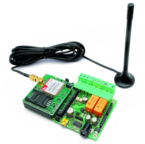
Universal GSM Remote Control module

TiDiGino_3.jpg

TiDiGino is a new open source Arduino-based (ATmega2560) GSM remote control module.  From open-electronics via dangerous prototypes

"The remote can be operated by commands sent by SMS, but you can also control it via the serial port (connected to USB converter).
Each command is followed by a response (via SMS) directly to the sender, but the answer may be disabled. In addition there is an alarm function, as the automatic sending of SMS or voice calls, based on conditions on each of the two inputs.
The circuit can also be used as a gate control, calling the SIM in the TiDiGino: the system recognize the calling number and if this number is stored the relay will switch on. In the DTMF mode, the remote control can be controlled by a multi-frequency telephone tone.
In addition, the circuit can operate as a thermostat, running an air conditioning system."

Read more…

I've had a lot of questions recently about the USA trip I'm planning, and thought I'd provide some additional details about what plane, FPV, AP, RTH, etc system I'll be using for the journey.

Basically, I'm planning on scratch building a twin engine airplane with a 6 -7 ft. wing span. It will fly at 60 - 80 MPH for as long as possible (hope to get an hour or more at that speed). I'll land it, replace the batteries, service the airplane, and take off again, repeating this until I reach the other side of the US.

I'll need a team of 4: a pilot, a driver (of the chase car we'll ride in), a navigator (works between pilot and driver to maintain proper proximity with the airplane), and an engineer (charges batteries, watches current airplane performance, etc.)

Planning on doing it in 2014. Why? I want lots of experience before attempting this, and, I need to save up some cash to pay for it all! Sponsors welcome!

Feel free to provide feedback!

Thanks!

Read more…

Reliable takeoffs

marcy1_46.jpg


This continues to move forward.  Decided attitude sensing is required for what we need.

After some complicated math problems, finally derived an empirical method for determining attitude from video.  It most definitely isn't accurate enough for our needs.  There's going to be a lot of horizontal drift.  The tilt of the camera has a big effect on it.

The takeoff is still problematic.  Attitude really needs to be level before it lifts off.  It's most definitely not passively stable.

PID tuning for attitude control with the altitude control nailed down.  It's most definitely not passively stable.


The great problem with Marcy 1 is devising a stabilized takeoff.  It needs to start tracking position at some point before it can actually track position.


The 1st algorithm was to apply fixed throttle that was known to go fast enough to control attitude but not take off.  Once the RPM was certain to be fast enough to return a valid position & attitude, apply cyclic to level the attitude without increasing throttle.  

This has been killing us, since attitude oscillates at low throttle.  For now, it just ramps up at the point in the oscillation when it's level enough & hopes there's enough control to keep it level. 


The moment it starts ramping up, it starts tracking position.  Since it can't move, the integrals build up.


Making it ignore position until reaching a minimum altitude has been tried.  The takeoff attitude is never level because the camera is never level, so it would fly away without active control.


 Resetting the integrals before reaching a minimum altitude, but having proportional feedback is yet to be tried.  Trying to stabilize the oscillation at low RPM, with derivatives is yet to be tried.


Loosening the steel wire to give it some horizontal range has shown whether or not feedback was going in the right direction.  Another idea is using fishing line instead of steel & tightening it if it gets out of control.

Marcy 1 does 4 autonomous flights without the tether. It's pretty bad. Throttle is a lot more unstable. Position tracking is erratic. The last crash might have been an unknown air current. Put a lot of work into making the takeoffs exactly level. Honestly thought that would never happen, but we got level takeoffs. Now, the XY camera movement seems to confuse it.

  Began by running the takeoff sequence up to the stabilized attitude stage to show machine vision could keep it level. Then switched to manual mode with cyclic at neutral to show how it doesn't naturally stay level. Then ran down the battery with the stabilized attitude on, to show the algorithm could keep it level for all battery voltages.

Perfectly level attitude is required for takeoff. Deglitching the video & getting such a slowly rotating blade level was a buster.

Reasonably pleased with new progress in leveling the aircraft on the test stand.  Maintaining a perfectly level aircraft during the takeoff is key to everything else.

Key to leveling the aircraft was using much higher gains than we used before.  A manual test showed the D gain was capable of an amazing job stabilizing the aircraft.

Also, application of the deglitching algorithm formerly used in sonar to the vision system greatly improved matters without causing a delay.  Finally, the trig had some more corner case tests.

Currently, the next flight test is programmed to feed position directly to cyclic, because vision isn't seen as accurate enough to give useful attitude information on a moving object.  All these changes still may get it to work with attitude hold.

Need to find more propellers 1st.  All suppliers are moving to China.  It takes several months to get anything from China. We've actually haven't gotten anything from the last 2 hobbyking orders.


More stable takeoff algorithm, deglitching, & direct position to cyclic feedback, but still no luck.  It's taking 1 propeller for every 4 test flights. 


We got the takeoffs very reliable.  It doesn't fly off the stand in a random direction unless the propeller breaks.  The only algorithm left is going back to the attitude feedback.

Read more…
3D Robotics

3689439326?profile=original

At CES today, Parrot announced the latest updates to its AR.Drone. The most interesting bits are higher resolution video and an onboard baro sensor that will allow it to fly higher than sonar range outside. The phone/tablet app also has a better FPV mode. 

Here's the full text of the release:

Parrot ‘AR.Drone 2.0’:

High-Definition Excitement!

At CES Las Vegas 2012, Parrot, a global leader in wireless devices for mobile phones, reveals the
AR.Drone 2.0, the new generation of its renowned high-tech quadricopter that can be controlled by Wi-Fi
using a smartphone or tablet.

With a new high-definition camera, video recording, flight data sharing, new piloting mode, increased stability
and brand-new look, the AR.Drone 2.0 offers an experience like no other!

A flying HD camera

While in flight, the Parrot AR.Drone 2.0's front camera transmits real-time what the quadricopter
sees onto the pilot’s device screen.

For the first time the AR.Drone 2.0 camera, with a 1280x720 resolution, shows a view from the
sky in high definition with smooth and unbelievable images.

The pilot enjoys an experience like never before, as if he was on board. For gaming purposes, this
camera also can recognize specific shapes and colors to show augmented-reality elements on the
smartphone's screen.

Record and share flying experiences

Thanks to the new AR.FreeFlight 2.0 piloting application, players can record their own HD
videos and watch them or share them with the AR.Drone community.

Additionally, with the "travelling" feature, the pilot can film HD video sequences like a
professional! Simply select the direction of travel (forward, back, sideways) and the duration, and
the AR.Drone 2.0 does the rest.


AR.FreeFlight 2.0, a new piloting and sharing platform

In addition to flying the AR.Drone, new application AR.FreeFlight 2.0 – available to download
for free from the AppStoreSM and AndroidTM Market – offers players a new interface and several
options.

. FreeFlight: Access to the piloting application.
The pilot can record flights, take HD videos or photos
and save them in the piloting device. All the flight data
(altitude, speed, duration and place) can be saved,
checked by the pilot and shared with the community.
. Guest Space: Access an overview of the AR.Drone
2.0, the best flight videos and practical information.
. Drone Update: Access the AR.Drone 2.0's free
software updates.
. AR.Drone Academy: Get geolocation data of the best flight zones, watch other pilots' videos
and access their shared flight data.
. AR.Games: Access applications/games available for the AR.Drone.
. Photos/Videos: Directly access your own videos and photos. Watch or upload to YouTube
for the community to enjoy.

‘Absolute Flight’, a revolutionary ultra-intuitive flight mode

After the AR.FreeFlight 2.0 pilot application has been loaded onto an iOS or AndroidTM
smartphone or tablet, the Parrot AR.Drone 2.0 connects to the device via Wi-Fi. After
connection, all the on-board instruments appear on screen with a cockpit view.

Press the take off button briefly and the four brushless motors turn on. The AR.Drone 2.0 takes
off.

Flying is very simple. With your thumbs placed on either side of the screen, a control button
automatically forms beneath:

. Press and hold the left button and the AR.Drone
2.0 follows the movement of the pilot's device: it
moves forward, backwards or sideways when you tilt
the tablet forward, towards you or to the left or
right.
. Slide your finger over the right button, and the
quadricopter rises, descends or rotates right or left.

Thanks to Parrot's patented new ‘Absolute Control’ mode, the player accesses an even more
intuitive piloting system.

With a 3D magnetometer, the AR.Drone 2.0 knows its precise orientation with respect to the
smartphone, which becomes the reference point. The pilot no longer needs to care about the
orientation of the AR.Drone 2.0's front camera, which will accurately track the smartphone's
motion and tilt.

Experienced players will select ‘Relative Flight’ mode, the conventional flight mode. This
disables Parrot AR.Drone 2.0's magnetometer. The pilot manages the quadricopter's orientation
with no assistance.


Surprising stability at any altitude

The heart of the AR.Drone 2.0 contains MEMS (microelectromechanical systems).
A 3-axis accelerometer, a 3-axis gyroscope, a 3-axis magnetometer and a pressure sensor
give the Parrot AR.Drone 2.0 surprising stability, complete with:

. 2 ultrasound sensors, which analyze flight altitude up to 6 meters.
New! A pressure sensor completes the device and provides great vertical
stability.
. 4 blades, specially designed for the AR.Drone 2.0, make it possible to carry
out smooth flights.
. A second camera, placed beneath the quadricopter and connected to the central inertial unit,
measures the craft's speed using an image comparison system.

2 hulls made for both types of flight

The Parrot AR.Drone 2.0 has 2 hulls with specially designed contours. Made of PA66 (a
material used in designing car bumpers), they are light, highly resistant and protect the
quadricopter.

For outdoor flight, the contoured hull, available in three colors
(orange/yellow; orange/green; orange/blue), reduces wind resistance and
preserves the AR.Drone 2.0's handling and stability.

When indoor, a second hull protects the blades
from any impact. The black-and-white cockpit,
underlined with a red stripe, reinforces the quadricopter's mysterious,
thrilling appearance.

Finally, light-emitting diodes (green in front, red in rear), positioned on the landing gear, help the
pilot track the orientation of the AR.Drone 2.0 for easier flying.

An Open Development Platform

In order to expand the use of the Parrot AR.Drone 2.0 and its compatibility with other
operating systems and to develop new flying games and applications, Parrot is providing
developers and members of the Apple® and AndroidTM communities with a software
development kit.

By logging in at https://projects.ardrone.org and accepting the terms of the license, developers can
access the source code used to fly the AR.Drone 2.0. A wiki and a tutorial also are available. A
forum is available to discuss new developments and share feedback with Parrot engineers.

***

The Parrot AR.Drone 2.0 runs on a rechargeable lithium-ion battery (included).

Parrot AR.Drone 2.0 will be available for purchase at selected retailers in Q2-2012 in the United States
for $299 MSRP

*

Read more…

Start of my laser-cut truss QuadCopter

Well, I decided to start seriously designing and building my quad-copter frame.  I recently build a CNC laser and can use that to cut all the parts I need for the frame.  I plan to use polycarbonate because it is strong, tough, and fairly light.  I've been exploring ultra light design principles.  The idea is that you can use very thin materials to make truss structures that may be quite flexible out of the truss plane but you add enough trusses in the out of plane direction to stiffen up the entire structure so that it is strong enough to resist bending moments in any direction.  I call this "box trussing".  It is very similar to a torsion box that is commonly used to make very strong, light weight work tables in wood working.

3689440371?profile=originalThe copter arms are truss structures with spacers that are also truss structures.  The arm sides are made from 0.04" thick polycarbonate and the spacers are made from 0.03" thick material.  The entire structure weighs just over 18.6 grams for one arm and will be more than strong and stiff enough to handle the forces generated during normal flight activities.  The following shows a side view with the hidden edges showing.

3689440462?profile=originalAll modes of shear and torsion are isolated with various truss members.  The polycarbonate is fairly stiff, but flexible in an out of plane bending mode, but is very strong in tension and decently strong in compression.  Using an X shape in the truss is very important because in a shear moment, one member will be under tension.  The proof will be in building the unit.  Also, one of the benefits of using polycarbonate is that it can be solvent welded with methylene-chloride which essentially makes the joints as strong as the plastic itself.

There is only a few dollars of poly carbonate in the frame so if I crash it, it's no big deal.  I can make another one in an hour or so.

Read more…